CN218474555U - Water tank assembly and cleaning robot with same - Google Patents
Water tank assembly and cleaning robot with same Download PDFInfo
- Publication number
- CN218474555U CN218474555U CN202222295582.3U CN202222295582U CN218474555U CN 218474555 U CN218474555 U CN 218474555U CN 202222295582 U CN202222295582 U CN 202222295582U CN 218474555 U CN218474555 U CN 218474555U
- Authority
- CN
- China
- Prior art keywords
- sewage
- tank
- water tank
- cleaning
- assembly
- Prior art date
- Legal status (The legal status is an assumption and is not a legal conclusion. Google has not performed a legal analysis and makes no representation as to the accuracy of the status listed.)
- Active
Links
- XLYOFNOQVPJJNP-UHFFFAOYSA-N water Substances O XLYOFNOQVPJJNP-UHFFFAOYSA-N 0.000 title claims abstract description 105
- 238000004140 cleaning Methods 0.000 title claims abstract description 67
- 239000010865 sewage Substances 0.000 claims abstract description 179
- 239000007921 spray Substances 0.000 claims abstract description 38
- 238000005086 pumping Methods 0.000 claims abstract description 7
- 238000001914 filtration Methods 0.000 claims description 9
- 238000005507 spraying Methods 0.000 claims description 8
- 238000010408 sweeping Methods 0.000 claims description 6
- 238000011010 flushing procedure Methods 0.000 claims description 2
- 238000005406 washing Methods 0.000 abstract description 18
- 238000012423 maintenance Methods 0.000 abstract description 3
- 239000007787 solid Substances 0.000 description 12
- 239000012535 impurity Substances 0.000 description 10
- 239000010813 municipal solid waste Substances 0.000 description 10
- 239000002351 wastewater Substances 0.000 description 9
- 230000000694 effects Effects 0.000 description 7
- 238000000034 method Methods 0.000 description 5
- VTYYLEPIZMXCLO-UHFFFAOYSA-L Calcium carbonate Chemical compound [Ca+2].[O-]C([O-])=O VTYYLEPIZMXCLO-UHFFFAOYSA-L 0.000 description 4
- 238000010521 absorption reaction Methods 0.000 description 4
- OSGAYBCDTDRGGQ-UHFFFAOYSA-L calcium sulfate Chemical compound [Ca+2].[O-]S([O-])(=O)=O OSGAYBCDTDRGGQ-UHFFFAOYSA-L 0.000 description 4
- 230000008569 process Effects 0.000 description 4
- 230000002349 favourable effect Effects 0.000 description 3
- 239000002699 waste material Substances 0.000 description 3
- 229910000019 calcium carbonate Inorganic materials 0.000 description 2
- 239000000428 dust Substances 0.000 description 2
- -1 hair Substances 0.000 description 2
- 230000003434 inspiratory effect Effects 0.000 description 2
- ZLNQQNXFFQJAID-UHFFFAOYSA-L magnesium carbonate Chemical compound [Mg+2].[O-]C([O-])=O ZLNQQNXFFQJAID-UHFFFAOYSA-L 0.000 description 2
- 229910000021 magnesium carbonate Inorganic materials 0.000 description 2
- 239000001095 magnesium carbonate Substances 0.000 description 2
- 238000004519 manufacturing process Methods 0.000 description 2
- 239000002910 solid waste Substances 0.000 description 2
- 238000003860 storage Methods 0.000 description 2
- 239000008399 tap water Substances 0.000 description 2
- 235000020679 tap water Nutrition 0.000 description 2
- 241000894006 Bacteria Species 0.000 description 1
- 230000009471 action Effects 0.000 description 1
- 239000000956 alloy Substances 0.000 description 1
- 229910045601 alloy Inorganic materials 0.000 description 1
- 230000009286 beneficial effect Effects 0.000 description 1
- 230000008021 deposition Effects 0.000 description 1
- 238000001035 drying Methods 0.000 description 1
- 230000006872 improvement Effects 0.000 description 1
- 238000009434 installation Methods 0.000 description 1
- 230000007774 longterm Effects 0.000 description 1
- 239000003595 mist Substances 0.000 description 1
- 230000004048 modification Effects 0.000 description 1
- 238000012986 modification Methods 0.000 description 1
- 230000002093 peripheral effect Effects 0.000 description 1
- 238000005201 scrubbing Methods 0.000 description 1
- 239000010802 sludge Substances 0.000 description 1
- 230000035943 smell Effects 0.000 description 1
Images



Landscapes
- Sewage (AREA)
Abstract
The application provides a water tank set spare and have its cleaning robot. The application relates to a water tank assembly, comprising: a clear water tank; a sewage tank; the self-cleaning device comprises a cleaning pipeline, a water pump and a spray head, wherein the water pump is arranged on the cleaning pipeline, one end of the cleaning pipeline is communicated with the clean water tank, the other end of the cleaning pipeline is communicated with the spray head, the spray head is arranged in the sewage tank, and the water pump is used for pumping clean water in the clean water tank to the spray head and washing the inner side wall of the sewage tank by the spray head. The application provides a water tank set spare, shower head can spatter on the sewage case inside wall and spill the dirt of leaving behind and in time clear up, can enough reduce the siltation of dirt on the lateral wall, also need not also that the operation is accomplished the back manual work and clean, consequently, also can improve the sanitary situation of sewage incasement when reducing the maintenance cost. The application also correspondingly provides a cleaning robot.
Description
Technical Field
The application belongs to the technical field of it is clean, more specifically say, relate to a water tank set spare and have its cleaning robot.
Background
The cleaning robot generally comprises a clean water tank, a sewage tank and a ground washing assembly, wherein the ground washing assembly comprises a water absorption rake, and the water absorption rake is communicated with the sewage tank through a sewage pipeline. When cleaning, the fan in the cleaning robot generates negative pressure in the sewage tank so that the sewage tank generates suction force on the sewage pipeline, and then the water sucking rake sucks up and conveys the sewage on the ground into the sewage tank. However, during operation, the sewage is easily splashed in the process of flowing into the sewage tank after being sucked by negative pressure, and impurities such as hair, dust and the like are often mixed in the sewage, so that the impurities are splashed onto the side wall of the sewage tank after the sewage flows into the sewage tank, and sticky dirt which is difficult to clean is formed. The dirt generally needs manual cleaning, the manual cleaning time is high in cost, and if the dirt is not cleaned in time, bacteria are easily bred in the dirt in the sewage tank, so that the sanitation condition in the sewage tank is poor.
SUMMERY OF THE UTILITY MODEL
An object of the embodiment of the application is to provide a water tank set spare and have its cleaning robot to solve the technical problem that the dirt in the sewage case that exists among the prior art is difficult to in time clear up.
In order to achieve the purpose, the technical scheme adopted by the application is as follows: there is provided a water tank assembly comprising:
a clear water tank;
a sewage tank;
the self-cleaning device comprises a cleaning pipeline, a water pump and a spray head, wherein the water pump is arranged on the cleaning pipeline, one end of the cleaning pipeline is communicated with the clean water tank, the other end of the cleaning pipeline is communicated with the spray head, the spray head is arranged in the sewage tank, and the water pump is used for pumping clean water in the clean water tank to the spray head and washing the inner side wall of the sewage tank by the spray head.
Optionally, the shower head frame is arranged at the top of the inner cavity of the sewage tank.
Optionally, an extension frame is arranged on the top of the inner side wall of the sewage tank, the extension frame extends from the side wall of the sewage tank to the middle of the sewage tank, and the spray header is arranged at the tail end of the extension frame.
Optionally, the showerhead is a rotary showerhead.
Optionally, the self-cleaning device further comprises a filter device disposed on the cleaning line.
Optionally, a splash guard is disposed at a sewage inlet of the sewage tank, an end of the sewage pipeline extends into the splash guard through the sewage inlet, and the splash guard is used for preventing sewage flowing into the sewage tank from splashing on an inner side wall of the sewage tank.
Optionally, the splash guard is open at the bottom, and in the assembled state, the opening of the splash guard faces the bottom of the waste water tank.
Optionally, the sewage case sewage entrance still is provided with the filter mantle, the splashproof lid is established the filter mantle, sewage pipe's tip by sewage entrance extends into in the filter mantle.
Optionally, a clamping frame is arranged on the inner side wall of the sewage tank, and the splash guard and/or the filter cover are/is mounted on the clamping frame.
Correspondingly, this application still provides a cleaning robot, including foretell water tank set spare, still including washing ground subassembly and sweeping the floor the subassembly, wherein, wash ground subassembly pass through the sewage pipeline with the sewage entry of sewage case is linked together.
The application provides a water tank set spare has following beneficial effect at least:
through set up clean pipeline and water pump between sewage case closes the clear water tank, and simultaneously, set up the shower head in the sewage incasement, the water pump can be used for with the clear water pump sending in the clear water case to the shower head and spray to the inside wall of sewage case by the shower head, so, in clean process, the shower head can splash on the sewage incasement wall and spill the dirt of leaving over and in time clear up, can enough reduce the siltation of dirt on the lateral wall, also need not to accomplish the back manual work at the operation and clean, therefore, also can improve the sanitary situation of sewage incasement when reducing the maintenance cost.
Drawings
In order to more clearly illustrate the technical solutions in the embodiments of the present application, the drawings needed to be used in the embodiments or the prior art descriptions will be briefly described below, and it is obvious that the drawings in the following description are only some embodiments of the present application, and it is obvious for those skilled in the art to obtain other drawings based on these drawings without inventive exercise.
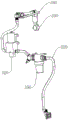
FIG. 1 is a front view of a water tank assembly according to some embodiments of the present application;
FIG. 2 is a perspective view of a water tank assembly according to some embodiments of the present application;
FIG. 3 is a perspective view of a self-cleaning apparatus according to some embodiments of the present application;
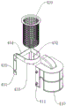
FIG. 4 is an assembly view of a splash guard and filter shroud according to some embodiments of the present application;
fig. 5 is an exploded view of a clip frame, splash guard, and filter cage according to some embodiments of the present application.
Wherein, in the figures, the respective reference numerals:
100. a clear water tank;
200. a sewage tank;
300. a self-cleaning device;
310. cleaning a pipeline; 320. a water pump; 330. a shower head; 340. an extension frame; 350. a filtration device;
410. a splash guard; 411. a clamping block;
420. a filter housing;
430. a clamping frame; 431. a first clamp arm; 432. a second clamp arm; 433. a first connecting arm; 434. a second connecting arm; 435. a card slot;
500. a sewage pipeline.
Detailed Description
In order to make the technical problems, technical solutions and advantageous effects to be solved by the present application clearer, the present application is further described in detail below with reference to the accompanying drawings and embodiments. It should be understood that the specific embodiments described herein are merely illustrative of and not restrictive on the broad application.
It will be understood that when an element is referred to as being "secured to" or "disposed on" another element, it can be directly on the other element or be indirectly on the other element. When an element is referred to as being "connected to" another element, it can be directly connected to the other element or be indirectly connected to the other element.
It will be understood that the terms "length," "width," "upper," "lower," "front," "rear," "left," "right," "vertical," "horizontal," "top," "bottom," "inner," "outer," and the like, as used herein, refer to an orientation or positional relationship indicated in the drawings that is solely for the purpose of facilitating the description and simplifying the description, and do not indicate or imply that the device or element being referred to must have a particular orientation, be constructed and operated in a particular orientation, and thus should not be considered as limiting the present application.
Furthermore, the terms "first", "second" and "first" are used for descriptive purposes only and are not to be construed as indicating or implying relative importance or implicitly indicating the number of technical features indicated. Thus, a feature defined as "first" or "second" may explicitly or implicitly include one or more of that feature. In the description of the present application, "a plurality" means two or more unless specifically limited otherwise.
Referring to fig. 1 to 5 together, a water tank assembly according to an embodiment of the present application will now be described. The water tank assembly comprises:
a clear water tank 100;
a sewage tank 200;
the self-cleaning device 300 comprises a cleaning pipeline 310, a water pump 320 and a spray header 330, wherein the spray header 330 is arranged in the sewage tank 200, one end of the cleaning pipeline 310 is communicated with the clean water tank 100, the other end of the cleaning pipeline 310 is communicated with the spray header 330, the water pump 320 is arranged on the cleaning pipeline 310, and the water pump 320 is used for pumping clean water in the clean water tank 100 to the spray header 330 and flushing the inner side wall of the sewage tank 200 by the spray header 330.
Generally, a washing robot is provided with a floor washing assembly and a water absorption rake, the floor washing assembly is used for spraying water to a floor and wiping the floor for cleaning, and the water absorption rake is used for absorbing sewage generated by wiping and cleaning the floor, so that the work flow of floor cleaning is completed.
In addition, referring to fig. 1 and 2, a clean water tank 100 and a sewage tank 200 are provided on the washing robot, the clean water tank 100 is used for storing clean water, and the clean water tank 100 is communicated with the floor washing assembly in the washing robot through a clean water pipeline for pumping clean water to the floor washing assembly for use by the floor washing assembly to clean the floor.
The sewage tank 200 is used for storing sewage, and the sewage tank 200 is communicated with the suction rake through a sewage pipeline 500, specifically, the outlet of the sewage pipeline 500 in the sewage tank 200 of the sewage pipeline 500 is positioned at the top of the side wall of the sewage tank 200, so as to store the sewage sucked by the suction rake therein; further, a vacuum pumping device is arranged in the sewage tank 200, and is used for vacuumizing the inside of the sewage tank 200 to generate negative pressure, and meanwhile, as the sewage pipeline 500 is communicated with the sewage tank 200, when negative pressure is generated in the sewage tank 200, negative pressure is also generated in the sewage pipeline 500, and the negative pressure in the sewage pipeline 500 acts on the water-absorbing rakes to pump and pump sewage on the floor contacted by the water-absorbing rakes into the sewage tank 200, so that the drying of the floor and the storage of the sewage are realized.
Specifically, in the cleaning robot, since a large negative pressure exists in the sewage tank 200 during cleaning, when sewage flows out from the outlet of the sewage pipe 500 at the top of the sidewall of the sewage tank 200 into the sewage tank 200, the flow rate of the sewage is fast due to the negative pressure, and the water level in the sewage tank 200 is very low, generally 0, at the beginning of cleaning, so that when sewage flows into the sewage tank 200 from the outlet of the sewage pipe 500, the sewage is very easily splashed onto the sidewall of the sewage tank 200 due to the very low water level in the sewage tank 200. Further, since various impurities, such as hair, sludge, dust, etc., are often mixed in the sewage, and such impurities are generally sticky, when the impurities are splashed onto the side wall of the sewage tank 200, the impurities are adhered and adsorbed on the side wall of the sewage tank 200 to form dirt, and over time, the dirt is gradually condensed and smells along with the increase of the dirt and the repeated water intake and drainage of the sewage tank 200, resulting in a great difficulty in subsequent cleaning.
For this reason, in order to clean the dirt on the inner side wall of the sewage tank 200 in time, the sewage tank 200 and the clean water tank 100 are set as follows:
referring to fig. 1 and 2, in particular, a cleaning pipeline 310 is communicated between the clean water tank 100 and the sewage tank 200, a shower head 330 communicated with an outlet of the cleaning pipeline 310 is disposed in the sewage tank 200, and further, a water pump 320 is disposed on the cleaning pipeline 310, and the water pump 320 is used for pumping the clean water in the clean water tank 100 to the shower head 330 and spraying the clean water to the inner side wall of the sewage tank 200 through the shower head 330.
So, in the process that sewage flows into the sewage tank 200, the shower head 330 can continuously spray high-pressure clean water to the inside wall of the sewage tank 200, thereby timely removing impurities splashed to the inside wall of the sewage tank 200, wherein the removed impurities flow to the bottom of the sewage tank 200 along the inner side wall of the sewage tank 200 along with water flow, and the sewage in the sewage tank 200 is intensively discharged after the operation of the cleaning robot is completed.
Further, the shower head 330 is used for spraying high-pressure mist-like clean water to the fixed direction of the inner side wall of the sewage tank 200. Specifically, the showerhead 330 may have the following several arrangements. In some arrangements, the showerhead 330 may be a single showerhead 330 disposed on an inner sidewall of the waste tank 200; or, in other arrangement modes, two or more spray headers 330 may be arranged, each spray header 330 is arranged at a certain distance, and each spray header 330 sprays high-pressure atomized clear water in a fixed direction in the sewage tank 200; or, the spray header 330 may also be set to be a hollow pipe, the hollow pipe is disposed around each inner sidewall of the sewage tank 200, and a plurality of water outlets are spaced at one side of the hollow pipe facing the inner sidewall of the sewage tank 200, so that when the water pump 320 is started, the spray header 330 can spray high-pressure mist clean water to each inner sidewall of the sewage tank 200 at the same time, thereby improving the cleaning efficiency.
In conclusion, the water tank assembly of the application has the advantages that the cleaning robot can clean the inner side wall of the sewage tank 200 in time by splashing and splashing the left-over dirt through the spray head 330 in the cleaning process, the deposition of the dirt on the side wall can be reduced, and the cleaning is not needed to be performed manually after the operation is completed, so that the maintenance cost is reduced, and meanwhile, the sanitation condition in the sewage tank 200 can be improved.
Further, referring to fig. 2, in some embodiments of the present application, a shower head 330 is mounted to the top of the interior volume of the waste tank 200. By such arrangement, the maximum spraying height of the spray header 330 is high, so that the cleaning area of the inner side wall of the sewage tank 200 can be increased as much as possible, the generation of dead angles is reduced, and the sanitary condition in the sewage tank 200 is improved.
It can be understood that, referring to fig. 2 and 3, in some embodiments of the present application, an extension frame 340 is disposed on the top of the inner sidewall of the waste water tank 200, the extension frame 340 is disposed to extend from the sidewall of the waste water tank 200 to the middle of the waste water tank 200, specifically, the extension frame may be made of alloy or rigid plastic, the shower head 330 is disposed at the end of the extension frame 340, and an extension pipe is connected between the shower head 330 and the cleaning pipe 310. Through so setting up, can increase shower head 330 to the clean scope of spraying of sewage case 200 inside wall to improve clean efficiency, and, set up low cost, it is also comparatively convenient to maintain.
Further, referring to fig. 2, in some embodiments of the present application, the showerhead 330 is a rotary spray head. The rotary nozzle is driven to rotate by the high-pressure water flow pumped by the water pump 320, so that the rotary nozzle can rotate at a constant speed at a certain peripheral speed. So, rotatory nozzle is at the rotation in-process, and when the vaporific clear water of high pressure sprayed the inside wall of sewage case 200, the clear water is swept in the inside wall of sewage case 200 at certain speed under inertial effect to play the effect of scrubbing, compare in the directional spraying to the inside wall of sewage case 200 on, so, can further improve clean effect.
Further, referring to fig. 1 and 3, in some embodiments of the present application, the self-cleaning device 300 further includes a filtering device 350, and the filtering device 350 is disposed on the cleaning line 310.
It can be understood that, since the clean water is generally tap water, calcium carbonate, magnesium carbonate, calcium sulfate, etc. naturally contained in the tap water may block the rotary nozzle during long-term use, thereby causing a small spraying flow rate of the rotary nozzle. Therefore, the cleaning pipeline 310 is provided with the filtering device 350, and the filtering device 350 is used for filtering impurities such as calcium carbonate, magnesium carbonate and calcium sulfate in the filtered water so as to ensure that the rotary spray head can spray clear water efficiently and smoothly.
Specifically, the filtering device 350 may be disposed between the inlet of the cleaning pipeline 310 and the water pump 320, or between the water pump 320 and the spin head.
It will be appreciated that, referring to fig. 2, 4 and 5, in some embodiments of the present application, a splash guard 410 is provided at a sewage inlet of the sewage tank 200, an end of the sewage pipe 500 extends into the splash guard 410 from the sewage inlet, and the splash guard 410 serves to prevent sewage flowing into the sewage tank 200 from splashing on an inner sidewall of the sewage tank 200.
So, set up splash guard 410 through the sewage entrance at sewage case 200, make by the inspiratory sewage of negative pressure when getting into sewage case 200 inside by sewage pipe way 500, can play the water conservancy diversion and converge the effect to sewage, sewage converges to inside sewage case 200 with certain fixed angle under the water conservancy diversion effect of splash guard 410, thereby reduce the production that spatters, and then reduce the splash of impurity, also reduce the production of stubborn dirt on the sewage case 200 inside wall, therefore be favorable to keeping the cleanness of sewage case 200 inside wall, reduce the inside clean degree of difficulty of sewage case 200.
Specifically, the splash guard 410 may be a semi-enclosed baffle in the shape of an arc; or, the cover body can also be semi-closed and has an opening at one end. For example, referring to fig. 4 to 5, the splash guard 410 is provided with a bottom opening, and in an assembled state, the opening of the splash guard 410 faces the bottom of the wastewater tank 200. Due to the arrangement of the splash guard 410, sewage can be converged to the sewage tank 200 along the vertical direction under the flow guiding effect of the splash guard 410, so that the generation of splash can be reduced, the splashing phenomenon of the sewage can be relieved, and the generation of dirt on the inner side wall of the sewage tank 200 can be reduced.
In addition, when the suction rake sucks sewage on the floor, the floor is inevitably left with large solid garbage, such as paper scraps, due to incomplete cleaning, the size of the solid garbage is smaller than that of a sewage suction port of the suction rake, and the density of the solid garbage is smaller than that of the sewage, so that the solid garbage floats on the water surface in the sewage tank 200 after the solid garbage is sucked into the sewage tank 200. Since the vacuum suction inlet is arranged in the sewage tank 200, floating solid garbage is easily sucked into the fan under the action of negative pressure, so that the air duct of the fan is blocked, and even the fan is overheated and fails.
To solve this problem and reduce the solid waste from entering the inside of the waste water tank 200, referring to fig. 4 to 5, in some embodiments of the present application, a filter cover 420 is further provided at the waste water inlet of the waste water tank 200, a splash cover 410 is covered on the filter cover 420, and the end of the waste pipe 500 extends into the filter cover 420 from the waste water inlet. So set up, filter cover 420 can intercept the solid rubbish that absorbs water and take off the inspiratory and temporary storage in filter cover 420, reduces the volume of leaving over of solid in the sewage to be favorable to guaranteeing the fan normal operating, the washing of the sewage case 200 of also being convenient for is maintained.
Specifically, the filter casing 420 has a cylindrical shape with an open end, and a flange for engagement is provided at the open end. The manner in which filter cage 420 is assembled will be described in more detail below.
Referring to fig. 4 to 5, in some embodiments of the present invention, in order to facilitate the removal and installation of the filter cup 420 and the splash guard 410, a clip frame 430 is fixedly provided on an inner sidewall of the sump tank 200, and the splash guard 410 and/or the filter cup 420 are mounted on the clip frame 430.
Specifically, the clip frame 430 includes a first clip arm 431 and a second clip arm 432, and a first connection arm 433 in a half-loop assembly is connected between the first clip arm 431 and the second clip arm 432; meanwhile, a second connecting arm 434 is connected between the first catching arm 431 and the second catching arm 432, and the second connecting arm 434 is used for closing the annular opening of the first connecting arm 433. The first connecting arm 433 and the second connecting arm 434 together enclose an opening through which the filter cover 420 is inserted, the filter cover 420 is inserted into the opening, and an edge of one end of the filter cover is erected on the first connecting arm 433 and the second connecting arm 434. So, filter 420's convenient assembling is swift, when needs are cleared up the solid refuse who leaves it wherein, only need take it out can.
Meanwhile, in order to facilitate the disassembly and assembly of the splash guard 410, the following arrangement is made for the first catching arm 431 and the second catching arm 432. Specifically, the first clip arm 431 and the second clip arm 432 are symmetrically provided with the clip groove 435, and preferably, the clip groove 435 is inclined towards the bottom of the clip frame 430; correspondingly, the two vertical sides of the splash guard 410 are symmetrically provided with fixture blocks 411, and the fixture blocks 411 are used for being inserted into the fixture grooves 435 on the first fixture arm 431 and the second fixture arm 432. Thus, when the splash guard 410 is assembled, only the clamping blocks 411 on the two sides of the splash guard need to be inserted into the clamping grooves 435 on the clamping frames 430, so that the operation is simple and rapid, and the disassembly is also convenient.
In addition, correspondingly, the application also provides a cleaning robot, which comprises the water tank assembly, a ground washing assembly and a floor sweeping assembly, wherein the ground washing assembly is provided with a water sucking scratcher, and a sewage pipeline 500 is communicated with the water sucking scratcher and a sewage inlet of the sewage tank 200.
It will be appreciated that the sweeping assembly is used to sweep solid waste from a floor. Through setting up the subassembly of sweeping the floor, before washing the ground subassembly and wasing, sweep the clearance through the subassembly of sweeping the floor with solid rubbish on the floor earlier and finish for when absorbing water and taking off the sewage on absorbing the floor in the subassembly of washing the ground, solid rubbish on the floor has been already cleared up and finishes, therefore can prevent that solid rubbish from being inhaled sewage pipeline 500 and leading to sewage pipeline 500 to block up, thereby be favorable to improving and wash clean efficiency.
So, the cleaning robot of this application, it is higher to wash ground clean efficiency to, sewage case 200 can realize self-cleaning, need not artifical too much intervention in the use and can keep sewage case 200 clean, and it is convenient to maintain.
The above description is only exemplary of the present application and should not be taken as limiting the present application, as any modification, equivalent replacement, or improvement made within the spirit and principle of the present application should be included in the protection scope of the present application.
Claims (10)
1. A water tank assembly, comprising:
a clear water tank;
a sewage tank;
the self-cleaning device comprises a cleaning pipeline, a water pump and a spray header, wherein the water pump is arranged on the cleaning pipeline, one end of the cleaning pipeline is communicated with the clean water tank, the other end of the cleaning pipeline is communicated with the spray header, the spray header is arranged in the sewage tank, and the water pump is used for pumping clean water in the clean water tank to the spray header and flushing the inner side wall of the sewage tank by the spray header.
2. The water tank assembly of claim 1, wherein: the spraying head frame is arranged at the top of the inner cavity of the sewage tank.
3. The water tank assembly of claim 2, wherein: the top of the inner side wall of the sewage tank is provided with an extension frame, the extension frame extends from the side wall of the sewage tank to the middle of the sewage tank, and the spray header is arranged at the tail end of the extension frame.
4. A cistern assembly as claimed in any one of claims 1 to 3, wherein: the spray header is a rotary spray head.
5. The water tank assembly of claim 1, wherein: the self-cleaning device further comprises a filtering device, and the filtering device is arranged on the cleaning pipeline.
6. The water tank assembly of claim 1, wherein: sewage case's sewage entrance is provided with the splash guard, sewage pipeline's tip by sewage entrance extends into in the splash guard, the splash guard is used for preventing to flow into sewage case's sewage spatters spill in on the inside wall of sewage case.
7. The water tank assembly of claim 6, wherein: the splash guard is the bottom opening setting, under the assembled state, the opening orientation of splash guard the bottom of sewage case.
8. A cistern assembly as claimed in any one of claims 6 to 7, wherein: the sewage case sewage entrance still is provided with the filter mantle, the splashproof shroud is established the filter mantle, sewage pipeline's tip by sewage entry extends into in the filter mantle.
9. The water tank assembly of claim 8, wherein: the inside wall of sewage case is provided with the card frame, the splashproof cover and/or the filter mantle install in the card frame.
10. A cleaning robot, comprising the water tank assembly of any one of claims 1 to 9, and further comprising a floor cleaning assembly and a floor sweeping assembly, wherein the floor cleaning assembly is communicated with a sewage inlet of the sewage tank through a sewage pipeline.
Priority Applications (1)
| Application Number | Priority Date | Filing Date | Title |
|---|---|---|---|
| CN202222295582.3U CN218474555U (en) | 2022-08-29 | 2022-08-29 | Water tank assembly and cleaning robot with same |
Applications Claiming Priority (1)
| Application Number | Priority Date | Filing Date | Title |
|---|---|---|---|
| CN202222295582.3U CN218474555U (en) | 2022-08-29 | 2022-08-29 | Water tank assembly and cleaning robot with same |
Publications (1)
| Publication Number | Publication Date |
|---|---|
| CN218474555U true CN218474555U (en) | 2023-02-14 |
Family
ID=85166694
Family Applications (1)
| Application Number | Title | Priority Date | Filing Date |
|---|---|---|---|
| CN202222295582.3U Active CN218474555U (en) | 2022-08-29 | 2022-08-29 | Water tank assembly and cleaning robot with same |
Country Status (1)
| Country | Link |
|---|---|
| CN (1) | CN218474555U (en) |
Cited By (2)
| Publication number | Priority date | Publication date | Assignee | Title |
|---|---|---|---|---|
| CN117565822A (en) * | 2023-12-25 | 2024-02-20 | 重庆达航工业有限公司 | A self-cleaning device for the sewage tank of an aircraft sewage truck |
| WO2025200589A1 (en) * | 2024-03-25 | 2025-10-02 | 广东德尔玛健康科技有限公司 | Cleaning method and apparatus for recovery component, and cleaning system and medium |
-
2022
- 2022-08-29 CN CN202222295582.3U patent/CN218474555U/en active Active
Cited By (2)
| Publication number | Priority date | Publication date | Assignee | Title |
|---|---|---|---|---|
| CN117565822A (en) * | 2023-12-25 | 2024-02-20 | 重庆达航工业有限公司 | A self-cleaning device for the sewage tank of an aircraft sewage truck |
| WO2025200589A1 (en) * | 2024-03-25 | 2025-10-02 | 广东德尔玛健康科技有限公司 | Cleaning method and apparatus for recovery component, and cleaning system and medium |
Similar Documents
| Publication | Publication Date | Title |
|---|---|---|
| US8215322B2 (en) | Dishwasher with soil removal | |
| CN100381090C (en) | Complex type cleaner | |
| CN209847089U (en) | Cleaning robot | |
| CN112842177A (en) | Cleaning machines people water tank and cleaning machines people | |
| CN215959695U (en) | Base station | |
| KR20100130293A (en) | Vacuum cleaner | |
| CN100413446C (en) | Complex type cleaner | |
| CN101072619A (en) | Wet type air cleaner | |
| CN215502760U (en) | Cleaning machine system with base station | |
| CN217525002U (en) | Cleaning device of floor cleaning machine roller brush | |
| US10368712B2 (en) | Surface maintenance vehicle with self-cleaning reservoir that captures hose runoff | |
| CN111067412A (en) | A water-absorbing brush with a water-vapor separation structure | |
| CN212914993U (en) | A pipeline processing waste gas dust removal device | |
| CN112932355B (en) | Cleaning and recycling system with flow guide device and cleaning robot | |
| CN209362093U (en) | A kind of wet scrubber tower for waste gas purification | |
| CN218792089U (en) | Surface cleaning device convenient to clearance | |
| CN217039960U (en) | Floor brush | |
| CN212307699U (en) | Water absorption brush with water-gas separation structure | |
| CN216135807U (en) | Cleaning machines people water tank and cleaning machines people | |
| CN211202038U (en) | Colliery is dust collector in pit | |
| CN212307698U (en) | Water-absorbing brush head | |
| KR20020075523A (en) | Wet circular cleaner | |
| CN218932981U (en) | Self-cleaning dust fall washing and sweeping vehicle of fan | |
| CN222817132U (en) | Water curtain cyclone paint spraying cabinet | |
| CN114652215A (en) | Cleaning machine system with base station |
Legal Events
| Date | Code | Title | Description |
|---|---|---|---|
| GR01 | Patent grant | ||
| GR01 | Patent grant | ||
| TR01 | Transfer of patent right |
Effective date of registration: 20231019 Address after: 518000 Wanke Yuncheng Phase 4, Dashi 1st Road, Xili Community, Xishan District, Shenzhen City, Guangdong Province (Centralized Commercial Project) A08 (12-08) Patentee after: Kandra (Shenzhen) Intelligent Technology Co.,Ltd. Address before: 518000 room 2701, block B, building 7, Shenzhen International Innovation Valley, Dashi 1st Road, Xili community, Xili street, Nanshan District, Shenzhen, Guangdong Patentee before: CANDELA (SHENZHEN) TECHNOLOGY INNOVATION Co.,Ltd. |
|
| TR01 | Transfer of patent right |