Patents
Search within the title, abstract, claims, or full patent document: You can restrict your search to a specific field using field names.
Use TI= to search in the title, AB= for the abstract, CL= for the claims, or TAC= for all three. For example, TI=(safety belt).
Search by Cooperative Patent Classifications (CPCs): These are commonly used to represent ideas in place of keywords, and can also be entered in a search term box. If you're searching forseat belts, you could also search for B60R22/00 to retrieve documents that mention safety belts or body harnesses. CPC=B60R22 will match documents with exactly this CPC, CPC=B60R22/low matches documents with this CPC or a child classification of this CPC.
Learn MoreKeywords and boolean syntax (USPTO or EPO format): seat belt searches these two words, or their plurals and close synonyms. "seat belt" searches this exact phrase, in order. -seat -belt searches for documents not containing either word.
For searches using boolean logic, the default operator is AND with left associativity. Note: this means safety OR seat belt is searched as (safety OR seat) AND belt. Each word automatically includes plurals and close synonyms. Adjacent words that are implicitly ANDed together, such as (safety belt), are treated as a phrase when generating synonyms.
Learn MoreChemistry searches match terms (trade names, IUPAC names, etc. extracted from the entire document, and processed from .MOL files.)
Substructure (use SSS=) and similarity (use ~) searches are limited to one per search at the top-level AND condition. Exact searches can be used multiple times throughout the search query.
Searching by SMILES or InChi key requires no special syntax. To search by SMARTS, use SMARTS=.
To search for multiple molecules, select "Batch" in the "Type" menu. Enter multiple molecules separated by whitespace or by comma.
Learn MoreSearch specific patents by importing a CSV or list of patent publication or application numbers.
Dust removal environmental protection equipment
CN218459054U
China
- Info
- Legal events
- Similar documents
- Priority and Related Applications
- External links
- Espacenet
- Global Dossier
- Discuss
Description
translated from Chinese
技术领域technical field
本实用新型涉及环保清洁设备技术领域,尤其涉及一种除尘环保设备。The utility model relates to the technical field of environmental cleaning equipment, in particular to a dust removal environmental protection equipment.
背景技术Background technique
在工业生产或建筑施工时都会产生较多的粉尘和灰尘,粉尘和灰尘的弥散对环境的影响较大,也不利于操作人员的身体健康,不利于环保建设的发展,因此需要使用除尘设备进行除尘抑尘,以保证生产施工环境的清洁。A lot of dust and dust will be generated during industrial production or construction. The dispersion of dust and dust will have a great impact on the environment, and it is not conducive to the health of operators and the development of environmental protection construction. Therefore, it is necessary to use dust removal equipment. Dust removal and dust suppression to ensure the cleanliness of the production and construction environment.
现有的除尘装置使用布袋式除尘或滤网进行除尘,需要对除尘布袋或滤网进行频繁更换,增加了使用成本,也不便于长时间的除尘工作,不便于对吸收的粉尘进行降尘回收处理,使用效果一般。The existing dust removal device uses bag type dust removal or filter screen for dust removal, which requires frequent replacement of dust removal bag or filter screen, which increases the cost of use, and is not convenient for long-term dust removal work, and it is not convenient for dust reduction and recycling of absorbed dust , the effect is general.
实用新型内容Utility model content
本实用新型的目的是为了解决现有技术中存在需要对除尘布袋或滤网进行频繁更换,增加了使用成本,也不便于长时间的除尘工作,不便于对吸收的粉尘进行降尘回收处理,使用效果一般的缺点,而提出的一种除尘环保设备。The purpose of this utility model is to solve the problem of frequent replacement of dust bags or filter screens in the prior art, which increases the cost of use, is not convenient for long-term dust removal work, and is not convenient for dust reduction and recycling of absorbed dust. Due to the general shortcomings of the effect, a kind of dust removal and environmental protection equipment is proposed.
为了实现上述目的,本实用新型采用了如下技术方案:In order to achieve the above object, the utility model adopts the following technical solutions:
一种除尘环保设备,包括倾斜设置的过滤箱和进气管,所述过滤箱顶壁上设有排气口,所述进气管贯通插设在过滤箱较高一侧的侧壁上,所述进气管内转动设有涡轮风扇,涡轮风扇主轴向一侧延伸并连接在驱动电机的输出端上,驱动电机通过电机支架水平安装在过滤箱上方。A kind of dust removal and environmental protection equipment, comprising a filter box and an air intake pipe arranged obliquely, an exhaust port is arranged on the top wall of the filter box, and the air intake pipe is inserted through the side wall on the higher side of the filter box. A turbofan is rotated in the air inlet pipe, the main shaft of the turbofan extends to one side and is connected to the output end of the drive motor, and the drive motor is horizontally installed above the filter box through a motor bracket.
所述过滤箱下方设有循环水箱,循环水箱一侧设有净化水箱,净化水箱与循环水箱之间设有滤网,净化水箱内设有增压水泵,增压水泵的输出端上贯通连接有送水管,送水管向上延伸贯通进气管的侧壁设有多个雾化喷头。A circulating water tank is provided below the filter box, a purified water tank is provided on one side of the circulating water tank, a filter screen is provided between the purified water tank and the circulating water tank, a booster pump is provided in the purified water tank, and the output end of the booster pump is connected through a The water delivery pipe extends upwards and runs through the side wall of the intake pipe, and is provided with a plurality of atomizing nozzles.
所述过滤箱内腔下部平行设有除尘滤板,循环水箱远离净化水箱的一侧设有收集箱,所述收集箱上端贯通过滤箱与除尘滤板输出端相连接。The lower part of the inner cavity of the filter box is provided with a dust removal filter plate in parallel, and the side of the circulating water tank away from the purified water tank is provided with a collection box, and the upper end of the collection box is connected to the output end of the dust removal filter plate through the filter box.
所述除尘滤板前侧向前延伸贯穿过滤箱的侧壁并连接有密封板,且密封板靠近过滤箱的一侧设有相对应的密封圈,所述密封板前壁上还设有多个握把。The front side of the dust removal filter plate extends forward through the side wall of the filter box and is connected with a sealing plate, and the side of the sealing plate close to the filter box is provided with a corresponding sealing ring, and the front wall of the sealing plate is also provided with a plurality of grip.
优选的,所述过滤箱内腔上部转动设有与除尘滤板相对应的传送带,传送带外侧设有与除尘滤板相匹配的刷丝,传送带内转动设有多个转动辊,其中一个转动辊与驱动电机之间连接有传动组件。Preferably, the upper part of the inner chamber of the filter box is rotated to be provided with a conveyor belt corresponding to the dust removal filter plate, brush filaments matching the dust removal filter plate are provided on the outside of the conveyor belt, and a plurality of rotating rollers are installed in the conveyor belt, one of which is A transmission assembly is connected with the drive motor.
更优选的,所述传动组件包括第一带轮和第二带轮,其中第一带轮固定套设在转动辊的转动轴上,第一带轮和第二带轮之间连接有同步带,所述第二带轮转动安装在电机支架上并同轴连接有第一锥齿轮,第一锥齿轮啮合有第二锥齿轮,第二锥齿轮固定套设在驱动电机的输出端上。More preferably, the transmission assembly includes a first pulley and a second pulley, wherein the first pulley is fixedly sleeved on the rotating shaft of the rotating roller, and a timing belt is connected between the first pulley and the second pulley , the second pulley is rotatably installed on the motor bracket and coaxially connected with the first bevel gear, the first bevel gear meshes with the second bevel gear, and the second bevel gear is fixedly sleeved on the output end of the drive motor.
更优选的,所述过滤箱内腔中靠近除尘滤板输出端的一侧设有多个与刷丝相对应的清洁齿。More preferably, a plurality of cleaning teeth corresponding to the brush filaments are provided on the side near the output end of the dust removal filter plate in the inner chamber of the filter box.
优选的,所述过滤箱前壁上转动设有多个与密封板相匹配的锁紧块。Preferably, a plurality of locking blocks matching the sealing plate are rotated on the front wall of the filter box.
更优选的,所述过滤箱前壁上还设有多个与锁紧块相对应的限位块。More preferably, a plurality of limit blocks corresponding to the locking blocks are also provided on the front wall of the filter box.
与现有技术相比,本实用新型的有益效果是:Compared with the prior art, the beneficial effects of the utility model are:
1、本实用新型中,通过雾化喷淋和除尘滤板相结合的方式进行除尘,保证了除尘效果的同时不需要对滤板进行频繁更换,对滤板清洁后即可继续使用,降低了除尘设备的使用和检修维护成本;1. In the present utility model, dust removal is carried out through the combination of atomization spray and dust removal filter plate, which ensures the dust removal effect and does not require frequent replacement of the filter plate. After cleaning the filter plate, it can continue to be used, reducing the The use and repair and maintenance costs of dust removal equipment;
2、本实用新型中,通过转动的刷丝对除尘滤板进行清洁并带动灰尘移动,有效的避免了灰尘对除尘滤板的阻塞,配合清洁齿保证了刷丝的清洁也提高了灰尘的收集效果;2. In the utility model, the rotating brush wire cleans the dust removal filter plate and drives the dust to move, which effectively avoids the blockage of dust on the dust removal filter plate, and cooperates with the cleaning teeth to ensure the cleaning of the brush wire and improve the collection of dust Effect;
3、本实用新型中,通过密封板方便除尘滤板抽出的同时也保证了密封效果,并配合锁紧块对密封板进行锁紧,进一步保证了密封板的密封效果,也避免了除尘滤板的固定效果,避免了除尘滤板的意外脱出。3. In the utility model, the sealing plate is used to facilitate the extraction of the dust removal filter plate and at the same time ensure the sealing effect, and cooperate with the locking block to lock the sealing plate, which further ensures the sealing effect of the sealing plate and avoids the dust removal filter plate. The fixing effect avoids the accidental detachment of the dust filter plate.
本实用新型设计合理,结构紧凑,保证了除尘效果的同时降低了除尘设备的维护检修频次,降低了使用成本,也能方便的将除尘滤板进行取出和清洁维护,并配合刷丝在除尘时对除尘滤板进行清洁,保证了除尘设备能长时间运行,提高了除尘设备的使用效果。The utility model has a reasonable design and a compact structure, which ensures the dust removal effect, reduces the maintenance frequency of the dust removal equipment, and reduces the use cost. Cleaning the dust removal filter plate ensures that the dust removal equipment can run for a long time and improves the use effect of the dust removal equipment.
附图说明Description of drawings
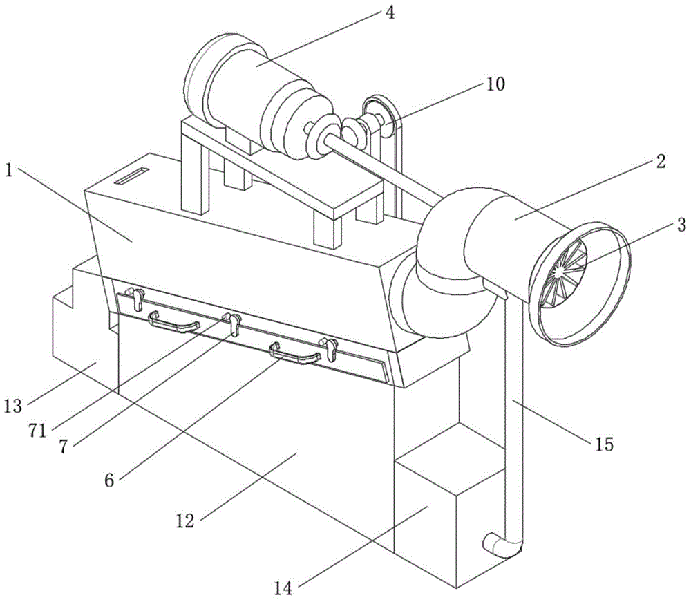
图1为本实用新型提出的一种除尘环保设备的外观结构示意图;Fig. 1 is the appearance structure schematic diagram of a kind of dust removal environmental protection equipment proposed by the utility model;
图2为本实用新型提出的一种除尘环保设备的过滤箱内部结构示意图;Fig. 2 is a schematic diagram of the internal structure of a filter box of a kind of dust removal environmental protection equipment proposed by the utility model;
图3为本实用新型提出的一种除尘环保设备的正面结构示意图;Fig. 3 is a schematic diagram of the front structure of a kind of dust removal and environmental protection equipment proposed by the utility model;
图4为本实用新型提出的一种除尘环保设备的背面结构示意图;Fig. 4 is a schematic diagram of the back structure of a kind of dust removal and environmental protection equipment proposed by the utility model;
图5为本实用新型提出的一种除尘环保设备的除尘滤板结构示意图。Fig. 5 is a structural schematic diagram of a dust removal filter plate of a dust removal environmental protection equipment proposed by the utility model.
图中:过滤箱1、进气管2、涡轮风扇3、驱动电机4、除尘滤板5、密封板51、握把6、锁紧块7、限位块71、传送带8、刷丝81、转动辊9、传动组件10、第一带轮101、同步带102、第二带轮103、第一锥齿轮104、第二锥齿轮105、清洁齿11、循环水箱12、收集箱13、净化水箱14、滤网141、送水管15、增压水泵151、雾化喷头16。In the figure:
具体实施方式Detailed ways
下面将结合本实用新型实施例中的附图,对本实用新型实施例中的技术方案进行清楚、完整地描述,显然,所描述的实施例仅仅是本实用新型一部分实施例,而不是全部的实施例。The technical solutions in the embodiments of the present invention will be clearly and completely described below in conjunction with the accompanying drawings in the embodiments of the present invention. Obviously, the described embodiments are only part of the embodiments of the present invention, not all of them. example.
在本实用新型的描述中,需要理解的是,术语“上”、“下”、“前”、“后”、“左”、“右”、“顶”、“底”、“内”、“外”等指示的方位或位置关系为基于附图所示的方位或位置关系,仅是为了便于描述本实用新型和简化描述,而不是指示或暗示所指的设备或元件必须具有特定的方位、以特定的方位构造和操作,因此不能理解为对本实用新型的限制。In describing the present utility model, it should be understood that the terms "upper", "lower", "front", "rear", "left", "right", "top", "bottom", "inner", The orientation or positional relationship indicated by "outside" is based on the orientation or positional relationship shown in the drawings, which is only for the convenience of describing the utility model and simplifying the description, rather than indicating or implying that the referred device or element must have a specific orientation , are constructed and operated in a specific orientation and therefore cannot be construed as limiting the invention.
实施例一Embodiment one
参照图1-5,一种除尘环保设备,包括倾斜设置的过滤箱1和进气管2,所述过滤箱1顶壁上设有排气口,所述进气管2贯通插设在过滤箱1较高一侧的侧壁上,所述进气管2内转动设有涡轮风扇3,涡轮风扇3主轴向一侧延伸并连接在驱动电机4的输出端上,驱动电机4通过电机支架水平安装在过滤箱1上方,通过涡轮风扇3将环境空气吸入过滤箱1内进行除尘。Referring to Figures 1-5, a dust removal and environmental protection equipment includes a
所述过滤箱1下方设有循环水箱12,循环水箱12一侧设有净化水箱14,净化水箱14与循环水箱12之间设有滤网141,净化水箱14内设有增压水泵151,增压水泵151的输出端上贯通连接有送水管15,送水管15向上延伸贯通进气管2的侧壁设有多个雾化喷头16,通过雾化喷头16将水体雾化,对吸入的灰尘进行降尘,配合滤网141能有效的避免循环水箱12内的循环水将雾化喷头16阻塞,保证雾化喷头16的稳定工作。The bottom of the
所述过滤箱1内腔下部平行设有除尘滤板5,循环水箱12远离净化水箱14的一侧设有收集箱13,所述收集箱13上端贯通过滤箱1与除尘滤板5输出端相连接,通过除尘滤板5对吸收粉尘的水体进行过滤,将粉尘滤下并将水体送回循环水箱12内继续进行粉尘吸收,滤下的粉尘送入收集箱13中收集,方便对粉尘进行回收和处理。The lower part of the inner cavity of the
所述除尘滤板5前侧向前延伸贯穿过滤箱1的侧壁并连接有密封板51,且密封板51靠近过滤箱1的一侧设有相对应的密封圈,所述密封板51前壁上还设有多个握把6,配合密封板51和握把6能方便的将除尘滤板5抽出,方便对除尘滤板5进行清洁,保证除尘滤板5的过滤效果。The front side of the dust
在使用本除尘设备时,启动驱动电机4带动涡轮风扇3转动将带灰尘和粉尘的空气吸入,同时启动增压水泵151将循环水泵入雾化喷头16中雾化喷淋,对空气中的粉尘进行吸收并凝聚成水滴滑落进过滤箱1中,配合除尘滤板5对含有粉尘的水体进行过滤,水体落入循环水箱12中再次进入循环,将灰尘留在除尘滤板5上方并延除尘滤板5滑动直至落入收集箱13中收集,在长时间使用后,可以将除尘滤板5抽出对除尘滤板清洁保证其除尘效果,本除尘设备的除尘滤板5能方便的取出进行清洁,很大程度的提高了除尘设备长时间除尘的能力,降低了检修成本,也避免了仅使用除尘滤网除尘方式需要对除尘滤网的频繁更换。When using this dedusting equipment, start the
本实施例中,如图1-4所示,所述过滤箱1内腔上部转动设有与除尘滤板5相对应的传送带8,传送带8外侧设有与除尘滤板5相匹配的刷丝81,传送带8内转动设有多个转动辊9,其中一个转动辊9与驱动电机4之间连接有传动组件10,通过转动的刷丝81对除尘滤板5进行刷动,避免灰尘在除尘滤板5上聚集影响除尘效果,也能方便的将除尘滤板5上积聚的粉尘刷动到收集箱13中进行收集,提高对粉尘的持续除尘效果。In this embodiment, as shown in Figures 1-4, the upper part of the inner chamber of the
本实施例中,如图1-4所示,所述传动组件10包括第一带轮101和第二带轮103,其中第一带轮101固定套设在转动辊9的转动轴上,第一带轮101和第二带轮103之间连接有同步带102,所述第二带轮103转动安装在电机支架上并同轴连接有第一锥齿轮104,第一锥齿轮104啮合有第二锥齿轮105,第二锥齿轮105固定套设在驱动电机4的输出端上,驱动电机4带动第二锥齿轮105转动,进而带动第一锥齿轮104和第二带轮103转动,再配合同步带102带动第一带轮101转动,带动转动辊9和传送带8转动,保证刷丝81对除尘滤板5的清洁效果。In this embodiment, as shown in Figures 1-4, the
本实施例中,如图1-4所示,所述过滤箱1内腔中靠近除尘滤板5输出端的一侧设有多个与刷丝81相对应的清洁齿11,配合清洁齿11将刷丝81上粘连的粉尘刷落,保障刷丝81的清洁,也保证对粉尘的回收效果,保证灰尘能进入收集箱13内进行收集。In this embodiment, as shown in Figures 1-4, a plurality of cleaning
本实施例中,如图1-5所示,所述过滤箱1前壁上转动设有多个与密封板51相匹配的锁紧块7,通过将锁紧块7转动到密封板51前侧对密封板51进行锁紧,避免除尘滤板5移动影响过滤除尘效果,同时也提高密封板51的密封效果,避免水体溢出,在需要将除尘滤板5取出时,转动锁紧块7即可将密封板51抽出。In this embodiment, as shown in Figures 1-5, a plurality of locking
本实施例中,如图1-3所示,所述过滤箱1前壁上还设有多个与锁紧块7相对应的限位块71,在需要将除尘滤板5取出时,转动锁紧块7至限位块71的位置,对锁紧块7进行限位,不需要人工对锁紧块7的位置进行保持,提高了锁紧块7的使用效果。In this embodiment, as shown in Figures 1-3, a plurality of limit blocks 71 corresponding to the locking blocks 7 are also provided on the front wall of the
以上所述,仅为本实用新型较佳的具体实施方式,但本实用新型的保护范围并不局限于此,任何熟悉本技术领域的技术人员在本实用新型揭露的技术范围内,根据本实用新型的技术方案及其实用新型构思加以等同替换或改变,都应涵盖在本实用新型的保护范围之内。The above is only a preferred embodiment of the utility model, but the scope of protection of the utility model is not limited thereto. Any equivalent replacement or change of the new technical solution and the concept of the utility model shall be covered by the protection scope of the utility model.