CN218456093U - Heat exchange device of battery, battery pack and vehicle - Google Patents

Heat exchange device of battery, battery pack and vehicle Download PDF

Info

Publication number
CN218456093U
CN218456093U CN202222636504.5U CN202222636504U CN218456093U CN 218456093 U CN218456093 U CN 218456093U CN 202222636504 U CN202222636504 U CN 202222636504U CN 218456093 U CN218456093 U CN 218456093U
Authority
CN
China
Prior art keywords
heat exchange
battery
header
collector
sub
Prior art date
Legal status (The legal status is an assumption and is not a legal conclusion. Google has not performed a legal analysis and makes no representation as to the accuracy of the status listed.)
Active
Application number
CN202222636504.5U
Other languages
Chinese (zh)
Inventor
钟日军
蔡耀民
朱瑞元
Current Assignee (The listed assignees may be inaccurate. Google has not performed a legal analysis and makes no representation or warranty as to the accuracy of the list.)
BYD Co Ltd
Original Assignee
BYD Co Ltd
Priority date (The priority date is an assumption and is not a legal conclusion. Google has not performed a legal analysis and makes no representation as to the accuracy of the date listed.)
Filing date
Publication date
Application filed by BYD Co Ltd filed Critical BYD Co Ltd
Priority to CN202222636504.5U priority Critical patent/CN218456093U/en
Application granted granted Critical
Publication of CN218456093U publication Critical patent/CN218456093U/en
Active legal-status Critical Current
Anticipated expiration legal-status Critical

Links

Images

Classifications

    • Y—GENERAL TAGGING OF NEW TECHNOLOGICAL DEVELOPMENTS; GENERAL TAGGING OF CROSS-SECTIONAL TECHNOLOGIES SPANNING OVER SEVERAL SECTIONS OF THE IPC; TECHNICAL SUBJECTS COVERED BY FORMER USPC CROSS-REFERENCE ART COLLECTIONS [XRACs] AND DIGESTS
    • Y02—TECHNOLOGIES OR APPLICATIONS FOR MITIGATION OR ADAPTATION AGAINST CLIMATE CHANGE
    • Y02E—REDUCTION OF GREENHOUSE GAS [GHG] EMISSIONS, RELATED TO ENERGY GENERATION, TRANSMISSION OR DISTRIBUTION
    • Y02E60/00—Enabling technologies; Technologies with a potential or indirect contribution to GHG emissions mitigation
    • Y02E60/10—Energy storage using batteries

Landscapes

  • Secondary Cells (AREA)

Abstract

本实用新型公开了一种电池的换热装置、电池包以及车辆,换热装置包括:第一集流管;换热管和第二集流管,所述换热管连接在所述第一集流管和所述第二集流管之间,且所述换热管连通所述第一集流管和所述第二集流管,所述换热管、所述第一集流管和所述第二集流管之间形成换热介质可流动的换热介质流道,所述第一集流管和/或所述第二集流管适于与所述电池接触。由此,本申请换热装置的第一集流管和/或第二集流管能够与电池换热,可以提升换热装置的换热效率,并且,第一集流管和第二集流管占据空间小,有利于提升电池包内空间利用率。
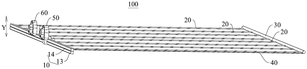
Figure 202222636504

The utility model discloses a battery heat exchange device, a battery pack and a vehicle. The heat exchange device comprises: a first collector; a heat exchange tube and a second collector; the heat exchange tube is connected to the first Between the header and the second header, and the heat exchange tube communicates with the first header and the second header, the heat exchange tube, the first header A heat exchange medium passage through which a heat exchange medium can flow is formed between the second header and the second header, and the first header and/or the second header are adapted to be in contact with the battery. Therefore, the first header and/or the second header of the heat exchange device of the present application can exchange heat with the battery, which can improve the heat exchange efficiency of the heat exchange device, and the first header and the second header The tube occupies a small space, which is conducive to improving the space utilization rate in the battery pack.

Figure 202222636504

Description

电池的换热装置、电池包以及车辆Battery heat exchange device, battery pack and vehicle

技术领域technical field

本实用新型涉及电池领域,尤其是涉及一种电池的换热装置、电池包以及车辆。The utility model relates to the battery field, in particular to a battery heat exchange device, a battery pack and a vehicle.

背景技术Background technique

电池包内设置有电池,电池是一个温度要求严苛的零部件,电池长时间地高温或者低温工作都会降低电池的使用寿命,产生安全隐患。因此,如何将电池的工作温度维持在一个合适的温度是一个行业痛点问题。The battery pack is equipped with a battery. The battery is a component with strict temperature requirements. Working at high temperature or low temperature for a long time will reduce the service life of the battery and cause potential safety hazards. Therefore, how to maintain the working temperature of the battery at an appropriate temperature is a pain point in the industry.

相关技术中,使用换热器对电池进行加热或降温,将电池维持在一个稳定又合适的温度。换热器包括进出口接头、换热管和集流管组件,集流管组件连接在进出口接头和换热管之间,集流管组件连通进出口接头和换热管。但是,集流管组件无法与电池直接接触,集流管组件无法对电池进行冷却,换热介质流过集流管组件时会造成冷量损失,降低了换热器的换热效率,另外,集流管组件占据空间大,不利于电池包内空间利用率。In the related art, a heat exchanger is used to heat or cool down the battery, so as to maintain the battery at a stable and suitable temperature. The heat exchanger includes inlet and outlet joints, heat exchange tubes and a header assembly, the header assembly is connected between the inlet and outlet joints and the heat exchange tubes, and the header assembly communicates with the inlet and outlet joints and the heat exchange tubes. However, the header assembly cannot be in direct contact with the battery, and the header assembly cannot cool the battery. When the heat exchange medium flows through the header assembly, it will cause a loss of cooling capacity, which reduces the heat exchange efficiency of the heat exchanger. In addition, The collector assembly occupies a large space, which is not conducive to the utilization of the space in the battery pack.

实用新型内容Utility model content

本实用新型旨在至少解决现有技术中存在的技术问题之一。为此,本实用新型的一个目的在于提出了一种电池的换热装置,该换热装置的换热效率得到提升,且有利于提升电池包内空间利用率。The utility model aims at at least solving one of the technical problems existing in the prior art. Therefore, an object of the present invention is to provide a heat exchange device for a battery, the heat exchange efficiency of the heat exchange device is improved, and it is beneficial to improve the utilization rate of the space inside the battery pack.

本实用新型进一步地提出了一种电池包。The utility model further provides a battery pack.

本实用新型进一步地提出了一种车辆。The utility model further provides a vehicle.

根据本实用新型的电池的换热装置,包括:According to the battery heat exchange device of the present invention, comprising:

第一集流管;first header;

换热管和第二集流管,所述换热管连接在所述第一集流管和所述第二集流管之间,且所述换热管连通所述第一集流管和所述第二集流管,所述换热管、所述第一集流管和所述第二集流管之间形成换热介质可流动的换热介质流道,所述第一集流管和/或所述第二集流管适于与所述电池接触。A heat exchange tube and a second header, the heat exchange tube is connected between the first header and the second header, and the heat exchange tube communicates with the first header and the second header The second header, the heat exchange tube, the first header and the second header form a heat exchange medium channel through which the heat exchange medium can flow, and the first header A tube and/or said second header is adapted to be in contact with said cells.

根据本实用新型的电池的换热装置,通过第一集流管和/或第二集流管与电池接触换热,避免冷量在第一集流管和/或第二集流管损失,可以提升换热装置的换热效率,并且,第一集流管和第二集流管体积小,第一集流管和第二集流管占据空间小,有利于提升电池包内空间利用率。According to the battery heat exchange device of the present invention, the first header and/or the second header are in contact with the battery to exchange heat, so as to avoid the loss of cooling capacity in the first header and/or the second header, The heat exchange efficiency of the heat exchange device can be improved, and the volume of the first header and the second header is small, and the space occupied by the first header and the second header is small, which is conducive to improving the space utilization rate in the battery pack .

在本实用新型的一些示例中,所述换热介质流道的两端分别形成换热介质进口、换热介质出口,所述换热介质进口和换热介质出口设于所述第一集流管。In some examples of the present utility model, the heat exchange medium inlet and the heat exchange medium outlet are respectively formed at both ends of the heat exchange medium channel, and the heat exchange medium inlet and the heat exchange medium outlet are arranged in the first header Tube.

在本实用新型的一些示例中,所述第一集流管和/或所述第二集流管与所述电池面面接触。In some examples of the present invention, the first collector and/or the second collector are in surface contact with the battery.

在本实用新型的一些示例中,所述换热管为多个,多个所述换热管沿所述第一集流管的长度方向排布。In some examples of the present invention, there are multiple heat exchange tubes, and the multiple heat exchange tubes are arranged along the length direction of the first header.

在本实用新型的一些示例中,所述第一集流管包括:第一子集流管和第二子集流管,所述第一子集流管设有所述换热介质进口,所述第二子集流管设有所述换热介质出口,所述第一子集流管适于与多个所述换热管中的一部分所述换热管连通,所述第二子集流管与多个所述换热管中的另一部分所述换热管连通。In some examples of the present utility model, the first header includes: a first sub-collector and a second sub-collector, the first sub-collector is provided with the heat exchange medium inlet, and the The second sub-collector is provided with the heat exchange medium outlet, the first sub-collector is adapted to communicate with a part of the heat exchange tubes in the plurality of heat exchange tubes, and the second sub-collector The flow tube communicates with another part of the plurality of heat exchange tubes.

在本实用新型的一些示例中,沿所述第一子集流管长度方向,所述第一子集流管适于与靠近外侧设置的至少一个所述换热管连通。In some examples of the present invention, along the length direction of the first sub-collector, the first sub-collector is adapted to communicate with at least one heat exchange tube disposed near the outside.

在本实用新型的一些示例中,所述第一子集流管具有第一连通孔,所述第二子集流管具有与所述第一连通孔连通的第二连通孔,所述第二子集流管还具有与所述一部分所述换热管连通的第三连通孔。In some examples of the present utility model, the first sub-collector has a first communication hole, the second sub-collector has a second communication hole communicated with the first communication hole, and the second The sub-collector further has a third communicating hole communicating with the part of the heat exchange tubes.

在本实用新型的一些示例中,所述第二子集流管还具有与所述另一部分所述换热管连通的第四连通孔。In some examples of the present utility model, the second sub-collector further has a fourth communicating hole communicating with the other part of the heat exchange tube.

在本实用新型的一些示例中,所述第二子集流管内设有分隔件,所述分隔件将所述第二子集流管内分隔为第一集流腔和第二集流腔,所述第二连通孔、所述第三连通孔均与所述第一集流腔对应连通,所述第四连通孔均与所述第二集流腔对应连通。In some examples of the present utility model, a partition is provided in the second sub-collector, and the partition divides the second sub-collector into a first manifold and a second manifold, so Both the second communication hole and the third communication hole are in communication with the first manifold, and the fourth communication holes are in communication with the second manifold.

在本实用新型的一些示例中,所述第一集流腔为多个,沿所述第一子集流管长度方向,多个所述第一集流腔设于所述第二集流腔的至少一侧。In some examples of the present utility model, there are multiple first manifolds, and along the length direction of the first sub-manifold, multiple first manifolds are arranged in the second manifold at least one side of the

在本实用新型的一些示例中,所述的电池的换热装置,还包括:进口接头和出口接头,所述进口接头和所述出口接头均设于所述第一集流管,且所述进口接头与所述换热介质进口连通,所述出口接头与所述换热介质出口连通。In some examples of the present invention, the heat exchange device of the battery further includes: an inlet joint and an outlet joint, both of the inlet joint and the outlet joint are arranged in the first header, and the The inlet joint communicates with the heat exchange medium inlet, and the outlet joint communicates with the heat exchange medium outlet.

在本实用新型的一些示例中,所述的电池的换热装置,还包括:均温板,所述均温板与所述换热管固定连接且位于所述换热管靠近所述电池一侧。In some examples of the present utility model, the heat exchange device of the battery further includes: a uniform temperature plate, which is fixedly connected to the heat exchange tube and located at the side of the heat exchange tube close to the battery. side.

根据本实用新型的电池包,包括:According to the battery pack of the utility model, comprising:

电池;Battery;

换热装置,所述换热装置与所述电池换热,所述换热装置为上述的电池的换热装置。A heat exchange device, the heat exchange device exchanges heat with the battery, and the heat exchange device is the above-mentioned heat exchange device of the battery.

在本实用新型的一些示例中,所述的电池包,还包括:外壳,所述电池和所述换热装置均设于所述外壳内。In some examples of the present invention, the battery pack further includes: a casing, and the battery and the heat exchange device are both arranged in the casing.

根据本实用新型的车辆,包括上述的电池包。A vehicle according to the present invention includes the above-mentioned battery pack.

本实用新型的附加方面和优点将在下面的描述中部分给出,部分将从下面的描述中变得明显,或通过本实用新型的实践了解到。Additional aspects and advantages of the invention will be set forth in the description which follows, and in part will be obvious from the description, or may be learned by practice of the invention.

附图说明Description of drawings

本实用新型的上述和/或附加的方面和优点从结合下面附图对实施例的描述中将变得明显和容易理解,其中:The above and/or additional aspects and advantages of the present utility model will become apparent and easy to understand from the description of the embodiments in conjunction with the following drawings, wherein:

图1是根据本实用新型实施例的换热装置的示意图;Fig. 1 is a schematic diagram of a heat exchange device according to an embodiment of the present invention;

图2是根据本实用新型实施例的换热装置的另一个角度示意图;Fig. 2 is a schematic diagram of another angle of the heat exchange device according to the embodiment of the present invention;

图3是根据本实用新型实施例的换热装置的第一集流管的示意图;3 is a schematic diagram of a first header of a heat exchange device according to an embodiment of the present invention;

图4是根据本实用新型实施例的换热装置的第二子集流管的示意图;4 is a schematic diagram of a second sub-collector of a heat exchange device according to an embodiment of the present invention;

图5是根据本实用新型实施例的换热装置的第二子集流管的另一个角度示意图;Fig. 5 is another perspective schematic diagram of the second sub-collector of the heat exchange device according to the embodiment of the present invention;

图6是根据本实用新型实施例的换热装置的第二子集流管的另一个角度示意图;Fig. 6 is another perspective schematic diagram of the second sub-collector of the heat exchange device according to the embodiment of the present invention;

图7是根据本实用新型实施例的换热装置的第二子集流管的另一个角度示意图;Fig. 7 is another perspective schematic view of the second sub-collector of the heat exchange device according to the embodiment of the present invention;

图8是根据本实用新型实施例的换热装置的第一子集流管的示意图。Fig. 8 is a schematic diagram of a first sub-collector of a heat exchange device according to an embodiment of the present invention.

附图标记:Reference signs:

换热装置100;Heat exchange device 100;

第一集流管10;换热介质进口11;换热介质出口12;The first header 10; the heat exchange medium inlet 11; the heat exchange medium outlet 12;

第一子集流管13;第一连通孔131;The first sub-collector 13; the first communication hole 131;

第二子集流管14;第二连通孔141;第三连通孔142;第四连通孔143;分隔件144;第一集流腔145;第二集流腔146;The second sub-collector 14; the second communication hole 141; the third communication hole 142; the fourth communication hole 143; the partition 144; the first manifold 145; the second manifold 146;

换热管20;Heat exchange tube 20;

第二集流管30;second header 30;

均温板40;进口接头50;出口接头60。Vapor chamber 40; inlet joint 50; outlet joint 60.

具体实施方式Detailed ways

下面详细描述本实用新型的实施例,所述实施例的示例在附图中示出,其中自始至终相同或类似的标号表示相同或类似的元件或具有相同或类似功能的元件。下面通过参考附图描述的实施例是示例性的,仅用于解释本实用新型,而不能理解为对本实用新型的限制。Embodiments of the present invention are described in detail below, examples of which are shown in the drawings, wherein the same or similar reference numerals represent the same or similar elements or elements having the same or similar functions throughout. The embodiments described below with reference to the accompanying drawings are exemplary and are only used to explain the present utility model, but should not be construed as limiting the present utility model.

下面参考图1-图8描述根据本实用新型实施例的电池的换热装置100,换热装置100可以安装于电池包内,换热装置100可以与电池进行热交换,从而使电池的工作温度维持在适宜的温度。但本实用新型不限于此,换热装置100也可以用于与其他需要加热或冷却的元件进行换热。本申请以换热装置100与电池进行热交换为例进行说明。The heat exchange device 100 of the battery according to the embodiment of the present invention will be described below with reference to FIGS. Maintain a suitable temperature. But the present invention is not limited thereto, and the heat exchange device 100 can also be used to exchange heat with other elements that need to be heated or cooled. In this application, the heat exchange between the heat exchange device 100 and the battery is taken as an example for description.

如图1-图8所示,根据本实用新型实施例的换热装置100包括:第一集流管10、换热管20和第二集流管30。换热管20可以构造为扁管,第二集流管30可以构造为圆管或多边形管,第一集流管10和第二集流管30中的一个设置有换热介质进口11和换热介质出口12,本申请以第一集流管10设置有换热介质进口11和换热介质出口12为例进行说明。换热介质可以从换热介质进口11流入第一集流管10内,流入第一集流管10内的换热介质可以从换热介质出口12流出第一集流管10,换热介质可以为液态换热介质或气态换热介质,换热介质的具体类型根据实际需要进行合理选择。换热管20连接在第一集流管10和第二集流管30之间,进一步地,换热管20可以焊接在第一集流管10和第二集流管30之间,换热管20的一端与第一集流管10焊接,换热管20的另一端与第二集流管30焊接,且换热管20连通第一集流管10和第二集流管30,换热管20、第一集流管10和第二集流管30之间形成换热介质可流动的换热介质流道,换热介质流道连通换热介质进口11和换热介质出口12,第一集流管10和/或第二集流管30适于与电池接触,也可以理解为,第一集流管10适于与电池接触,或者第二集流管30适于与电池接触,或者第一集流管10和第二集流管30同时适于与电池接触。As shown in FIGS. 1-8 , a heat exchange device 100 according to an embodiment of the present invention includes: a first header 10 , a heat exchange tube 20 and a second header 30 . The heat exchange tube 20 can be configured as a flat tube, the second header 30 can be configured as a circular tube or a polygonal tube, and one of the first header 10 and the second header 30 is provided with a heat exchange medium inlet 11 and a heat exchange medium. For the heat medium outlet 12 , the present application takes the first header 10 provided with the heat exchange medium inlet 11 and the heat exchange medium outlet 12 as an example for illustration. The heat exchange medium can flow into the first header 10 from the heat exchange medium inlet 11, and the heat exchange medium flowing into the first header 10 can flow out of the first header 10 from the heat exchange medium outlet 12, and the heat exchange medium can be It is a liquid heat exchange medium or a gaseous heat exchange medium, and the specific type of heat exchange medium is reasonably selected according to actual needs. The heat exchange tube 20 is connected between the first header 10 and the second header 30, further, the heat exchange tube 20 can be welded between the first header 10 and the second header 30, the heat exchange One end of the tube 20 is welded to the first header 10, the other end of the heat exchange tube 20 is welded to the second header 30, and the heat exchange tube 20 communicates with the first header 10 and the second header 30, and A heat exchange medium channel through which the heat exchange medium can flow is formed between the heat pipe 20 , the first header 10 and the second header 30 , and the heat exchange medium channel is connected to the heat exchange medium inlet 11 and the heat exchange medium outlet 12 , The first collector 10 and/or the second collector 30 are adapted to be in contact with the battery. It can also be understood that the first collector 10 is suitable for contact with the battery, or the second collector 30 is suitable for contact with the battery. , or both the first header 10 and the second header 30 are adapted to be in contact with the battery.

其中,换热装置100和电池均设置于电池包内,换热装置100和电池安装于电池包内后,换热装置100的第一集流管10和换热管20均与电池接触。换热介质从换热介质进口11流入换热介质流道,最终换热介质流道内的换热介质从换热介质出口12流出。换热介质在换热装置100内流动过程中可以与电池换热,从而实现加热电池和冷却电池的效果。例如:当电池需要降温时,可以使温度较低的换热介质从换热介质进口11流入换热装置100,实现冷却电池的效果,当电池需要加热时,可以使温度较高的换热介质从换热介质进口11流入换热装置100,实现加热电池的效果,从而实现将电池的工作温度维持在适宜温度的效果。在本申请中,通过使第一集流管10和/或第二集流管30与电池接触,换热介质流过第一集流管10和/或第二集流管30时能够与电池换热,避免热量在第一集流管10和/或第二集流管30散失,可以提升换热装置100的换热效率,并且,第一集流管10和第二集流管30体积小,第一集流管10和第二集流管30占据空间小,换热装置100安装于电池包内后,换热装置100占用电池包内空间减小,有利于提升电池包内空间利用率。Wherein, the heat exchange device 100 and the battery are arranged in the battery pack, and after the heat exchange device 100 and the battery are installed in the battery pack, the first collector 10 and the heat exchange tube 20 of the heat exchange device 100 are in contact with the battery. The heat exchange medium flows into the heat exchange medium flow channel from the heat exchange medium inlet 11 , and finally the heat exchange medium in the heat exchange medium flow channel flows out from the heat exchange medium outlet 12 . The heat exchange medium can exchange heat with the battery while flowing in the heat exchange device 100 , so as to achieve the effects of heating and cooling the battery. For example: when the battery needs to cool down, the heat exchange medium with a lower temperature can flow into the heat exchange device 100 from the heat exchange medium inlet 11 to realize the effect of cooling the battery; when the battery needs to be heated, the heat exchange medium with a higher temperature can be made to The heat exchange medium flows into the heat exchange device 100 from the heat exchange medium inlet 11 to achieve the effect of heating the battery, thereby realizing the effect of maintaining the working temperature of the battery at an appropriate temperature. In this application, by making the first header 10 and/or the second header 30 contact with the battery, the heat exchange medium can contact the battery when flowing through the first header 10 and/or the second header 30 Heat exchange, avoiding heat loss in the first header 10 and/or the second header 30, can improve the heat exchange efficiency of the heat exchange device 100, and the volume of the first header 10 and the second header 30 Small, the first header 10 and the second header 30 occupy a small space. After the heat exchange device 100 is installed in the battery pack, the space occupied by the heat exchange device 100 in the battery pack is reduced, which is conducive to improving the utilization of the space in the battery pack. Rate.

由此,通过第一集流管10和/或第二集流管30与电池接触换热,使第一集流管10和/或第二集流管30参与换热,避免热量、冷量在第一集流管10和/或第二集流管30损失,可以提升换热装置100的换热效率,并且,第一集流管10和第二集流管30体积小,第一集流管10和第二集流管30占据空间小,有利于提升电池包内空间利用率。Thus, through the first header 10 and/or the second header 30 contacting the battery for heat exchange, the first header 10 and/or the second header 30 participate in heat exchange, avoiding heat and cold The loss in the first header 10 and/or the second header 30 can improve the heat exchange efficiency of the heat exchange device 100, and the volume of the first header 10 and the second header 30 is small, and the first header The space occupied by the flow tube 10 and the second flow tube 30 is small, which is beneficial to improve the utilization rate of the space in the battery pack.

在本实用新型的一些实施例中,换热介质流道的两端分别形成换热介质进口11、换热介质出口12,换热介质进口11和换热介质出口12设置于第一集流管10。其中,换热装置100和电池均设置于电池包内,换热装置100和电池安装于电池包内后,换热装置100的第一集流管10和换热管20均与电池接触。换热介质从换热介质进口11流入第一集流管10,第一集流管10内的换热介质会沿着换热管20流入第二集流管30,第二集流管30内的换热介质可以沿着换热管20流入第一集流管10,最终第一集流管10内的换热介质从换热介质出口12流出。换热介质在换热装置100内流动过程中可以与电池换热,从而实现加热电池和冷却电池的效果。例如:当电池需要降温时,可以使温度较低的换热介质从换热介质进口11流入换热装置100,实现冷却电池的效果,当电池需要加热时,可以使温度较高的换热介质从换热介质进口11流入换热装置100,实现加热电池的效果,从而实现将电池的工作温度维持在适宜温度的效果。在本申请中,通过使第一集流管10和/或第二集流管30与电池接触,换热介质流过第一集流管10和/或第二集流管30时能够与电池换热,避免热量在第一集流管10和/或第二集流管30散失,可以提升换热装置100的换热效率,并且,第一集流管10和第二集流管30体积小,第一集流管10和第二集流管30占据空间小,换热装置100安装于电池包内后,换热装置100占用电池包内空间减小,有利于提升电池包内空间利用率。In some embodiments of the present utility model, the heat exchange medium inlet 11 and the heat exchange medium outlet 12 are respectively formed at both ends of the heat exchange medium flow channel, and the heat exchange medium inlet 11 and the heat exchange medium outlet 12 are arranged in the first header 10. Wherein, the heat exchange device 100 and the battery are arranged in the battery pack, and after the heat exchange device 100 and the battery are installed in the battery pack, the first collector 10 and the heat exchange tube 20 of the heat exchange device 100 are in contact with the battery. The heat exchange medium flows into the first header 10 from the heat exchange medium inlet 11, and the heat exchange medium in the first header 10 flows into the second header 30 along the heat exchange tubes 20, and the second header 30 The heat exchange medium can flow into the first header 10 along the heat exchange tube 20 , and finally the heat exchange medium in the first header 10 flows out from the heat exchange medium outlet 12 . The heat exchange medium can exchange heat with the battery while flowing in the heat exchange device 100 , so as to achieve the effects of heating and cooling the battery. For example: when the battery needs to cool down, the heat exchange medium with a lower temperature can flow into the heat exchange device 100 from the heat exchange medium inlet 11 to realize the effect of cooling the battery; when the battery needs to be heated, the heat exchange medium with a higher temperature can be made to The heat exchange medium flows into the heat exchange device 100 from the heat exchange medium inlet 11 to achieve the effect of heating the battery, thereby realizing the effect of maintaining the working temperature of the battery at an appropriate temperature. In this application, by making the first header 10 and/or the second header 30 contact with the battery, the heat exchange medium can contact the battery when flowing through the first header 10 and/or the second header 30 Heat exchange, avoiding heat loss in the first header 10 and/or the second header 30, can improve the heat exchange efficiency of the heat exchange device 100, and the volume of the first header 10 and the second header 30 Small, the first header 10 and the second header 30 occupy a small space. After the heat exchange device 100 is installed in the battery pack, the space occupied by the heat exchange device 100 in the battery pack is reduced, which is conducive to improving the utilization of the space in the battery pack. Rate.

在本实用新型的一些实施例中,第一集流管10和/或第二集流管30与电池面面接触,也就是说,第一集流管10与电池面面接触,或者第二集流管30与电池面面接触,或者第一集流管10和第二集流管30均与电池面面接触。其中,通过第一集流管10和第二集流管30中的至少一个与电池面面接触,能够增加换热装置100与电池接触面积,换热介质在换热装置100内流动时,能够更加快速将电池热量带走,可以进一步提升换热装置100的换热效率。In some embodiments of the present utility model, the first collector 10 and/or the second collector 30 are in surface contact with the battery, that is to say, the first collector 10 is in surface contact with the battery, or the second collector 10 is in surface contact with the battery. The collector 30 is in surface contact with the battery, or both the first collector 10 and the second collector 30 are in surface contact with the battery. Wherein, at least one of the first header 10 and the second header 30 is in surface contact with the battery, the contact area between the heat exchange device 100 and the battery can be increased, and when the heat exchange medium flows in the heat exchange device 100, it can Taking away the battery heat more quickly can further improve the heat exchange efficiency of the heat exchange device 100 .

在本实用新型的一些实施例中,如图1和图2所示,换热管20可以设置为多个,多个换热管20沿第一集流管10的长度方向排布,当换热装置100以图2中方向放置时,第一集流管10的长度方向是指图2中的X方向。通过设置多个换热管20,多个换热管20能够同时与电池的不同区域换热,可以使电池不同区域的温度均匀,从而可以有效避免电池的局部出现过温情况,进而使换热装置100更好地冷却或加热电池。In some embodiments of the present utility model, as shown in Fig. 1 and Fig. 2, multiple heat exchange tubes 20 can be provided, and the plurality of heat exchange tubes 20 are arranged along the length direction of the first header 10. When the heat device 100 is placed in the direction shown in FIG. 2 , the length direction of the first header 10 refers to the X direction in FIG. 2 . By arranging multiple heat exchange tubes 20, multiple heat exchange tubes 20 can exchange heat with different areas of the battery at the same time, which can make the temperature of different areas of the battery uniform, thereby effectively avoiding local overheating of the battery, thereby enabling heat exchange The device 100 better cools or heats the battery.

在本实用新型的一些实施例中,如图1和图2所示,第一集流管10可以包括:第一子集流管13和第二子集流管14,第一子集流管13和第二子集流管14均可以设置为四边形管,第一子集流管13设置有换热介质进口11,第二子集流管14设置有换热介质出口12,第一子集流管13适于与多个换热管20中的一部分换热管20连通,第二子集流管14与多个换热管20中的另一部分换热管20连通。其中,如图2所示,多个换热管20的一端均与第二集流管30连通,多个换热管20中的一部分换热管20的另一端与第一子集流管13连通,多个换热管20中的另一部分换热管20的另一端与第二子集流管14连通。In some embodiments of the present utility model, as shown in Fig. 1 and Fig. 2, the first header 10 may include: a first sub-collector 13 and a second sub-collector 14, the first sub-collector 13 and the second sub-collector 14 can be set as quadrangular tubes, the first sub-collector 13 is provided with a heat exchange medium inlet 11, the second sub-collector 14 is provided with a heat exchange medium outlet 12, the first sub-collector The flow tube 13 is adapted to communicate with a part of the heat exchange tubes 20 in the plurality of heat exchange tubes 20 , and the second sub-collector 14 communicates with another part of the heat exchange tubes 20 in the plurality of heat exchange tubes 20 . Wherein, as shown in FIG. 2 , one end of a plurality of heat exchange tubes 20 communicates with the second header 30 , and the other end of a part of the heat exchange tubes 20 in the plurality of heat exchange tubes 20 communicates with the first sub-collector 13 The other end of another part of the heat exchange tubes 20 in the plurality of heat exchange tubes 20 communicates with the second sub-collector 14 .

当换热介质从换热介质进口11流入第一子集流管13时,第一子集流管13内的换热介质从与第一子集流管13连通的一部分换热管20流入第二集流管30内,第二集流管30内的换热介质从与第二集流管30连通的另一部分换热管20流入第二子集流管14,最终换热介质从第二子集流管14的换热介质出口12流出换热装置100。如此设置能够实现换热介质在换热装置100内的循环流动,电池的热量可以源源不断被换热介质带走,从而实现快速降低电池温度效果,并且,当加热电池时,换热介质可以持续加热电池,从而可以保证电池在适宜的温度下工作。When the heat exchange medium flows into the first sub-collector 13 from the heat exchange medium inlet 11, the heat exchange medium in the first sub-collector 13 flows into the first sub-collector 13 from a part of the heat exchange tubes 20 communicating with the first sub-collector 13. In the second header 30, the heat exchange medium in the second header 30 flows into the second sub-collector 14 from another part of the heat exchange tube 20 communicated with the second header 30, and finally the heat exchange medium flows from the second The heat exchange medium outlet 12 of the sub-collector 14 flows out of the heat exchange device 100 . Such setting can realize the circulating flow of the heat exchange medium in the heat exchange device 100, and the heat of the battery can be continuously taken away by the heat exchange medium, so as to realize the effect of rapidly reducing the temperature of the battery, and, when the battery is heated, the heat exchange medium can continuously Heat the battery to ensure that the battery works at a suitable temperature.

在本实用新型的一些实施例中,如图2所示,沿第一子集流管13长度方向,第一子集流管13适于与靠近外侧设置的至少一个换热管20连通,进一步地,第一子集流管13适于通过第二子集流管14与靠近外侧设置的至少一个换热管20连通。例如:如图2所示,第一子集流管13适于与沿第一子集流管13长度方向靠近一侧设置的两个换热管20连通,且第一子集流管13还适于与沿第一子集流管13长度方向靠近另一侧设置的两个换热管20连通,第一子集流管13适于与四个换热管20连通。In some embodiments of the present invention, as shown in FIG. 2, along the length direction of the first sub-collector 13, the first sub-collector 13 is adapted to communicate with at least one heat exchange tube 20 disposed near the outside, further Specifically, the first sub-collector 13 is adapted to communicate with at least one heat exchange tube 20 disposed near the outside through the second sub-collector 14 . For example: as shown in Figure 2, the first sub-collector 13 is adapted to communicate with two heat exchange tubes 20 arranged on one side along the length direction of the first sub-collector 13, and the first sub-collector 13 also The first sub-collector 13 is adapted to communicate with the two heat exchange tubes 20 disposed near the other side along the length direction of the first sub-collector 13 , and the first sub-collector 13 is adapted to communicate with four heat exchange tubes 20 .

其中,电池构造为长电池,电池沿长度方向的两端分别设置电池的正极和负极时,电池沿长度方向两端的温度会比电池中部位置处的温度高,因此电池在降温时首先需要考虑的则是电池两端的温度。通过使用本申请的换热装置100,换热管20沿垂直于电池的长度方向相对电池布置时,沿第一子集流管13长度方向,靠近外侧设置的换热管20与电池的两端对应设置,位于中部的换热管20与电池的中部位置对应设置,进一步地,与第二子集流管14对应连通的换热管20与电池的中部位置对应设置。当换热介质从换热介质进口11流入第一子集流管13时,第一子集流管13内的换热介质分成两路分别朝向第一子集流管13长度方向的两端流动,然后换热介质流入沿第一子集流管13长度方向靠近外侧设置的换热管20,然后换热介质从与第一子集流管13连通的换热管20流入第二集流管30内,第二集流管30内的换热介质从与第二集流管30连通的换热管20流入第二子集流管14,最终换热介质从第二子集流管14的换热介质出口12流出换热装置100。Among them, the battery is constructed as a long battery, and when the positive and negative electrodes of the battery are respectively installed at the two ends of the battery along the length direction, the temperature at the two ends of the battery along the length direction will be higher than the temperature at the middle of the battery, so the first thing to consider when cooling down the battery is the temperature at both ends of the battery. By using the heat exchange device 100 of the present application, when the heat exchange tube 20 is arranged relative to the battery along the length direction perpendicular to the battery, along the length direction of the first sub-collector 13, the heat exchange tube 20 disposed near the outside and the two ends of the battery Correspondingly, the heat exchange tube 20 in the middle is arranged corresponding to the middle position of the battery, and further, the heat exchange tube 20 corresponding to the second sub-collector 14 is arranged corresponding to the middle position of the battery. When the heat exchange medium flows into the first sub-collector 13 from the heat exchange medium inlet 11, the heat exchange medium in the first sub-collector 13 divides into two paths and flows towards the two ends of the first sub-collector 13 in the length direction. , and then the heat exchange medium flows into the heat exchange tube 20 arranged near the outside along the length direction of the first sub-collector 13, and then the heat exchange medium flows into the second header from the heat exchange tube 20 communicating with the first sub-collector 13 30, the heat exchange medium in the second header 30 flows into the second sub-collector 14 from the heat exchange tube 20 communicating with the second header 30, and finally the heat exchange medium flows from the second sub-collector 14 The heat exchange medium outlet 12 flows out of the heat exchange device 100 .

需要说明的是,使用本申请的换热装置100对电池进行冷却或加热,换热介质首先流入靠近电池端部设置换热管20,靠近电池端部设置换热管20换热效率高,靠近电池端部设置的换热管20内换热介质能够快速与电池的端部位置换热,然后换热介质通过第二集流管30流入与电池中部位置对应的换热管20,此时换热介质换热效率降低,换热介质也可以与电池换热,最终换热介质从换热介质出口12流出换热装置100。这样设置能够使换热效率高时的换热介质先流动至电池的两端位置,可以使换热效率高时的换热介质先流动电池发热多的位置,从而更有利于缩小电池不同区域温差,进而使电池的温度更加均匀。It should be noted that when using the heat exchange device 100 of the present application to cool or heat the battery, the heat exchange medium first flows into the heat exchange tube 20 disposed near the end of the battery, and the heat exchange tube 20 disposed near the end of the battery has high heat exchange efficiency and is close to the end of the battery. The heat exchange medium in the heat exchange tube 20 provided at the end of the battery can quickly exchange heat with the end of the battery, and then the heat exchange medium flows into the heat exchange tube 20 corresponding to the middle position of the battery through the second collector 30. The heat exchange efficiency of the heat medium decreases, and the heat exchange medium can also exchange heat with the battery, and finally the heat exchange medium flows out of the heat exchange device 100 from the heat exchange medium outlet 12 . This setting can make the heat exchange medium flow to the two ends of the battery first when the heat exchange efficiency is high, and can make the heat exchange medium flow first to the position where the battery generates more heat when the heat exchange efficiency is high, which is more conducive to reducing the temperature difference between different areas of the battery , so that the temperature of the battery is more uniform.

在本实用新型的一些实施例中,如图8所示,第一子集流管13具有第一连通孔131,第一连通孔131靠近第一子集流管13的端部设置,如图6所示,第二子集流管14具有与第一连通孔131连通的第二连通孔141,第二连通孔141靠近第二子集流管14的端部设置,第一连通孔131和第二连通孔141均可以设置为多个,例如:第一连通孔131和第二连通孔141均设置为两个,两个第一连通孔131分别靠近第一子集流管13的两端设置,两个第二连通孔141分别靠近第二子集流管14的两端设置,第一连通孔131和第二连通孔141一一对应连通,进一步地,如图4所示,第二子集流管14还具有与一部分换热管20连通的第三连通孔142,其中,与第一子集流管13连通的换热管20通过第三连通孔142与第二子集流管14连通。第一子集流管13内的换热介质通过第一连通孔131、第二连通孔141流入第二子集流管14,第二子集流管14内的换热介质可以通过第三连通孔142流入与第一子集流管13对应连通的换热管20内,从而实现第一子集流管13与对应换热管20连通效果。In some embodiments of the present utility model, as shown in FIG. 8, the first sub-collector 13 has a first communication hole 131, and the first communication hole 131 is arranged near the end of the first sub-collector 13, as shown in FIG. 6, the second sub-collector 14 has a second communication hole 141 communicating with the first communication hole 131, the second communication hole 141 is arranged near the end of the second sub-collector 14, the first communication hole 131 and The second communication holes 141 can be set in multiples, for example: the first communication holes 131 and the second communication holes 141 are both set to two, and the two first communication holes 131 are respectively close to the two ends of the first sub-collector 13 Setting, two second communication holes 141 are respectively provided near the two ends of the second sub-collector 14, and the first communication holes 131 and the second communication holes 141 are connected in one-to-one correspondence. Further, as shown in FIG. 4 , the second The sub-collector 14 also has a third communication hole 142 communicating with a part of the heat exchange tubes 20, wherein the heat exchange tube 20 communicated with the first sub-collector 13 is connected to the second sub-collector through the third communication hole 142. 14 connected. The heat exchange medium in the first sub-collector 13 flows into the second sub-collector 14 through the first communication hole 131 and the second communication hole 141, and the heat exchange medium in the second sub-collector 14 can pass through the third communication hole 141. The holes 142 flow into the heat exchange tubes 20 corresponding to the first sub-collectors 13 , so as to realize the communication effect between the first sub-collectors 13 and the corresponding heat exchange tubes 20 .

在本实用新型的一些实施例中,如图4所示,第二子集流管14还具有与另一部分换热管20连通的第四连通孔143,需要说明的是,与第二子集流管14连通的换热管20通过第四连通孔143与第二子集流管14连通,第四连通孔143可以设置为多个,与第二子集流管14连通的换热管20也可以设置为多个,多个第四连通孔143与多个换热管20一一对应连通,例如:第四连通孔143可以设置为四个,与第二子集流管14连通的换热管20也设置为四个。通过设置第四连通孔143,与第二子集流管14连通的换热管20内的换热介质能够通过第四连通孔143流入第二子集流管14内,从而实现与第二子集流管14连通的换热管20和第二子集流管14连通效果。In some embodiments of the present utility model, as shown in FIG. 4 , the second sub-collector 14 also has a fourth communication hole 143 communicating with another part of the heat exchange tubes 20. It should be noted that, with the second sub-collection The heat exchange tube 20 communicated with the flow tube 14 communicates with the second sub-collector 14 through the fourth communication hole 143, and the fourth communication hole 143 can be provided in multiples, and the heat exchange tube 20 communicated with the second sub-collector 14 It can also be set in multiples, and a plurality of fourth communication holes 143 communicate with a plurality of heat exchange tubes 20 in one-to-one correspondence. There are also four heat pipes 20 . By setting the fourth communication hole 143, the heat exchange medium in the heat exchange tube 20 communicated with the second sub-manifold 14 can flow into the second sub-manifold 14 through the fourth communication hole 143, thereby realizing the connection with the second sub-manifold. The heat exchange tubes 20 connected by the header 14 communicate with the second sub-collector 14 to achieve the effect of communication.

进一步地,沿换热装置100的高度方向,即图1和图4中的Y方向,第二子集流管14可以设置在第一子集流管13上方,第三连通孔142和第四连通孔143的设置高度相同。现有技术中,换热管需要折弯才能与集流管组件连通焊接在一起。在本申请中,由于第三连通孔142和第四连通孔143的设置高度相同,多个换热管20不需要弯折就可以与第二子集流管14连通且焊接在一起,省去了折弯换热管20的工艺步骤,降低了生产成本。Further, along the height direction of the heat exchange device 100, that is, the Y direction in FIG. 1 and FIG. The communication holes 143 are arranged at the same height. In the prior art, the heat exchange tube needs to be bent to be connected and welded together with the header assembly. In this application, since the third communication hole 142 and the fourth communication hole 143 are set at the same height, a plurality of heat exchange tubes 20 can communicate with the second sub-collector 14 and be welded together without bending. The process steps of bending the heat exchange tube 20 are simplified, and the production cost is reduced.

在本实用新型的一些实施例中,如图4所示,第二子集流管14内设有分隔件144,分隔件144可以与第二子集流管14焊接,分隔件144将第二子集流管14内分隔为第一集流腔145和第二集流腔146,第二连通孔141、第三连通孔142均与第一集流腔145对应连通,第四连通孔143均与第二集流腔146对应连通。进一步地,第一集流腔145为多个,沿第一子集流管13长度方向,多个第一集流腔145设于第二集流腔146的至少一侧。进一步地,如图4所示,分隔件144可以设置为两个,两个分隔件144在第二子集流管14内沿第二子集流管14内的长度方向间隔开设置,两个分隔件144将第二子集流管14内分隔成三个集流腔,两个分隔件144之间形成第二集流腔146,分隔件144远离第二集流腔146的一侧形成第一集流腔145,位于第二子集流管14两端的两个第一集流腔145分别与位于端部的第二连通孔141和第三连通孔142对应连通。如此设置能够使换热装置100内形成换热介质循环流动的换热介质流道,保证换热介质的换热效率,从而保证换热装置100的换热效率。In some embodiments of the present invention, as shown in FIG. 4 , a partition 144 is provided in the second sub-collector 14, and the partition 144 can be welded with the second sub-collector 14, and the partition 144 separates the second The sub-manifold 14 is divided into a first manifold 145 and a second manifold 146, the second communication hole 141 and the third communication hole 142 are in communication with the first manifold 145, and the fourth communication hole 143 is in communication with the first manifold 145. It communicates with the second manifold 146 correspondingly. Further, there are multiple first manifolds 145 , and along the length direction of the first sub-manifold 13 , the multiple first manifolds 145 are disposed on at least one side of the second manifold 146 . Further, as shown in FIG. 4 , two partitions 144 can be provided, and the two partitions 144 are spaced apart in the second sub-collector 14 along the length direction of the second sub-collector 14 . The divider 144 divides the second sub-manifold 14 into three manifolds, the second manifold 146 is formed between the two dividers 144, and the side of the divider 144 away from the second manifold 146 forms the first manifold 146. A manifold 145 , the two first manifolds 145 located at both ends of the second sub-collector 14 communicate with the second communication hole 141 and the third communication hole 142 at the end respectively. Such arrangement enables the heat exchange medium to circulate in the heat exchange device 100 to form a flow channel for the heat exchange medium to ensure the heat exchange efficiency of the heat exchange medium, thereby ensuring the heat exchange efficiency of the heat exchange device 100 .

在本实用新型的一些实施例中,如图1和图2所示,换热装置100还可以包括:进口接头50和出口接头60,进口接头50和出口接头60均设置于第一集流管10,进口接头50和出口接头60均可以通过螺栓安装于第一集流管10,进口接头50和出口接头60也可以焊接于第一集流管10。且进口接头50与换热介质进口11连通,出口接头60与换热介质出口12连通。其中,换热介质可以从进口接头50流入第一子集流管13内,第二子集流管14内的换热介质可以从出口接头60流出换热装置100。In some embodiments of the present utility model, as shown in Fig. 1 and Fig. 2, the heat exchange device 100 may further include: an inlet joint 50 and an outlet joint 60, both of which are arranged on the first header 10. Both the inlet joint 50 and the outlet joint 60 can be installed on the first header 10 by bolts, and the inlet joint 50 and the outlet joint 60 can also be welded to the first header 10 . Moreover, the inlet joint 50 communicates with the heat exchange medium inlet 11 , and the outlet joint 60 communicates with the heat exchange medium outlet 12 . Wherein, the heat exchange medium can flow into the first sub-collector 13 from the inlet joint 50 , and the heat exchange medium in the second sub-collector 14 can flow out of the heat exchange device 100 through the outlet joint 60 .

进一步地,换热装置100通过进口接头50和出口接头60并联在整车的空调系统中,当电池需要降温时,空调控制器控制冷媒(即换热介质)流向该换热装置100,冷媒在换热装置100中流动吸热或者放热,实现与电池换热效果。但本实用新型不限于此,也可以通过其他设备向换热装置100提供换热介质。Furthermore, the heat exchange device 100 is connected in parallel to the air-conditioning system of the vehicle through the inlet joint 50 and the outlet joint 60. When the battery needs to cool down, the air-conditioning controller controls the flow of the refrigerant (that is, the heat exchange medium) to the heat exchange device 100. The flow in the heat exchange device 100 absorbs or releases heat to achieve the effect of exchanging heat with the battery. However, the present invention is not limited thereto, and the heat exchange medium may also be provided to the heat exchange device 100 through other devices.

在本实用新型的一些实施例中,如图1和图2所示,换热装置100还可以包括:均温板40,均温板40可以构造为板状结构,均温板40与换热管20固定连接,第一集流管10、第二集流管30、均温板40和换热管20均可以设置为金属件,例如:均温板40与换热管20焊接连接,且均温板40位于换热管20靠近电池一侧,均温板40与电池接触换热。其中,通过设置均温板40,增加换热装置100与电池接触面积,可以提升换热装置100与电池间换热效率,也可以进一步缩小电池不同区域温差,进而提升电池的温度均匀性。需要说明的是,第一集流管10、第二集流管30、均温板40和换热管20焊接形成换热装置100。In some embodiments of the present utility model, as shown in Figure 1 and Figure 2, the heat exchange device 100 may further include: a uniform temperature plate 40, the uniform temperature plate 40 may be configured as a plate structure, and the thermal uniform plate 40 and the heat exchange The tubes 20 are fixedly connected, and the first header 10, the second header 30, the temperature chamber 40 and the heat exchange tube 20 can all be set as metal parts, for example: the temperature chamber 40 is welded to the heat exchange tube 20, and The temperature chamber 40 is located on the side of the heat exchange tube 20 close to the battery, and the temperature chamber 40 is in contact with the battery to exchange heat. Among them, increasing the contact area between the heat exchange device 100 and the battery by installing the equalization plate 40 can improve the heat exchange efficiency between the heat exchange device 100 and the battery, and can further reduce the temperature difference between different regions of the battery, thereby improving the temperature uniformity of the battery. It should be noted that the heat exchange device 100 is formed by welding the first header 10 , the second header 30 , the vapor chamber 40 and the heat exchange tubes 20 .

需要说明的是,图2中的箭头是指换热装置100内换热介质流动方向。It should be noted that the arrows in FIG. 2 refer to the flow direction of the heat exchange medium in the heat exchange device 100 .

根据本实用新型实施例的电池包包括:电池和换热装置100。换热装置100与电池接触,换热装置100与电池换热,换热装置100为上述实施例的换热装置100。换热装置100的第一集流管10和/或第二集流管30能与电池接触换热,避免热量、冷量在第一集流管10和/或第二集流管30损失,可以提升换热装置100的换热效率,从而保证电池包使用安全性,并且,第一集流管10和第二集流管30体积小,第一集流管10和第二集流管30占据空间小,有利于提升电池包内空间利用率。The battery pack according to the embodiment of the present invention includes: a battery and a heat exchange device 100 . The heat exchange device 100 is in contact with the battery, and the heat exchange device 100 exchanges heat with the battery, and the heat exchange device 100 is the heat exchange device 100 of the above-mentioned embodiment. The first header 10 and/or the second header 30 of the heat exchange device 100 can be in contact with the battery to exchange heat, so as to avoid the loss of heat and cold in the first header 10 and/or the second header 30, The heat exchange efficiency of the heat exchange device 100 can be improved, thereby ensuring the safety of the battery pack, and the first header 10 and the second header 30 are small in size, and the first header 10 and the second header 30 It occupies a small space, which is conducive to improving the utilization rate of the space in the battery pack.

在本实用新型的一些实施例中,电池包还可以包括:外壳,电池和换热装置100均设于外壳内,外壳可以对电池和换热装置100起到保护作用,可以防止电池和换热装置100受到外界物体损坏,从而可以延长电池和换热装置100的使用寿命,进而可以延长电池包的使用寿命。In some embodiments of the present utility model, the battery pack may further include: an outer shell, in which the battery and the heat exchange device 100 are located, and the outer shell may protect the battery and the heat exchange device 100, and prevent the battery and the heat exchange device 100 from The device 100 is damaged by external objects, so that the service life of the battery and the heat exchange device 100 can be extended, and the service life of the battery pack can be extended.

根据本实用新型实施例的车辆,包括上述实施例的电池包,电池包安装于车辆上为车辆供电,可以提升车辆的使用安全性,也可以提升车辆的空间利用率。The vehicle according to the embodiment of the present invention includes the battery pack of the above embodiment. The battery pack is installed on the vehicle to provide power for the vehicle, which can improve the safety of the vehicle and also improve the space utilization rate of the vehicle.

在本说明书的描述中,参考术语“一个实施例”、“一些实施例”、“示意性实施例”、“示例”、“具体示例”、或“一些示例”等的描述意指结合该实施例或示例描述的具体特征、结构、材料或者特点包含于本实用新型的至少一个实施例或示例中。在本说明书中,对上述术语的示意性表述不一定指的是相同的实施例或示例。而且,描述的具体特征、结构、材料或者特点可以在任何的一个或多个实施例或示例中以合适的方式结合。In the description of this specification, references to the terms "one embodiment," "some embodiments," "exemplary embodiments," "example," "specific examples," or "some examples" are intended to mean that the implementation Specific features, structures, materials or characteristics described in an embodiment or example are included in at least one embodiment or example of the present invention. In this specification, schematic representations of the above terms do not necessarily refer to the same embodiment or example. Furthermore, the specific features, structures, materials or characteristics described may be combined in any suitable manner in any one or more embodiments or examples.

尽管已经示出和描述了本实用新型的实施例,本领域的普通技术人员可以理解:在不脱离本实用新型的原理和宗旨的情况下可以对这些实施例进行多种变化、修改、替换和变型,本实用新型的范围由权利要求及其等同物限定。Although the embodiments of the present invention have been shown and described, those skilled in the art can understand that various changes, modifications, substitutions and modifications, the scope of the present invention is defined by the claims and their equivalents.

Claims (15)

1.一种电池的换热装置,其特征在于,包括:1. A heat exchange device for a battery, comprising: 第一集流管;first header; 换热管和第二集流管,所述换热管连接在所述第一集流管和所述第二集流管之间,且所述换热管连通所述第一集流管和所述第二集流管,所述换热管、所述第一集流管和所述第二集流管之间形成换热介质可流动的换热介质流道,所述第一集流管和/或所述第二集流管适于与所述电池接触。A heat exchange tube and a second header, the heat exchange tube is connected between the first header and the second header, and the heat exchange tube communicates with the first header and the second header The second header, the heat exchange tube, the first header and the second header form a heat exchange medium channel through which the heat exchange medium can flow, and the first header A tube and/or said second header is adapted to be in contact with said cells. 2.根据权利要求1所述的电池的换热装置,其特征在于,所述换热介质流道的两端分别形成换热介质进口、换热介质出口,所述换热介质进口和换热介质出口设于所述第一集流管。2. The battery heat exchange device according to claim 1, characterized in that, the two ends of the heat exchange medium channel respectively form a heat exchange medium inlet and a heat exchange medium outlet, and the heat exchange medium inlet and the heat exchange medium The medium outlet is arranged at the first header. 3.根据权利要求1所述的电池的换热装置,其特征在于,所述第一集流管和/或所述第二集流管与所述电池面面接触。3 . The battery heat exchange device according to claim 1 , wherein the first collector and/or the second collector are in surface-to-face contact with the battery. 4 . 4.根据权利要求1所述的电池的换热装置,其特征在于,所述换热管为多个,多个所述换热管沿所述第一集流管的长度方向排布。4 . The battery heat exchange device according to claim 1 , wherein there are a plurality of heat exchange tubes, and the plurality of heat exchange tubes are arranged along the length direction of the first header. 5.根据权利要求4所述的电池的换热装置,其特征在于,所述第一集流管包括:第一子集流管和第二子集流管,所述第一子集流管设有所述换热介质进口,所述第二子集流管设有所述换热介质出口,所述第一子集流管适于与多个所述换热管中的一部分所述换热管连通,所述第二子集流管与多个所述换热管中的另一部分所述换热管连通。5. The battery heat exchange device according to claim 4, wherein the first header comprises: a first sub-collector and a second sub-collector, and the first sub-collector The heat exchange medium inlet is provided, the second sub-collector is provided with the heat exchange medium outlet, and the first sub-collector is suitable for exchanging with a part of the plurality of heat exchange tubes. The heat pipes are in communication, and the second sub-collector is in communication with another part of the plurality of heat exchange tubes. 6.根据权利要求5所述的电池的换热装置,其特征在于,沿所述第一子集流管长度方向,所述第一子集流管适于与靠近外侧设置的至少一个所述换热管连通。6. The battery heat exchange device according to claim 5, characterized in that, along the length direction of the first sub-collector, the first sub-collector is suitable for connecting with at least one of the The heat exchange tubes are connected. 7.根据权利要求5所述的电池的换热装置,其特征在于,所述第一子集流管具有第一连通孔,所述第二子集流管具有与所述第一连通孔连通的第二连通孔,所述第二子集流管还具有与所述一部分所述换热管连通的第三连通孔。7. The battery heat exchange device according to claim 5, wherein the first sub-collector has a first communication hole, and the second sub-collector has a The second communication hole, the second sub-manifold further has a third communication hole communicating with the part of the heat exchange tubes. 8.根据权利要求7所述的电池的换热装置,其特征在于,所述第二子集流管还具有与所述另一部分所述换热管连通的第四连通孔。8 . The heat exchange device for a battery according to claim 7 , wherein the second sub-collector further has a fourth communication hole communicating with the other part of the heat exchange tube. 9.根据权利要求8所述的电池的换热装置,其特征在于,所述第二子集流管内设有分隔件,所述分隔件将所述第二子集流管内分隔为第一集流腔和第二集流腔,所述第二连通孔、所述第三连通孔均与所述第一集流腔对应连通,所述第四连通孔均与所述第二集流腔对应连通。9. The battery heat exchange device according to claim 8, characterized in that, a partition is provided in the second sub-collector, and the partition divides the second sub-collector into a first collection. A flow chamber and a second manifold, the second communication hole and the third communication hole are correspondingly communicated with the first manifold, and the fourth communication holes are corresponding to the second manifold connected. 10.根据权利要求9所述的电池的换热装置,其特征在于,所述第一集流腔为多个,沿所述第一子集流管长度方向,多个所述第一集流腔设于所述第二集流腔的至少一侧。10. The battery heat exchange device according to claim 9, characterized in that there are multiple first manifolds, and along the length direction of the first sub-collectors, a plurality of first manifolds A cavity is provided on at least one side of the second manifold. 11.根据权利要求1所述的电池的换热装置,其特征在于,还包括:进口接头和出口接头,所述进口接头和所述出口接头均设于所述第一集流管,且所述进口接头与所述换热介质进口连通,所述出口接头与所述换热介质出口连通。11. The battery heat exchange device according to claim 1, further comprising: an inlet joint and an outlet joint, both of which are arranged on the first header, and the The inlet joint communicates with the heat exchange medium inlet, and the outlet joint communicates with the heat exchange medium outlet. 12.根据权利要求1-11中任一项所述的电池的换热装置,其特征在于,还包括:均温板,所述均温板与所述换热管固定连接且位于所述换热管靠近所述电池一侧。12. The battery heat exchange device according to any one of claims 1-11, further comprising: a uniform temperature plate fixedly connected to the heat exchange tube and located at the The heat pipe is near the side of the battery. 13.一种电池包,其特征在于,包括:13. A battery pack, characterized in that it comprises: 电池;Battery; 换热装置,所述换热装置与所述电池换热,所述换热装置为根据权利要求1-11中任一项所述的电池的换热装置。A heat exchange device, the heat exchange device exchanges heat with the battery, and the heat exchange device is the heat exchange device of the battery according to any one of claims 1-11. 14.根据权利要求13所述的电池包,其特征在于,还包括:外壳,所述电池和所述换热装置均设于所述外壳内。14 . The battery pack according to claim 13 , further comprising: a casing, the battery and the heat exchange device are both disposed in the casing. 15.一种车辆,其特征在于,包括根据权利要求13或14所述的电池包。15. A vehicle, characterized by comprising the battery pack according to claim 13 or 14.
CN202222636504.5U 2022-09-30 2022-09-30 Heat exchange device of battery, battery pack and vehicle Active CN218456093U (en)

Priority Applications (1)

Application Number Priority Date Filing Date Title
CN202222636504.5U CN218456093U (en) 2022-09-30 2022-09-30 Heat exchange device of battery, battery pack and vehicle

Applications Claiming Priority (1)

Application Number Priority Date Filing Date Title
CN202222636504.5U CN218456093U (en) 2022-09-30 2022-09-30 Heat exchange device of battery, battery pack and vehicle

Publications (1)

Publication Number Publication Date
CN218456093U true CN218456093U (en) 2023-02-07

Family

ID=85124535

Family Applications (1)

Application Number Title Priority Date Filing Date
CN202222636504.5U Active CN218456093U (en) 2022-09-30 2022-09-30 Heat exchange device of battery, battery pack and vehicle

Country Status (1)

Country Link
CN (1) CN218456093U (en)

Cited By (1)

* Cited by examiner, † Cited by third party
Publication number Priority date Publication date Assignee Title
CN119764649A (en) * 2024-08-26 2025-04-04 北京车和家汽车科技有限公司 Current collector, heat exchanger, battery pack and vehicle

Cited By (1)

* Cited by examiner, † Cited by third party
Publication number Priority date Publication date Assignee Title
CN119764649A (en) * 2024-08-26 2025-04-04 北京车和家汽车科技有限公司 Current collector, heat exchanger, battery pack and vehicle

Similar Documents

Publication Publication Date Title
CN208028103U (en) Battery pack and battery thermal management system and vehicle
CN211629259U (en) Cooling system for battery pack
CN207818838U (en) Battery pack and battery thermal management system and vehicle
CN108075081A (en) Battery pack, battery pack and the vehicle with the battery pack
CN218101444U (en) Cooling assembly and energy storage device
CN220400750U (en) Battery heat exchange structure, battery and vehicle
WO2025139060A1 (en) Electric drive heat dissipation-integrated battery thermal management unit
CN209843769U (en) Battery box
CN108832222A (en) A kind of integrated type battery packet cooling device
CN221486624U (en) Battery pack and power system having the same
CN219591506U (en) Battery module, battery thermal management system and electric automobile
CN219199549U (en) Heat exchanger, air conditioning system and vehicle
CN106571502A (en) Heat exchanger
CN205828472U (en) An electric vehicle power battery with a liquid cooling box and its liquid cooling box
CN112582703A (en) Novel battery cooling structure based on coupling of heat pipe and liquid cooling plate
CN209929443U (en) Battery pack heat exchange system
CN218919042U (en) Battery heat exchanger, battery pack, thermal management system and vehicle
CN113048812A (en) Radiator and refrigeration equipment
CN210778894U (en) Refrigerant direct cooling device and battery power supply system
CN117367193B (en) Harmonica tube, harmonica tube heat exchanger and vehicle
CN209929442U (en) Vaporizing plate for battery pack heat exchange system and its connection structure with heat exchange system
CN207883761U (en) Battery pack, battery pack and the vehicle with the battery pack
CN207338576U (en) Cell apparatus and vehicle
CN209861429U (en) Radiator cooled by medium, air-conditioning frequency converter with radiator and electronic equipment
WO2024002198A1 (en) Power battery heat exchanger, power battery system and electric vehicle

Legal Events

Date Code Title Description
GR01 Patent grant
GR01 Patent grant