CN218453022U - Moving assembly for glass fiber rotary cutting machine - Google Patents
Moving assembly for glass fiber rotary cutting machine Download PDFInfo
- Publication number
- CN218453022U CN218453022U CN202222235177.2U CN202222235177U CN218453022U CN 218453022 U CN218453022 U CN 218453022U CN 202222235177 U CN202222235177 U CN 202222235177U CN 218453022 U CN218453022 U CN 218453022U
- Authority
- CN
- China
- Prior art keywords
- shaft
- rail
- damper
- hobbing
- bearing seat
- Prior art date
- Legal status (The legal status is an assumption and is not a legal conclusion. Google has not performed a legal analysis and makes no representation as to the accuracy of the status listed.)
- Active
Links
Images






Classifications
-
- Y—GENERAL TAGGING OF NEW TECHNOLOGICAL DEVELOPMENTS; GENERAL TAGGING OF CROSS-SECTIONAL TECHNOLOGIES SPANNING OVER SEVERAL SECTIONS OF THE IPC; TECHNICAL SUBJECTS COVERED BY FORMER USPC CROSS-REFERENCE ART COLLECTIONS [XRACs] AND DIGESTS
- Y02—TECHNOLOGIES OR APPLICATIONS FOR MITIGATION OR ADAPTATION AGAINST CLIMATE CHANGE
- Y02P—CLIMATE CHANGE MITIGATION TECHNOLOGIES IN THE PRODUCTION OR PROCESSING OF GOODS
- Y02P40/00—Technologies relating to the processing of minerals
- Y02P40/50—Glass production, e.g. reusing waste heat during processing or shaping
- Y02P40/57—Improving the yield, e-g- reduction of reject rates
Landscapes
- Finish Polishing, Edge Sharpening, And Grinding By Specific Grinding Devices (AREA)
Abstract
The utility model relates to a movement component for a glass fiber rotary cutting machine, which comprises a track assembly unit and a rotary cutting movement unit, wherein the track assembly unit comprises a workbench track, a rack track and a connecting end plate; the hobbing movement unit comprises a connecting base plate, a hobbing cutter driving mechanism and a hobbing cutter bearing seat which are arranged on the connecting base plate, a hobbing cutter shaft with a hobbing cutter, and a driving gear which is fixed on the hobbing cutter shaft and meshed with the rack rail, wherein the connecting base plate is positioned below the rack rail, and the hobbing cutter bearing seat is positioned between the workbench rail and the rack rail. The utility model discloses in, can realize rolling through the automatic chamfer of cutting of the fine cloth of glass through this kind of holistic motion subassembly, efficient, the chamfer thickness is unanimous, has reduced artifical intensity of labour, has solved the industry and has painful.
Description
Technical Field
The utility model relates to a fine cloth processing technology field of glass in aerogenerator production process, concretely relates to fine hobbing machine of glass motion subassembly.
Background
The blade for the wind driven generator is dozens of meters to hundreds of meters long, the glass fiber cloth (namely the glass fiber cloth) to be paved is inevitably connected, the cutting section of the glass fiber cloth cannot be regular, and the regular section can generate transverse cracks after being cured along with resin, and the tiny transverse cracks have great negative influence on the overall strength of the wind driven generator blade component.
In order to eliminate this risk, it is technically necessary to chamfer (or thin) the cut section of the glass fiber cloth. However, the chamfer is processed by pure manpower in the industry, the pure manual processing of the glass fiber has low working efficiency except severe working environment and various damages to human bodies, and the thickness of the chamfer is difficult to control.
Therefore, the development of an automatic equipment for performing rolling cutting and chamfering on the glass fiber is urgently needed to solve the industrial pain point.
SUMMERY OF THE UTILITY MODEL
Therefore, the utility model provides a fine hobbing machine of glass will be favorable with the motion subassembly to the realization is to fine efficient automatic hobbing chamfer of glass.
In order to achieve the above object, the utility model provides a fine hobbing machine of glass moves subassembly which characterized in that includes:
the rail assembling unit comprises a workbench rail and a rack rail which are arranged in parallel at intervals, and two connecting end plates which are respectively connected with the workbench rail and the rack rail at two ends;
the hobbing movement unit comprises a connecting base plate, a hobbing cutter driving mechanism and a hobbing cutter bearing seat which are arranged on the connecting base plate, a hobbing cutter shaft which is arranged on the hobbing cutter bearing seat and connected with the hobbing cutter driving mechanism, a driving gear which is fixed on the hobbing cutter shaft between the hobbing cutter shaft bearing seat and the hobbing cutter driving mechanism and is meshed with the rack rail, and a hobbing cutter which is arranged at the tail end of the hobbing cutter shaft and is suitable for hobbing glass fiber cloth arranged on the workbench rail, wherein the connecting base plate is positioned below the rack rail, and the hobbing cutter bearing seat is positioned between the workbench rail and the rack rail.
In the utility model, the hob driving mechanism can drive the hob shaft to drive the hob on the hob shaft to roll and cut the glass fiber cloth along the track of the workbench while rotating; in the process that the hob shaft drives the driving gear to rotate, the whole moving assembly can move forward along the rack rail through the occlusion of the driving gear and the rack rail, so that the hob shaft chamfers the end face of the glass fiber fabric on the rail of the workbench; the hob bearing seat supported by the connecting seat plate can move along with the hob shaft along the interval through the support of the driving gear and the hob on the rack rail and the workbench rail respectively and the interval between the rack rail and the workbench rail, and simultaneously the hob driving mechanism also moves synchronously; through the integral movement assembly, automatic hobbing and chamfering of the glass fiber cloth can be realized, the efficiency is high, the thickness of the chamfer is consistent, the labor intensity of workers is reduced, and the industrial pain point is solved.
Furthermore, the hobbing movement unit also comprises a sliding support structure, the sliding support structure comprises a lower bearing seat which is arranged on the connecting seat plate and used for supporting the hob bearing seat, a pair of support shafts which are arranged on the lower bearing seat, and ball bearings which are respectively arranged on two ends of each support shaft on two sides of the lower bearing seat, and the bottom parts of the workbench track and the rack track are respectively provided with a longitudinal sliding groove, and the two ball bearings on each support shaft can be respectively clamped in the longitudinal sliding grooves of the workbench track and the rack track in a rolling manner.
Through the structure, two (two on the left side) of the four ball bearings in the sliding support structure can roll along the longitudinal sliding groove of the workbench track in the advancing process of the whole moving assembly, and the other two (two on the right side) of the whole moving assembly roll along the longitudinal sliding groove of the rack track, so that the stability of the whole moving assembly in the advancing process is further improved.
Still further, each support shaft is provided with a stop round nut outside each ball bearing.
Through the setting of braking round nut, can effectively avoid ball bearing to slide in the axial and take off.
Still further, the hob driving mechanism comprises a speed reducer which is installed on the connecting seat plate and is connected with the hob shaft in a driving mode, and a servo motor which is connected with the speed reducer in a driving mode.
Through the arrangement, the servo motor can drive the roller shaft to rotate anticlockwise or clockwise through the speed reducer so as to drive the whole moving assembly to move left and right; the forward and reverse rotation of the servo motor can realize the conversion of the running of the hob shaft in the left and right directions.
Further, the servo motor is provided to be capable of rotating in the forward and reverse directions so as to drive the roller shaft to rotate clockwise or counterclockwise via the reducer, and when the roller shaft rotates clockwise, the pinion gear rotates clockwise by being driven by the roller shaft and simultaneously travels rightward along the rack rail by means of engagement with the rack rail; when the roller shaft rotates counterclockwise, the driving gear rotates counterclockwise under the driving of the roller shaft and simultaneously moves leftwards along the rack rail by means of the meshing with the rack rail.
Through the arrangement, the hob cutter can cut the chamfer glass fiber cloth from left to right or from right to left.
Still further, foretell fine rotary cutter of glass is with motion subassembly still includes linkage brush hair unit, and this linkage brush hair unit includes:
the rocking reversing mechanism comprises a motor support, a rocking connecting shaft, an upper bearing seat and a spring damper, wherein one end of the rocking connecting shaft is connected with the motor support, the upper bearing seat is arranged on the hob bearing seat and used for supporting the rocking connecting shaft, and the spring damper is arranged at the other end of the rocking connecting shaft and used for controlling the rocking direction of the rocking connecting shaft;
the brushing mechanism comprises a brush motor arranged on the motor bracket, a left brush body and a right brush body which are in driving connection with the brush motor at two sides;
the spring damper comprises a damper gear and a damper butterfly spring, the damper gear is meshed with the driving gear, and the damper butterfly spring is sleeved between the swinging connecting shaft and the damper gear, so that when the damper gear rotates anticlockwise under the driving of the driving gear, the swinging connecting shaft is located at a first swinging position, at the moment, the left hairbrush body is in a low-position working state, and the right hairbrush body is in a high-position lifting state; when the damper gear rotates clockwise under the driving of the driving gear, the swinging connecting shaft is located at a second swinging position, at the moment, the left hairbrush body is in a high-position lifting state, and the right hairbrush body is in a low-position working state.
Through the arrangement of the linkage brush hair unit, when the driving gear rotates clockwise (the roller shaft moves rightwards under the condition), the damper gear can be driven to rotate anticlockwise, so that the damper spring applies reverse force (namely anticlockwise rotating force) to the swinging connecting shaft, the swinging connecting shaft is kept at a first swinging position, and in the position, the left brush body of the brush hair mechanism is in a low-position working state, and the right brush body is in a high-position lifting state; when the driving gear rotates anticlockwise (the hob shaft moves leftwards under the condition), the damper gear can be driven to rotate clockwise, so that the damper spring applies clockwise rotation force (namely clockwise rotation force) to the swinging connecting shaft, the swinging connecting shaft is kept at a second swinging position, and in the position, the left hairbrush body of the brushing mechanism is in a high-position lifting state, and the right hairbrush body is in a low-position working state.
Still further, the spring damper further comprises a damper nut mounted on the other end of the rocking connecting shaft outside the damper gear.
Through the setting of this attenuator nut, can avoid the attenuator gear to break away from and sway the connecting axle.
Still further, a hoop for positioning the upper bearing seat and the spring damper is also arranged on the swinging connecting shaft.
The arrangement of the hoop can effectively ensure the positioning of the upper bearing seat and the spring damper on the swinging connecting shaft.
Further, the left and right brush bodies may include a brush connecting shaft and a circular brush connected to a brush motor.
Through the arrangement, the brush motor can drive the round brush through the brush connecting shaft.
In addition, the top surface of the workbench track is also provided with a replaceable wear-resistant workbench lining plate.
Through the setting of removable wear-resisting workstation welt, can strengthen the orbital wearability of workstation on the one hand, on the other hand can avoid changing whole workstation track through in time changing wear-resisting workstation welt, greatly reduced the maintenance cost.
These and other aspects of the invention will be apparent from and elucidated with reference to the embodiments described hereinafter.
Drawings
The structure of the present invention, together with further objects and advantages thereof, will be best understood from the following description taken in conjunction with the accompanying drawings, in which like reference characters identify like elements:
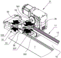
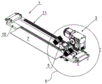
fig. 1 is a schematic perspective view of a moving assembly for a glass fiber rotary cutting machine according to an embodiment of the present invention;
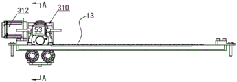
FIG. 2 is a front view of the moving assembly of the glass fiber rotary cutting machine of FIG. 1, in which the left and right brush bodies of the linked brush units are not shown;
FIG. 3 is a right side end view of the moving assembly of the glass fiber slitting mill of FIG. 1;
FIG. 4 isbase:Sub>A cross-sectional view of the moving assembly of the glass fiber rotary cutting machine of FIG. 2 along line A-A;
FIG. 5 is a perspective view of a rail mounting unit of the moving assembly of the glass fiber rotary cutting machine of FIG. 1;
FIG. 6 is an exploded perspective view of the rail mounting unit of FIG. 5 from the bottom;
FIG. 7 is a perspective view of a rolling and cutting moving unit of the moving assembly for the glass fiber rolling and cutting machine shown in FIG. 1;
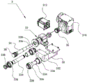
fig. 8 is an exploded perspective view of the roll-cutting movement unit shown in fig. 7;
FIG. 9 is a perspective view of a linked bristle unit of the moving assembly of the glass fiber rotary cutting machine of FIG. 1;
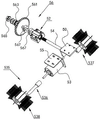
FIG. 10 is an exploded perspective view of the linked bristle unit of FIG. 9;
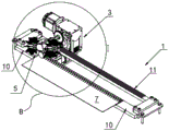
FIG. 11 is a state diagram of the moving assembly of the glass fiber rotary cutting machine of FIG. 1;
FIG. 12 is an enlarged view of part B of the moving assembly of the glass fiber rotary cutting machine of FIG. 11;
FIG. 13 is a front view of the moving assembly of the glass fiber rotary cutting machine of FIG. 11;
FIG. 14 is another view of the moving assembly of the glass fiber rotary cutting machine of FIG. 1 in use;
FIG. 15 is an enlarged view of part C of the moving assembly of the glass fiber slitting mill of FIG. 14;
fig. 16 is a front view of the moving assembly of the glass fiber rotary cutting machine of fig. 14.
Detailed Description
The following description of the embodiments of the present invention will be made with reference to the accompanying drawings.
In this document, the directions used to explain the structure and/or actions of the various parts of the disclosed embodiments, such as "left", "right", "front", "back", "up", "down", etc., are not absolute, but relative. These representations are suitable when the various parts of the disclosed embodiments are in the positions shown in the drawings, and if the position or frame of reference of the disclosed embodiments changes, they will change depending on the change in position or frame of reference of the disclosed embodiments.
As shown in fig. 1 to 4, and referring to fig. 5 to 16, the moving assembly 100 for a glass fiber rotary cutting machine according to an embodiment of the present invention includes a rail assembling unit 1, a rotary cutting moving unit 3 and a linkage brush unit 5, wherein the rotary cutting moving unit 3 is supported on the rail assembling unit 1 and is configured to be capable of moving back and forth along the rail assembling unit 1 to roll the glass fiber cloth 7, and the linkage brush unit 5 is installed on the rotary cutting moving unit 3 and is configured to be capable of moving back and forth along the rotary cutting moving unit 3 to perform a brush action.
As shown in fig. 5 and 6, and referring to fig. 1 to 4, in the present embodiment, the rail mounting unit 1 includes a table rail 10, a rack rail 11, and two connection end plates 14. As clearly shown in fig. 1 and 5, the table rail 10 and the rack rail 11 are arranged in parallel at a spacing, and are connected together at both ends by a corresponding one of the connecting end plates 14, respectively. In addition, as shown in fig. 1 and 5, the table rail 10 is provided on its top surface with a replaceable wear-resistant table liner 12, and the rack rail 11 is provided on its top surface with a rack 13. As shown in fig. 6, the longitudinal sliding grooves 16 are provided on the bottom of both the table rail 10 and the rack rail 11.
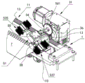
As shown in fig. 7 and 8, and referring to fig. 1 to 4, in the present embodiment, the hobbing movement unit 3 includes a connecting seat plate 30, a hobbing cutter driving mechanism 31 and a hobbing cutter bearing housing 32, a hobbing cutter shaft 34, a driving gear 36 and a hobbing cutter 38, wherein the hobbing cutter driving mechanism 31 and the hobbing cutter bearing housing 32 are mounted on the connecting seat plate 30; a hob shaft 34 is mounted on the hob bearing housing 32 and connected to the hob drive mechanism 31 so as to be driven by the hob drive mechanism 31; a drive gear 36 is fixed to the hob shaft 34 between the hob shaft bearing 32 and the hob drive mechanism 31 and meshes with the rack 13 on the rack rail 11; the hob cutter 38 is provided at the end of the hob cutter shaft 34 and is adapted to hob-cut the glass cloth 7 placed on the table rail 10. As best shown in fig. 3 and 4, the connecting seat plate 30 is located below the rack rail 11, and the roller bearing blocks 32 are located in the space 15 (see fig. 1 and 5) between the table rail 10 and the rack rail 11.
As shown in fig. 7 and 8, in the present embodiment, the hob driving mechanism 31 includes a reducer 310 attached to the connecting seat plate 30 and driving the connecting hob shaft 34, and a servo motor 312 drivingly connected to the reducer 310. The servo motor 312 can drive the roller shaft 34 to rotate anticlockwise or clockwise through the speed reducer 310, so as to drive the whole moving assembly to move left and right along the track assembly unit 1; the forward and reverse rotation of the servo motor 312 can realize the switching of the running of the roller shaft 34 in the left and right directions.
As shown in fig. 7 and 8, and referring to fig. 3 and 4, in the present embodiment, the hobbing movement unit 3 further includes a sliding support structure 33, the sliding support structure 33 includes a lower bearing seat 332 mounted on the connecting base plate 30 and supporting the hobbing bearing seat 32, a pair of support shafts 334 mounted on the lower bearing seat 332, and ball bearings 336 mounted on both ends of each support shaft 334 on both sides of the lower bearing seat 332. As shown in fig. 6, and referring to fig. 3 and 4, the longitudinal slide grooves 16 are provided on the bottoms of the table rail 10 and the rack rail 11, and two ball bearings 336 on each support shaft 334 are rollably clamped in the longitudinal slide grooves 16 of the table rail 10 and the rack rail 11, respectively. Further, in the present embodiment, as shown in fig. 8, a stopper round nut 338 is further mounted on each support shaft 334 outside each ball bearing 336 to prevent the ball bearings 336 from slipping off in the axial direction.
As shown in fig. 1, 9 and 10, in the present embodiment, the linked brush unit 5 includes a rocking switch mechanism and a brush mechanism 51. The wobble mechanism includes a motor bracket 50, an upper bearing housing 52, a wobble connecting shaft 54 and a spring damper 56. One end of the swinging connecting shaft 54 is connected with the motor bracket 50, and the upper bearing seat 52 is arranged on the roller bearing seat 32 and is used for supporting the swinging connecting shaft 54; a spring damper 56 is mounted on the other end of the swing link shaft 54 and serves to control the swing direction of the swing link shaft. The brush mechanism 51 includes a brush motor 53 mounted on the motor holder 50, and a left brush body 535 and a right brush body 537 which are drivingly connected at both sides thereof by the brush motor 53. The left and right brush bodies 535 and 537 each include a brush connecting shaft 536 connected to the brush motor 53 and a circular brush 538. In the present embodiment, the brush mechanism 51 further includes a motor base 55, and the brush motor 53 is fixedly attached to the motor holder 50 via the motor base 55.
As shown in fig. 10 and fig. 11 to 16, and referring to fig. 3, fig. 5 and fig. 9, in the present embodiment, the spring damper 56 includes a damper gear 561 and a damper butterfly spring 563, the damper gear 561 is engaged with the driving gear 36, and the damper butterfly spring 563 is sleeved between the swing connecting shaft 54 and the damper gear 561, so that when the damper gear 561 is driven by the driving gear 36 to rotate counterclockwise, the swing connecting shaft 54 is in a first swing position, at which the left brush 535 is in a low position operating state, and the right brush 537 is in a high position raised state, as shown in fig. 11 to fig. 13; when the damper gear 561 is driven by the driving gear 36 to rotate clockwise, the swing connecting shaft 54 is at the second swing position, and at this time, the left brush 535 is at the high-position lifted state, and the right brush 537 is at the low-position working state.
It should be noted that, in the present embodiment, the damper butterfly spring 563 is provided to transmit the reverse force or the forward force applied by the damper gear 561 to the swinging connecting shaft 54, so that the swinging connecting shaft 54 drives the brush motor 53 mounted thereon to swing left or right via the motor bracket 50, so as to press the left brush body 535 into the low position operating state or press the right brush body 537 into the low position operating state. In addition, as shown in fig. 10, in the present embodiment, the spring damper 56 further includes a damper nut 565, and the damper nut 565 is attached to the other end of the rocking connecting shaft 54 outside the damper gear 561. Further, a band 567 for positioning the upper bearing housing 52 and the spring damper 56 is provided on the rocking connecting shaft 54.
Referring to fig. 11 to 16, the working process of the moving assembly for a glass fiber hobbing machine of the present invention is briefly described:
as shown in fig. 11 to 13, when the servo motor 312 is started and rotates forward, the servo motor 312 drives the roller shaft 34 to rotate clockwise via the speed reducer 310, and at this time, the pinion gear 36 is driven by the roller shaft 34 to rotate clockwise and simultaneously travels rightward along the rack rail 11 by meshing with the rack 13 on the rack rail 11;
in the process, the hob cutter 38 rolls and cuts (chamfers) the glass fiber cloth 7 on the workbench track 10 while moving rightwards along the workbench track 10, namely, the rolling and cloth cutting of the glass fiber cloth 7 are realized;
when the driving gear 36 rotates clockwise and moves rightwards along the rack rail 11 simultaneously, the damper gear 561 rotates anticlockwise under the stirring of the driving gear 36, the counterclockwise rotating force is transmitted to the swinging connecting shaft 54 through the damper butterfly spring 563, the swinging connecting shaft 54 drives the motor support 50 and the brush mechanism 51 thereon to rotate to the first swinging position, the left brush body 535 is pressed downwards all the time, and the right brush body 537 is lifted, that is: in this position, the left brush 535 of the brushing mechanism 51 is in a low position working state, and the right brush 537 is in a high position lifting state, in this state, as the hob 38 advances to the right in front to cut the glass fiber cloth 7, the left brush 535 follows the roller 38 to comb the cut glass fiber at the back;
as shown in fig. 14 to 16, when the servo motor 312 is reversed, the servo motor 312 drives the roller shaft 34 via the speed reducer 310 to rotate counterclockwise, and at this time, the pinion gear 36 also rotates counterclockwise by being driven by the roller shaft 34 and simultaneously travels leftward along the rack rail 11 by means of engagement with the rack 13 on the rack rail 11;
in the process, the hob cutter 38 rolls and cuts (chamfers) the glass fiber cloth 7 on the workbench track 10 while moving leftwards along the workbench track 10, so that the rolling and cloth cutting of the glass fiber cloth 7 are realized;
when the driving gear 36 rotates counterclockwise and moves leftward along the rack rail 11, the damper gear 561 rotates clockwise under the shifting of the driving gear 36, the clockwise rotation force is transmitted to the swing connecting shaft 54 via the damper butterfly spring 563, the swing connecting shaft 54 drives the motor support 50 and the brush mechanism 51 thereon to rotate to the second swing position, and the right brush body 537 is pressed down all the time to lift the left brush body 535, that is: in this position, the right brush body 537 of the brush mechanism 51 is in the low position operating state and the left brush body 535 is in the high position raised state, and in this state, the right brush body 537 combs the cut glass fiber along with the movement of the hob cutter 38 to the left to cut the glass fiber cloth 7.
While the invention has been described with reference to the above embodiments, it will be understood by those skilled in the art that various changes and modifications may be made to the above-described arrangements, including combinations of features disclosed herein either individually or in any combination as is evident from the below disclosure. These variants and/or combinations fall within the technical field of the present invention and are intended to be protected by the following claims.
Claims (10)
1. The utility model provides a fine hobbing machine of glass moves subassembly which characterized in that includes:
the rail assembly unit comprises a workbench rail and a rack rail which are arranged in parallel at intervals, and two connecting end plates which are respectively connected with the workbench rail and the rack rail at two ends;
the hobbing movement unit comprises a connecting base plate, a hobbing cutter driving mechanism and a hobbing cutter bearing seat which are arranged on the connecting base plate, a hobbing cutter shaft which is arranged on the hobbing cutter bearing seat and connected with the hobbing cutter driving mechanism, a driving gear which is fixed on the hobbing cutter shaft between the hobbing cutter shaft bearing seat and the hobbing cutter driving mechanism and is meshed with the rack rail, and a hobbing cutter which is arranged at the tail end of the hobbing cutter shaft and is suitable for hobbing glass fiber cloth arranged on the workbench rail, wherein the connecting base plate is positioned below the rack rail, and the hobbing cutter bearing seat is positioned between the workbench rail and the rack rail.
2. The moving assembly for glass fiber hobbing machine according to claim 1, wherein the hobbing moving unit further comprises a sliding support structure, the sliding support structure comprises a lower bearing seat mounted on the connecting seat plate and used for supporting the hobbing bearing seat, a pair of support shafts mounted on the lower bearing seat, ball bearings respectively mounted on two ends of each support shaft on two sides of the lower bearing seat, and longitudinal sliding grooves are arranged on the bottoms of the worktable rail and the rack rail, and the two ball bearings on each support shaft are respectively and rollably clamped in the longitudinal sliding grooves of the worktable rail and the rack rail.
3. The moving assembly of claim 2, wherein a stop round nut is further mounted on each support shaft outside each ball bearing.
4. The moving assembly of claim 3 wherein the hob driving mechanism comprises a reducer mounted on the connecting base plate and drivingly connected to the hob shaft, and a servo motor drivingly connected to the reducer.
5. The moving assembly for a glass fiber rotary cutting machine according to claim 4, wherein the servo motor is arranged to rotate in a forward and reverse direction so as to drive the roller shaft to rotate clockwise or counterclockwise via the reducer, and when the roller shaft rotates clockwise, the driving gear is driven by the roller shaft to rotate clockwise and simultaneously travel rightward along the rack rail by means of engagement with the rack rail; when the hob shaft rotates anticlockwise, the driving gear rotates anticlockwise under the driving of the hob shaft and moves leftwards along the rack rail by means of meshing with the rack rail.
6. The moving assembly of any one of claims 1 to 5, further comprising a linked brushing unit, the linked brushing unit comprising:
the rocking reversing mechanism comprises a motor bracket, a rocking connecting shaft, an upper bearing seat and a spring damper, wherein one end of the rocking connecting shaft is connected with the motor bracket, the upper bearing seat is arranged on the hob bearing seat and used for supporting the rocking connecting shaft, and the spring damper is arranged at the other end of the rocking connecting shaft and used for controlling the rocking direction of the rocking connecting shaft;
the brushing mechanism comprises a brush motor arranged on the motor support, a left brush body and a right brush body which are in driving connection with the brush motor at two sides of the brush motor;
the spring damper comprises a damper gear and a damper butterfly spring, the damper gear is meshed with the driving gear, and the damper butterfly spring is sleeved between the swinging connecting shaft and the damper gear, so that when the damper gear rotates anticlockwise under the driving of the driving gear, the swinging connecting shaft is in a first swinging position, at the moment, the left hairbrush body is in a low-position working state, and the right hairbrush body is in a high-position lifting state; when the damper gear is driven by the driving gear to rotate clockwise, the swinging connecting shaft is located at a second swinging position, at the moment, the left hairbrush body is in a high-position lifting state, and the right hairbrush body is in a low-position working state.
7. The moving assembly for a glass fiber rotary cutting machine according to claim 6, wherein said spring damper further comprises a damper nut mounted on said other end of said rocking connecting shaft outside of the damper gear.
8. The moving assembly of claim 7, wherein a clamp for positioning the upper bearing block and the spring damper is further provided on the rocking link shaft.
9. The moving assembly for a glass fiber slitting roller of claim 8, wherein the left brush body and the right brush body each comprise a brush connecting shaft and a round brush connected to the brush motor.
10. The moving assembly for glass fiber rotary cutting machine according to any one of claims 1 to 5, wherein the top surface of the workbench track is further provided with a replaceable wear-resistant workbench lining plate.
Priority Applications (1)
| Application Number | Priority Date | Filing Date | Title |
|---|---|---|---|
| CN202222235177.2U CN218453022U (en) | 2022-08-24 | 2022-08-24 | Moving assembly for glass fiber rotary cutting machine |
Applications Claiming Priority (1)
| Application Number | Priority Date | Filing Date | Title |
|---|---|---|---|
| CN202222235177.2U CN218453022U (en) | 2022-08-24 | 2022-08-24 | Moving assembly for glass fiber rotary cutting machine |
Publications (1)
| Publication Number | Publication Date |
|---|---|
| CN218453022U true CN218453022U (en) | 2023-02-07 |
Family
ID=85124254
Family Applications (1)
| Application Number | Title | Priority Date | Filing Date |
|---|---|---|---|
| CN202222235177.2U Active CN218453022U (en) | 2022-08-24 | 2022-08-24 | Moving assembly for glass fiber rotary cutting machine |
Country Status (1)
| Country | Link |
|---|---|
| CN (1) | CN218453022U (en) |
Cited By (1)
| Publication number | Priority date | Publication date | Assignee | Title |
|---|---|---|---|---|
| CN115401736A (en) * | 2022-08-24 | 2022-11-29 | 苏州复玖机械科技有限公司 | Moving assembly for glass fiber rotary cutting machine |
-
2022
- 2022-08-24 CN CN202222235177.2U patent/CN218453022U/en active Active
Cited By (1)
| Publication number | Priority date | Publication date | Assignee | Title |
|---|---|---|---|---|
| CN115401736A (en) * | 2022-08-24 | 2022-11-29 | 苏州复玖机械科技有限公司 | Moving assembly for glass fiber rotary cutting machine |
Similar Documents
| Publication | Publication Date | Title |
|---|---|---|
| CN111618965B (en) | Special delimbing tool for bamboo processing and using method thereof | |
| CN201553487U (en) | An electric nickel automatic alignment machine | |
| CN211332477U (en) | Mechanism for polishing inner ring and outer ring of bearing | |
| CN218059670U (en) | Automatic glass fiber slitting mill | |
| CN107639487B (en) | Stone polishing machine | |
| CN212581110U (en) | A feeding device for a cutting machine | |
| CN201189612Y (en) | Double driving apparatus for numerically controlling beam motion of planer-type milling machine | |
| CN115870690B (en) | Grille slag remover | |
| CN210406310U (en) | Spherical nursery stock trimming knife rest and trimmer | |
| CN116117218A (en) | High-precision metal product plate shearing mechanism and use method thereof | |
| CN107751278B (en) | Horizontal dough rolling device | |
| CN215236953U (en) | Supporting platform device of up-moving type five metals bender | |
| CN208234070U (en) | A kind of loading and unloading robot | |
| CN111633837B (en) | A floor cutting device | |
| CN115401736A (en) | Moving assembly for glass fiber rotary cutting machine | |
| CN214519307U (en) | Automatic edge grinding machine for stone | |
| CN211103346U (en) | Automatic polishing assembly line for steel plate | |
| CN215881773U (en) | Full-automatic guillootine | |
| CN106423940A (en) | Cleaning and pressing device for silver belt trimming device | |
| CN205133402U (en) | Full -automatic multi -functional glass -cutting machine | |
| CN208151746U (en) | A kind of Cloth Cutting device | |
| CN115573160A (en) | Automatic glass fiber roller cutting machine | |
| CN220744584U (en) | Glass conveying mechanism and glass cleaning device | |
| CN221271621U (en) | Large stone saw for cutting stone carving waste | |
| CN114210794A (en) | Rolling forming machine |
Legal Events
| Date | Code | Title | Description |
|---|---|---|---|
| GR01 | Patent grant | ||
| GR01 | Patent grant |