CN218444259U - Capacitance type air pressure sensor - Google Patents
Capacitance type air pressure sensor Download PDFInfo
- Publication number
- CN218444259U CN218444259U CN202222769089.0U CN202222769089U CN218444259U CN 218444259 U CN218444259 U CN 218444259U CN 202222769089 U CN202222769089 U CN 202222769089U CN 218444259 U CN218444259 U CN 218444259U
- Authority
- CN
- China
- Prior art keywords
- pressure sensor
- air pressure
- groove
- main body
- installation
- Prior art date
- Legal status (The legal status is an assumption and is not a legal conclusion. Google has not performed a legal analysis and makes no representation as to the accuracy of the status listed.)
- Expired - Fee Related
Links
Images


Landscapes
- Measuring Fluid Pressure (AREA)
Abstract
本实用新型属于气压传感器技术领域,且公开了电容式气压传感器,包括气压传感器主体,所述气压传感器主体的前端面设有测头,所述气压传感器主体的端面连接有导线,所述气压传感器主体的底端设有安装组件,本实用新型通过设置安装组件、固定组件和连接组件等,在对气压传感器主体将安装时,通过设于气压传感器底部的安装组件和固定组件可将其牢靠的安装在设备内,防止气压传感器主体在设备内产生松动,此外,在需要对气压传感器主体进行拆卸检修时,无需将安装组件和固定组件从设备内拆卸,通过设置在气压传感器主体和安装组件之间的连接组件,可将气压传感器主体和安装组件分离,方便后续对气压传感器主体进行检修和更换。
The utility model belongs to the technical field of air pressure sensors, and discloses a capacitive air pressure sensor, which comprises an air pressure sensor main body. The bottom end of the main body is provided with a mounting component. The utility model sets the mounting component, the fixing component and the connecting component, etc., and when the main body of the air pressure sensor is to be installed, the mounting component and the fixing component at the bottom of the air pressure sensor can securely fasten it. Installed in the equipment to prevent the main body of the air pressure sensor from loosening in the equipment. In addition, when the main body of the air pressure sensor needs to be disassembled and overhauled, there is no need to disassemble the installation component and the fixing component from the equipment. The connection components between the air pressure sensor body and the installation assembly can be separated to facilitate subsequent maintenance and replacement of the air pressure sensor body.
Description
技术领域technical field
本实用新型属于气压传感器技术领域,具体涉及电容式气压传感器。The utility model belongs to the technical field of air pressure sensors, in particular to a capacitive air pressure sensor.
背景技术Background technique
电容式压力传感器,是一种利用电容敏感元件将被测压力转换成与之成一定关系的电量输出的压力传感器,广泛的应用在智能手机、智能音箱等电子设备内,现有的气压传感器在安装时,通常是通过胶带将其固定在线路板上,这种方法不便于后续拆卸压力传感器进行检修和更换,以及对压力传感器固定的不够牢靠,此外,现有的气压传感器连接的导线处为设置密封结构,灰尘易从导线连接处进入气压传感器内部,长时间容易影响其正常使用,以及导线连接处容易在气压传感器震动的情况下摆动,容易和气压传感器接触不良等情况发生。A capacitive pressure sensor is a pressure sensor that uses a capacitive sensitive element to convert the measured pressure into an electrical output that has a certain relationship with it. It is widely used in electronic devices such as smart phones and smart speakers. During installation, it is usually fixed on the circuit board by adhesive tape. This method is not convenient for subsequent disassembly of the pressure sensor for maintenance and replacement, and the pressure sensor is not fixed enough. In addition, the wires connected to the existing air pressure sensor are With a sealed structure, dust can easily enter the air pressure sensor from the wire connection, which will easily affect its normal use for a long time, and the wire connection is easy to swing when the air pressure sensor vibrates, and it is easy to have poor contact with the air pressure sensor.
实用新型内容Utility model content
本实用新型的目的在于提供电容式气压传感器,以解决上述背景技术中提出的现有的气压传感器安装拆卸不便以及灰尘易从导线连接处进入气压传感器内部和未对与气压传感器导线连接处的导线进行保护的问题。The purpose of this utility model is to provide a capacitive air pressure sensor to solve the inconvenience of installation and disassembly of the existing air pressure sensor proposed in the above-mentioned background technology and the fact that dust easily enters the interior of the air pressure sensor from the wire connection and the wires at the wire connection of the air pressure sensor are not aligned. problem of protection.
为实现上述目的,本实用新型提供如下技术方案:电容式气压传感器,包括:In order to achieve the above object, the utility model provides the following technical solutions: a capacitive air pressure sensor, comprising:
气压传感器主体,所述气压传感器主体的前端面设有测头,所述气压传感器主体的端面连接有导线,所述气压传感器主体的底端设有安装组件。The main body of the air pressure sensor, the front end of the main body of the air pressure sensor is provided with a measuring head, the end surface of the main body of the air pressure sensor is connected with a wire, and the bottom of the main body of the air pressure sensor is provided with a mounting assembly.
优选的,所述安装组件包括安装板和安装槽,所述安装板设于气压传感器主体的底端,所述安装槽开设在安装板的顶端,所述气压传感器主体的底端嵌至安装槽内,所述安装板的两侧设有固定组件。Preferably, the mounting assembly includes a mounting plate and a mounting groove, the mounting plate is arranged at the bottom end of the main body of the air pressure sensor, the mounting groove is opened at the top of the mounting plate, and the bottom end of the air pressure sensor body is embedded in the mounting groove Inside, the two sides of the mounting plate are provided with fixing components.
优选的,所述固定组件包括固定板、螺纹槽和螺纹杆,所述固定板安装在安装板的两侧,所述螺纹槽开设在固定板的顶端,所述螺纹槽旋合连接在螺纹槽内,所述安装板与气压传感器主体之间设有连接组件。Preferably, the fixing assembly includes a fixing plate, a threaded groove and a threaded rod, the fixing plate is installed on both sides of the mounting plate, the threaded groove is opened on the top of the fixing plate, and the threaded groove is screwed and connected to the threaded groove Inside, a connecting component is provided between the mounting plate and the main body of the air pressure sensor.
优选的,所述连接组件包括连接块和连接槽,所述连接槽开设在安装板的顶端四侧,所述连接槽位于安装槽的下方,所述连接块安装在气压传感器主体的底端四侧,所述连接块嵌至连接槽内。Preferably, the connection assembly includes a connection block and a connection groove, the connection groove is set on four sides of the top end of the installation plate, the connection groove is located below the installation groove, and the connection block is installed on the bottom four sides of the main body of the air pressure sensor. On the side, the connection block is embedded in the connection groove.
优选的,所述导线的外部套设有套环,所述套环的一端与气压传感器主体后端面相连,所述套环与气压传感器主体之间设有插接组件。Preferably, a collar is sheathed on the outside of the wire, one end of the collar is connected to the rear end surface of the main body of the air pressure sensor, and a plug-in assembly is provided between the collar and the main body of the air pressure sensor.
优选的,所述插接组件包括嵌槽和嵌块,所述嵌槽开设在套环靠近气压传感器主体的一端面上,所述嵌块安装在气压传感器主体且位于导线连接口的两端上,所述嵌块嵌至嵌槽内。Preferably, the plug-in assembly includes a socket and an inlay, the socket is opened on an end surface of the collar close to the main body of the air pressure sensor, and the inlay is installed on the main body of the air pressure sensor and is located at both ends of the wire connection port , the slug is embedded in the slot.
与现有技术相比,本实用新型的有益效果是:Compared with the prior art, the beneficial effects of the utility model are:
(1)本实用新型通过设置安装组件、固定组件和连接组件等,在对气压传感器主体将安装时,通过设于气压传感器底部的安装组件和固定组件可将其牢靠的安装在设备内,防止气压传感器主体在设备内产生松动,此外,在需要对气压传感器主体进行拆卸检修时,无需将安装组件和固定组件从设备内拆卸,通过设置在气压传感器主体和安装组件之间的连接组件,可将气压传感器主体和安装组件分离,方便后续对气压传感器主体进行检修和更换。(1) The utility model is provided with installation components, fixing components and connecting components, etc., when the main body of the air pressure sensor is installed, it can be firmly installed in the equipment through the installation components and fixing components at the bottom of the air pressure sensor, preventing The main body of the air pressure sensor is loose in the equipment. In addition, when the main body of the air pressure sensor needs to be disassembled and overhauled, it is not necessary to disassemble the installation component and the fixed component from the equipment. The main body of the air pressure sensor is separated from the installation component, which facilitates subsequent maintenance and replacement of the main body of the air pressure sensor.
(2)本实用新型通过设置套环、嵌槽和嵌块等,通过设置在气压传感器主体与导线连接处的套环,可防止灰尘进入气压传感器主体内,进而使气压传感器主体能够正常的工作,其中,套环可有效的保护与气压传感器主体连接处的导线,防止其产生较大的摆动,进而避免导线与气压传感器主体接触不良或氧化等情况发生,此外,套环通过嵌块和嵌槽连接,方便后续在更换导线时进行拆卸。(2) The utility model can prevent dust from entering the main body of the air pressure sensor by setting the collar, embedded groove and insert, etc., through the collar at the connection between the main body of the air pressure sensor and the wire, so that the main body of the air pressure sensor can work normally , wherein the collar can effectively protect the wire at the connection with the main body of the air pressure sensor and prevent it from swinging greatly, thereby avoiding poor contact or oxidation between the wire and the main body of the air pressure sensor. In addition, the collar passes through the insert and the insert Groove connection to facilitate subsequent disassembly when replacing wires.
附图说明Description of drawings
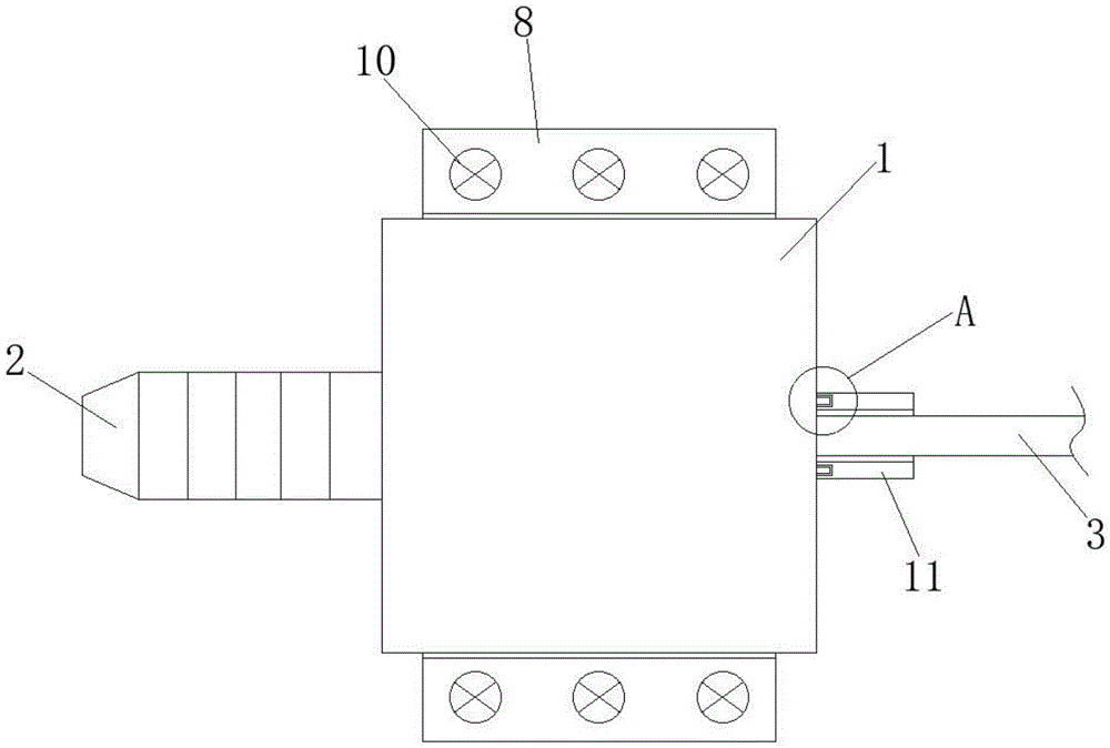
图1为本实用新型的结构示意图;Fig. 1 is the structural representation of the utility model;
图2为本实用新型的安装组件的结构示意图;Fig. 2 is the structural representation of the mounting assembly of the present utility model;
图3为图1中的A处放大图;Figure 3 is an enlarged view of A in Figure 1;
图中:1、气压传感器主体;2、测头;3、导线;4、安装板;5、安装槽;6、连接槽;7、连接块;8、固定板;9、螺纹槽;10、螺纹杆;11、套环;12、嵌槽;13、嵌块。In the figure: 1. The main body of the air pressure sensor; 2. The measuring head; 3. The wire; 4. The mounting plate; 5. The mounting groove; 6. The connecting groove; 7. The connecting block; 8. The fixing plate; Threaded rod; 11, collar; 12, embedded groove; 13, embedded block.
具体实施方式Detailed ways
下面将结合本实用新型实施例中的附图,对本实用新型实施例中的技术方案进行清楚、完整地描述,显然,所描述的实施例仅仅是本实用新型一部分实施例,而不是全部的实施例。基于本实用新型中的实施例,本领域普通技术人员在没有做出创造性劳动前提下所获得的所有其他实施例,都属于本实用新型保护的范围。The technical solutions in the embodiments of the present invention will be clearly and completely described below in conjunction with the accompanying drawings in the embodiments of the present invention. Obviously, the described embodiments are only part of the embodiments of the present invention, not all of them. example. Based on the embodiments of the present utility model, all other embodiments obtained by persons of ordinary skill in the art without making creative efforts belong to the scope of protection of the present utility model.
请参阅图1-图3所示,本实用新型提供如下技术方案:电容式气压传感器,包括:Please refer to Fig. 1-shown in Fig. 3, the utility model provides following technical scheme: capacitive air pressure sensor, comprises:
气压传感器主体1,气压传感器主体1的前端面设有测头2,气压传感器主体1的端面连接有导线3,气压传感器主体1的底端设有安装组件。The main body of the
请参阅图1-图2所示,安装组件包括安装板4和安装槽5,安装板4设于气压传感器主体1的底端,安装槽5开设在安装板4的顶端,气压传感器主体1的底端嵌至安装槽5内,安装板4的两侧设有固定组件。Please refer to Fig. 1-shown in Fig. 2, the mounting assembly includes a
固定组件包括固定板8、螺纹槽9和螺纹杆10,固定板8安装在安装板4的两侧,螺纹槽9开设在固定板8的顶端,螺纹槽9旋合连接在螺纹槽9内,安装板4与气压传感器主体1之间设有连接组件。The fixed assembly includes a
连接组件包括连接块7和连接槽6,连接槽6开设在安装板4的顶端四侧,连接槽6位于安装槽5的下方,连接块7安装在气压传感器主体1的底端四侧,连接块7嵌至连接槽6内。The connection assembly includes a
通过上述技术方案:在对气压传感器主体1进行安装时,先将安装板4放置在设备的安装座上,随后将螺纹杆10通过螺纹槽9将其固定在设备的安装座上,可将气压传感器主体1固定牢靠,安装较为简便,防止气压传感器主体1在设备内产生松动,此外,在需要将气压传感器主体1拆卸进行检修时,无需将安装板4进行拆卸,通过将气压传感器主体1底部安装的连接块7移出连接槽6即可将其从安装板4上拆卸,方便后续对气压传感器主体1进行检修和更换。Through the above technical solution: when installing the
请参阅图1和图3所示,导线3的外部套设有套环11,套环11的一端与气压传感器主体1后端面相连,套环11与气压传感器主体1之间设有插接组件,插接组件包括嵌槽12和嵌块13,嵌槽12开设在套环11靠近气压传感器主体1的一端面上,嵌块13安装在气压传感器主体1且位于导线3连接口的两端上,嵌块13嵌至嵌槽12内。Please refer to Fig. 1 and Fig. 3, a
通过上述技术方案:在气压传感器主体1的使用过程中,设置在导线3与气压传感器主体1连接处的套环11可对其进行密封,防止灰尘进入气压传感器主体1内部,避免影响气压传感器主体1的使用,其中,设置的套环11可有效的保护与气压传感器主体1连接处的导线3,防止其产生较大的摆动,进而避免导线3与气压传感器主体1接触不良或氧化等情况发生,此外,在需要更换导线3时,可将嵌块13移出嵌槽12,方便后续将套环11从气压传感器主体1上卸下。Through the above technical solution: during the use of the air pressure sensor
尽管已经示出和描述了本实用新型的实施例,对于本领域的普通技术人员而言,可以理解在不脱离本实用新型的原理和精神的情况下可以对这些实施例进行多种变化、修改、替换和变型,本实用新型的范围由所附权利要求及其等同物限定。Although the embodiments of the present invention have been shown and described, those skilled in the art can understand that various changes and modifications can be made to these embodiments without departing from the principle and spirit of the present invention , replacements and modifications, the scope of the present utility model is defined by the appended claims and their equivalents.
Claims (6)
Priority Applications (1)
| Application Number | Priority Date | Filing Date | Title |
|---|---|---|---|
| CN202222769089.0U CN218444259U (en) | 2022-10-20 | 2022-10-20 | Capacitance type air pressure sensor |
Applications Claiming Priority (1)
| Application Number | Priority Date | Filing Date | Title |
|---|---|---|---|
| CN202222769089.0U CN218444259U (en) | 2022-10-20 | 2022-10-20 | Capacitance type air pressure sensor |
Publications (1)
| Publication Number | Publication Date |
|---|---|
| CN218444259U true CN218444259U (en) | 2023-02-03 |
Family
ID=85068593
Family Applications (1)
| Application Number | Title | Priority Date | Filing Date |
|---|---|---|---|
| CN202222769089.0U Expired - Fee Related CN218444259U (en) | 2022-10-20 | 2022-10-20 | Capacitance type air pressure sensor |
Country Status (1)
| Country | Link |
|---|---|
| CN (1) | CN218444259U (en) |
-
2022
- 2022-10-20 CN CN202222769089.0U patent/CN218444259U/en not_active Expired - Fee Related
Similar Documents
| Publication | Publication Date | Title |
|---|---|---|
| CN201145752Y (en) | Fiber Connector | |
| CN205355374U (en) | Intelligent recognition's integrated interface of telescopic computer network | |
| CN207283751U (en) | A kind of microphone with antistatic protection function | |
| CN202679629U (en) | MEMS (Micro-electromechanical System) microphone | |
| CN105514740B (en) | Bass boost conversion head and bass boost method | |
| CN218916661U (en) | Pressure sensor | |
| CN207677970U (en) | Modularization casing and audio amplifier suitable for audio amplifier uses | |
| CN216214587U (en) | Electronic distribution frame with contact induction function | |
| CN206640902U (en) | The shell structure and electronic product of a kind of built-in microphone | |
| CN211858012U (en) | An LED display with integrated touch and display | |
| CN210053582U (en) | Sound code receiver of access & exit device | |
| CN211126285U (en) | A drop-proof connector | |
| CN219301664U (en) | A new packaging device for optical fiber sensor | |
| CN209728249U (en) | A low-cost optical device | |
| CN202066853U (en) | Point type combustible gas detector based on multiple communication modes | |
| CN217904745U (en) | Induction sensor | |
| CN218330397U (en) | Dual channel fiber optic pressure sensor | |
| CN208353605U (en) | A kind of acoustic sensor and micro-electro-mechanical microphone packaging structure | |
| CN206195956U (en) | Explosion -proof video detecting device | |
| CN217216680U (en) | Small-size strip industry camera | |
| CN222826012U (en) | A waterproof electronic waybill with replaceable sensor | |
| CN103644984A (en) | Miniature pressure sensor | |
| CN223053163U (en) | EMC filtering PCB board | |
| CN215679211U (en) | A kind of electronic computer shell with moisture-proof structure | |
| CN217465909U (en) | A simple liquid level sensor |
Legal Events
| Date | Code | Title | Description |
|---|---|---|---|
| GR01 | Patent grant | ||
| GR01 | Patent grant | ||
| CF01 | Termination of patent right due to non-payment of annual fee |
Granted publication date: 20230203 |
|
| CF01 | Termination of patent right due to non-payment of annual fee |