CN218438556U - Corrugated steel plate coupling beam damper - Google Patents
Corrugated steel plate coupling beam damper Download PDFInfo
- Publication number
- CN218438556U CN218438556U CN202223439754.6U CN202223439754U CN218438556U CN 218438556 U CN218438556 U CN 218438556U CN 202223439754 U CN202223439754 U CN 202223439754U CN 218438556 U CN218438556 U CN 218438556U
- Authority
- CN
- China
- Prior art keywords
- plate
- corrugated steel
- steel plate
- end plate
- damper
- Prior art date
- Legal status (The legal status is an assumption and is not a legal conclusion. Google has not performed a legal analysis and makes no representation as to the accuracy of the status listed.)
- Active
Links
Images




Landscapes
- Buildings Adapted To Withstand Abnormal External Influences (AREA)
Abstract
本实用新型公开了一种波纹钢板连梁阻尼器,包括:第一端板、第二端板、波纹钢板、第一盖板和第二盖板,第一端板和第二端板相对设置;波纹钢板固定连接地设于第一端板和第二端板之间;第一盖板和第二盖板相对设置,第一盖板固定连接地设于波纹钢板的底部,第二盖板固定连接地设于波纹钢板的顶部。根据本实用新型实施例的波纹钢板连梁阻尼器,针对一般的金属剪切型阻尼器容易发生局部屈曲的问题,通过改进装置核心部分的金属材料形状构造实现防屈曲,使用波纹钢板代替一般的平面金属构造可显著改善连梁的剪切屈服特征。连梁阻尼器体积较小,可以在不影响建筑使用功能的基础上进行灵活的布置。阻尼器安装简便,受到损坏后容易更换,修复方便。
The utility model discloses a corrugated steel plate coupling beam damper, comprising: a first end plate, a second end plate, a corrugated steel plate, a first cover plate and a second cover plate, the first end plate and the second end plate are arranged oppositely The corrugated steel plate is fixedly connected between the first end plate and the second end plate; the first cover plate and the second cover plate are arranged oppositely, the first cover plate is fixedly connected to the bottom of the corrugated steel plate, and the second cover plate It is fixedly connected to the top of the corrugated steel plate. According to the corrugated steel plate coupling beam damper according to the embodiment of the utility model, aiming at the problem that the general metal shear type damper is prone to local buckling, the buckling resistance is realized by improving the metal material shape structure of the core part of the device, and the corrugated steel plate is used instead of the general The planar metal construction can significantly improve the shear yield characteristics of the coupling beam. The coupling beam damper is small in size and can be flexibly arranged on the basis of not affecting the function of the building. The damper is easy to install, easy to replace when damaged, and easy to repair.
Description
技术领域technical field
本实用新型涉及建筑工程消能减震技术领域,具体而言,涉及一种波纹钢板连梁阻尼器。The utility model relates to the technical field of energy dissipation and shock absorption in construction engineering, in particular to a corrugated steel plate coupling beam damper.
背景技术Background technique
随着我国建筑行业的飞速发展,城市中建筑密度增大和结构层数增高,传统的抗震结构难以满足现代建筑的使用要求。为了满足结构侧向变形的需求,钢筋混凝土剪力墙结构无疑成为首选的结构形式。连梁作为连接两片墙肢的主要耗能构件,起到了十分重要的作用,是剪力墙体系中的第一道防线。在地震作用下,连梁先于墙肢发生墙肢发生屈服并发生塑性变形以耗散地震能量,从而起到保护墙肢的作用,由于实际工程中的跨高比较大,其破坏模式以脆性的剪切破坏为主。With the rapid development of my country's construction industry, the density of buildings and the number of layers of structures in cities have increased, and traditional anti-seismic structures are difficult to meet the requirements of modern buildings. In order to meet the needs of the lateral deformation of the structure, the reinforced concrete shear wall structure has undoubtedly become the preferred structural form. As the main energy-dissipating component connecting two wall piers, the coupling beam plays a very important role and is the first line of defense in the shear wall system. Under the action of an earthquake, the coupling beams yield before the wall pier and undergo plastic deformation to dissipate the seismic energy, thereby protecting the wall pier. Due to the relatively large span height in actual engineering, its failure mode is brittle The shear failure is dominant.
近些年来的研究表明消能减震技术可以有效的改善结构中构件的损伤程度,通过在结构中增添消能减震装置来减小主体结构的地震反应。目前应用于实际工程和研究的阻尼器种类很多,大体上可分为速度相关型和位移相关型两大类,其中速度相关型阻尼器通过阻尼材料和与速度相关和的工作机制为结构提供阻尼效应来减小结构的地震反应。位移相关型阻尼器通过自身材料的塑性变形发生滞回变形耗能来消散地震能量。Studies in recent years have shown that energy dissipation and shock absorption technology can effectively improve the damage degree of components in the structure, and reduce the seismic response of the main structure by adding energy dissipation and shock absorption devices to the structure. At present, there are many kinds of dampers used in practical engineering and research, which can be roughly divided into two categories: speed-related and displacement-related. Among them, the speed-related damper provides damping for the structure through the damping material and the working mechanism related to the speed. effect to reduce the seismic response of the structure. The displacement-dependent damper dissipates the seismic energy through the hysteretic deformation of the plastic deformation of its own material to dissipate energy.
结合连梁的受力特点,与连梁相关的阻尼器又可分为粘滞阻尼器、粘弹性阻尼器、摩擦阻尼器、软钢阻尼器和形状记忆合金阻尼器等多种阻尼器,通过这些新型的构造方式提高连梁的延性和耗能能力,有效地防止连梁发生脆性的剪切破坏。Combined with the force characteristics of the coupling beam, the dampers related to the coupling beam can be divided into viscous dampers, viscoelastic dampers, friction dampers, mild steel dampers and shape memory alloy dampers. These new construction methods improve the ductility and energy dissipation capacity of the coupling beam, and effectively prevent the brittle shear failure of the coupling beam.
相关技术中,连梁阻尼器采用增添加劲肋的方式来防止核心耗能部分发生屈曲,但是存在钢材用量较大,材料利用率较低。另外,普通连梁耗能效果有限,当超过其自身耗能范围,会使阻尼器损伤较为严重,修复困难;因此,存在改进空间。In related technologies, stiffening ribs are added to the coupling beam damper to prevent buckling of the core energy-dissipating part, but there is a large amount of steel used and a low material utilization rate. In addition, the energy dissipation effect of ordinary coupling beams is limited, and when the energy dissipation range exceeds its own energy consumption range, the damper will be seriously damaged and repaired difficult; therefore, there is room for improvement.
发明内容Contents of the invention
为达到上述目的,本实用新型提出一种波纹钢板连梁阻尼器,具有良好的防屈曲性能,耗能能力增强,力学性能稳定且承载力更高。安装简便,受到损坏后容易更换,修复方便,经济性更好。In order to achieve the above purpose, the utility model proposes a corrugated steel plate coupling beam damper, which has good anti-buckling performance, enhanced energy dissipation capacity, stable mechanical properties and higher bearing capacity. Easy to install, easy to replace after being damaged, easy to repair, and better economical.
本实用新型提出一种波纹钢板连梁阻尼器,包括:第一端板,第二端板,所述第一端板和所述第二端板相对设置;波纹钢板,所述波纹钢板固定连接地设于所述第一端板和所述第二端板之间;第一盖板,所述第一盖板固定连接地设于所述波纹钢板的底部,并且其两端分别与所述第一端板和所述第二端板固定连接;第二盖板,所述第二盖板固定连接地设于所述波纹钢板的顶部,并且其两端分别与所述第一端板和所述第二端板固定连接。The utility model proposes a corrugated steel plate connecting beam damper, comprising: a first end plate, a second end plate, the first end plate and the second end plate are arranged oppositely; a corrugated steel plate, the corrugated steel plate is fixedly connected ground between the first end plate and the second end plate; a first cover plate, the first cover plate is fixedly connected to the bottom of the corrugated steel plate, and its two ends are respectively connected to the The first end plate is fixedly connected to the second end plate; the second cover plate is fixedly connected to the top of the corrugated steel plate, and its two ends are respectively connected to the first end plate and the second end plate. The second end plate is fixedly connected.
根据本实用新型实施例的波纹钢板连梁阻尼器,所述波纹钢板上具有多个连续的向内凹陷或者向外凸出的梯形波纹。According to the corrugated steel plate coupling beam damper of the embodiment of the present invention, the corrugated steel plate has a plurality of continuous trapezoidal corrugations that are concave inward or protruding outward.
根据本实用新型实施例的波纹钢板连梁阻尼器,所述梯形波纹沿所述波纹钢板的纵向延伸。According to the corrugated steel plate coupling beam damper of the embodiment of the present invention, the trapezoidal corrugations extend along the longitudinal direction of the corrugated steel plate.
根据本实用新型实施例的波纹钢板连梁阻尼器,所述梯形波纹沿所述波纹钢板的横向延伸。According to the corrugated steel plate coupling beam damper of the embodiment of the present invention, the trapezoidal corrugations extend along the transverse direction of the corrugated steel plate.
根据本实用新型实施例的波纹钢板连梁阻尼器,所述波纹钢板包括两个,两个所述波纹钢板间隔相对设置。According to the corrugated steel plate coupling beam damper of the embodiment of the present invention, the corrugated steel plate includes two corrugated steel plates, and the two corrugated steel plates are arranged opposite to each other at intervals.
根据本实用新型实施例的波纹钢板连梁阻尼器,所述波纹钢板包括一个,一个所述波纹钢板固定连接地设于所述第一端板和所述第二端板中间位置。According to the corrugated steel plate coupling beam damper according to the embodiment of the present invention, the corrugated steel plate includes one corrugated steel plate, and one of the corrugated steel plates is fixedly connected to the middle position between the first end plate and the second end plate.
根据本实用新型实施例的波纹钢板连梁阻尼器,所述第一端板和所述第二端板上均开设有螺栓孔。According to the corrugated steel plate coupling beam damper of the embodiment of the present invention, bolt holes are opened on the first end plate and the second end plate.
在一些实施例中,所述第一端板和所述第二端板的结构相同。In some embodiments, the first end plate and the second end plate have the same structure.
在一些实施例中,所述第一盖板和所述第二盖板的结构相同。In some embodiments, the first cover plate and the second cover plate have the same structure.
根据本实用新型实施例的波纹钢板连梁阻尼器,能够解决如下问题并相应获得如下有益效果:According to the corrugated steel plate coupling beam damper of the embodiment of the present invention, the following problems can be solved and the following beneficial effects can be obtained correspondingly:
(1)针对一般的金属剪切型阻尼器,在地震的反复荷载情况下,容易发生局部屈曲的问题,本实用新型通过改进装置核心部分的金属材料形状构造实现防屈曲的功能来解决这个问题。(1) Aiming at the general metal shear type damper, the problem of local buckling is prone to occur under the repeated load of the earthquake. This utility model solves this problem by improving the shape and structure of the metal material of the core part of the device to realize the anti-buckling function .
(2)实际工程中连梁的跨高比较小,容易发生剪切破坏,使用波纹钢板代替一般的平面金属构造可显著改善连梁的剪切屈服特征。(2) In actual engineering, the span height of the coupling beam is relatively small, which is prone to shear failure. Using corrugated steel plate instead of the general plane metal structure can significantly improve the shear yield characteristics of the coupling beam.
(3)连梁阻尼器体积较小,可以在不影响建筑使用功能的基础上进行灵活的布置。阻尼器安装简便,受到损坏后容易更换,修复方便。(3) The coupling beam damper is small in size and can be flexibly arranged on the basis of not affecting the building function. The damper is easy to install, easy to replace when damaged, and easy to repair.
(4)采用梯形的波纹钢板作为芯板来进行塑性变形耗能极大地提升了材料的利用率,相较于正弦波纹钢板具有更好的延性和耗能能力,经济性更好;通过合理设置波纹的参数,可以改善阻尼器的屈曲特性并显著提升承载能力。(4) The use of trapezoidal corrugated steel plate as the core plate for plastic deformation energy consumption greatly improves the utilization rate of materials. Compared with sinusoidal corrugated steel plate, it has better ductility and energy dissipation capacity, and is more economical; through reasonable setting The parameters of the corrugation can improve the buckling characteristics of the damper and significantly increase the load-carrying capacity.
本实用新型附加的方面和优点将在下面的描述中部分给出,部分将从下面的描述中变得明显,或通过本实用新型的实践了解到,这里不再赘述。Additional aspects and advantages of the utility model will be partly given in the following description, and part will become obvious from the following description, or can be understood through the practice of the utility model, and will not be repeated here.
附图说明Description of drawings
为了更清楚地说明本实用新型的实施方式或现有技术中的技术方案,下面将对实施方式或现有技术描述中所需要使用的附图作简单地介绍。显而易见地,下面描述中的附图仅仅是示例性的,对于本领域普通技术人员来讲,在不付出创造性劳动的前提下,还可以根据提供的附图引伸获得其它的实施附图。In order to more clearly illustrate the implementation of the utility model or the technical solutions in the prior art, the following will briefly introduce the drawings that need to be used in the description of the implementation or the prior art. Apparently, the drawings in the following description are only exemplary, and those skilled in the art can also obtain other implementation drawings according to the provided drawings without creative work.
本说明书所绘示的结构、比例、大小等,均仅用以配合说明书所揭示的内容,以供熟悉此技术的人士了解与阅读,并非用以限定本实用新型可实施的限定条件,故不具技术上的实质意义,任何结构的修饰、比例关系的改变或大小的调整,在不影响本实用新型所能产生的功效及所能达成的目的下,均应仍落在本实用新型所揭示的技术内容涵盖的范围内。The structures, proportions, sizes, etc. shown in this manual are only used to cooperate with the content disclosed in the manual for the understanding and reading of those who are familiar with this technology, and are not used to limit the limited conditions that the utility model can be implemented, so there is no In technical substantive meaning, any modification of structure, change of proportional relationship or adjustment of size shall still fall within the scope of the invention disclosed in the utility model without affecting the effect and purpose of the utility model. within the scope of the technical content.
图1是根据本实用新型实施例的波纹钢板连梁阻尼器在一视角的爆炸示意图,其中,波纹为竖向;Fig. 1 is an exploded schematic diagram of a corrugated steel plate coupling beam damper at a viewing angle according to an embodiment of the utility model, wherein the corrugation is vertical;
图2是根据本实用新型实施例的波纹钢板连梁阻尼器在另一视角的爆炸示意图,其中,波纹钢板为竖向单钢板;Fig. 2 is an exploded schematic diagram of a corrugated steel plate coupling beam damper according to an embodiment of the present invention at another viewing angle, wherein the corrugated steel plate is a vertical single steel plate;
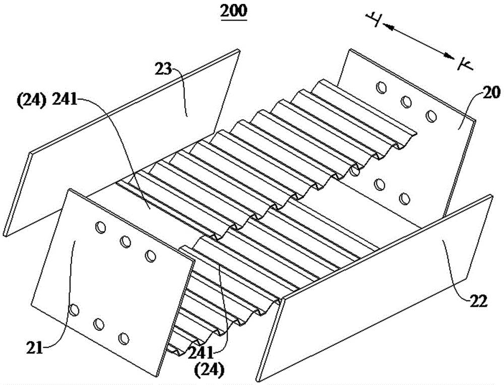
图3是根据本实用新型实施例的波纹钢板连梁阻尼器在一视角的结构示意图,其中,波纹钢板为竖向双钢板;Fig. 3 is a structural schematic diagram of a corrugated steel plate coupling beam damper according to an embodiment of the present invention at a viewing angle, wherein the corrugated steel plate is a vertical double steel plate;
图4是根据本实用新型实施例的波纹钢板连梁阻尼器在另一视角的结构示意图,其中,波纹为竖向;Fig. 4 is a structural schematic diagram of a corrugated steel plate coupling beam damper according to an embodiment of the present invention at another viewing angle, wherein the corrugation is vertical;
图5是根据本实用新型实施例的波纹钢板连梁阻尼器爆炸示意图,其中,波纹为横向;Fig. 5 is a schematic diagram of explosion of a corrugated steel plate coupling beam damper according to an embodiment of the present invention, wherein the corrugation is horizontal;
图6是根据本实用新型实施例的波纹钢板连梁阻尼器在另一视角的爆炸示意图,其中,波纹钢板为横向单钢板;Fig. 6 is an exploded schematic diagram of a corrugated steel plate coupling beam damper according to an embodiment of the present invention at another viewing angle, wherein the corrugated steel plate is a horizontal single steel plate;
图7是根据本实用新型实施例的波纹钢板连梁阻尼器在一视角的结构示意图,其中,波纹钢板为横向双钢板;Fig. 7 is a structural schematic diagram of a corrugated steel plate coupling beam damper according to an embodiment of the present invention at a viewing angle, wherein the corrugated steel plate is a transverse double steel plate;
图8是根据本实用新型实施例的波纹钢板连梁阻尼器在另一视角的结构示意图,其中,波纹为横向。Fig. 8 is a structural schematic diagram of a corrugated steel plate coupling beam damper according to an embodiment of the present invention at another viewing angle, wherein the corrugation is transverse.
附图标记:Reference signs:
波纹钢板连梁阻尼器200,第一端板20,第二端板21,第一盖板22,第二盖板23,波纹钢板24,梯形波纹241。Corrugated steel plate
具体实施方式Detailed ways
在本实用新型的描述中,需要理解的是,术语“中心”、“竖向”、“横向”、“长度”、“宽度”、“厚度”、“上”、“下”、“前”、“后”、“左”、“右”、“竖直”、“水平”、“顶”、“底”“内”、“外”、“顺时针”、“逆时针”、“轴向”、“径向”、“周向”等指示的方位或位置关系为基于附图所示的方位或位置关系,仅是为了便于描述本实用新型和简化描述,而不是指示或暗示所指的装置或元件必须具有特定的方位、以特定的方位构造和操作,因此不能理解为对本实用新型的限制。此外,限定有“第一”、“第二”的特征可以明示或者隐含地包括一个或者更多个该特征。在本实用新型的描述中,除非另有说明,“多个”的含义是两个或两个以上。In describing the present invention, it should be understood that the terms "center", "vertical", "transverse", "length", "width", "thickness", "upper", "lower", "front" , "Back", "Left", "Right", "Vertical", "Horizontal", "Top", "Bottom", "Inner", "Outer", "Clockwise", "Counterclockwise", "Axial ", "radial", "circumferential" and other indicated orientations or positional relationships are based on the orientations or positional relationships shown in the drawings, which are only for the convenience of describing the utility model and simplifying the description, rather than indicating or implying No device or element must have a specific orientation, be constructed and operate in a specific orientation, and thus should not be construed as limiting the invention. In addition, the features defined as "first" and "second" may explicitly or implicitly include one or more of these features. In the description of the present utility model, unless otherwise specified, "plurality" means two or more.
在本实用新型的描述中,需要说明的是,除非另有明确的规定和限定,术语“安装”、“相连”、“连接”应做广义理解,例如,可以是固定连接,也可以是可拆卸连接,或一体地连接;可以是机械连接,也可以是电连接;可以是直接相连,也可以通过中间媒介间接相连,可以是两个元件内部的连通。对于本领域的普通技术人员而言,可以具体情况理解上述术语在本实用新型中的具体含义。In the description of the present utility model, it should be noted that, unless otherwise clearly stipulated and limited, the terms "installation", "connection" and "connection" should be understood in a broad sense, for example, it can be a fixed connection or a flexible connection. Detachable connection, or integral connection; it can be mechanical connection or electrical connection; it can be direct connection or indirect connection through an intermediary, and it can be the internal communication of two components. Those of ordinary skill in the art can understand the specific meanings of the above terms in the present utility model in specific situations.
在本说明书的描述中,参考术语“一个实施例”、“一些实施例”、“示意性实施例”、“示例”、“具体示例”、或“一些示例”等的描述意指结合该实施例或示例描述的具体特征、结构、材料或者特点包含于本实用新型的至少一个实施例或示例中。在本说明书中,对上述术语的示意性表述不一定指的是相同的实施例或示例。而且,描述的具体特征、结构、材料或者特点可以在任何的一个或多个实施例或示例中以合适的方式结合。In the description of this specification, references to the terms "one embodiment," "some embodiments," "exemplary embodiments," "example," "specific examples," or "some examples" are intended to mean that the implementation Specific features, structures, materials or characteristics described in an embodiment or example are included in at least one embodiment or example of the present invention. In this specification, schematic representations of the above terms do not necessarily refer to the same embodiment or example. Furthermore, the specific features, structures, materials or characteristics described may be combined in any suitable manner in any one or more embodiments or examples.
下面将参考图1-图8并结合实施例来详细说明本实用新型的波纹钢板连梁阻尼器200。The corrugated steel plate
根据本实用新型实施例的波纹钢板连梁阻尼器200,包括:第一端板20、第二端板21、波纹钢板24、第一盖板22和第二盖板23。The corrugated steel plate
第一端板20和第二端板21相对设置,波纹钢板24固定连接地设置在第一端板20和第二端板21之间。第一盖板22固定连接地设置在波纹钢板24的底部,如图1、图4和图5所示上下位置,其中,下方位置为底部,波纹钢板24两端分别与第一端板20和第二端板21固定连接。第二盖板23固定连接地设置在波纹钢板24的顶部,如图1、图4和图5所示上下位置,其中,上方位置为顶部,波纹钢板24两端分别与第一端板20和第二端板21固定连接,例如采用焊接等方式。The
第一端板20和第二端板21来实现连接作用,既可以作为连梁的一部分形成完整的连梁耗能结构,又可以代替连梁连接在墙肢的中间,实现现场快速安装和震后的修复或更换。The
波纹钢板24作为波纹钢板连梁阻尼器200的耗能元件,在较大地震力作用下,可以提供稳定的力学性能,同时兼具防屈曲的功能。The
第一盖板22和第二盖板23,在波纹钢板24兼具外防屈曲功能的基础上来限制波纹钢板24的竖向位移变形使其在工作时更加稳定,同时具有保护波纹钢板24的作用。The
根据本实用新型实施例的具有波纹钢板的阻尼器,通过在连梁中设置阻尼器,保证小震下动力特性基本不变,增强在大震下的耗能性能,同时也可减轻连梁和阻尼器的损伤,安装简便,修复方便。According to the damper with corrugated steel plate in the embodiment of the utility model, by setting the damper in the connecting beam, the dynamic characteristics under small earthquakes are basically unchanged, the energy dissipation performance under large earthquakes is enhanced, and the coupling beam and the The damage of the damper is easy to install and repair.
根据本实用新型的一实施例,如图3和图7所示,波纹钢板24上具有多个连续的向内凹陷或者向外凸出的梯形波纹241。According to an embodiment of the present invention, as shown in FIGS. 3 and 7 , the
可理解的是,梯形波纹241主要产生塑性变形和起到耗散地震能量的作用,梯形波纹241将会比传统的正弦形波纹耗能能力、延性和极限承载力强,经济效应更好。通过设置梯形波纹241,改善阻尼器的屈曲特性,同时实现阻尼器承载能力增强。It is understandable that the
在一些实施例中,如图5-图8所示,梯形波纹241为横纹,朝着波纹钢板24的长度方向延伸。In some embodiments, as shown in FIGS. 5-8 , the
可理解的是,横向梯形波纹241主要产生塑性变形和起到耗散地震能量的作用。梯形波纹241在波纹钢板24上沿着波纹钢板24伸长的方向延伸,或朝第一端板20和第二端板21相对设置的方向延伸,由此使具有梯形波纹241的波纹钢板24的耗能性能、延性和极限承载能力增强,使得阻尼器的承载能力增强。It can be understood that the transverse
在一些实施例中,如图1-图4所示,梯形波纹241为竖纹,朝着波纹钢板24的横向,即高度方向延伸。In some embodiments, as shown in FIGS. 1-4 , the
可理解的是,梯形波纹241不仅可以朝着波纹钢板24伸长的方向延伸或朝第一端板20和第二端板21相对设置的方向延伸,还可以朝着波纹钢板24宽度的方向延伸或者朝着第一盖板22和第二盖板23相对设置的方向延伸,也就是说梯形波纹241不仅可以横向延伸,也可以竖向延伸,总之,梯形波纹241主要产生塑性变形和起到耗散地震能量的作用,都能够增强阻尼器的承载能力,同时也能实现大震后维修或者更换方便。It can be understood that the
实际工程中连梁的跨高比较小,容易发生剪切破坏,使用具有波纹的波纹钢板24代替普通的金属构造,从而改变连梁的剪切屈服。波纹钢板连梁阻尼器200体积较小,可以在不影响建筑使用功能的基础上进行灵活的布置。在较大地震来临时,阻尼器受到损坏后容易更换。In actual engineering, the span height of the coupling beam is relatively small, and shear failure is prone to occur. The
根据本实用新型的一实施例,如图1-图5所示,波纹钢板24包括两个,两个波纹钢板24间隔相对设置。由此增强阻尼器的承载能力和耗能能力。According to an embodiment of the present invention, as shown in FIGS. 1-5 , there are two
根据本实用新型的一实施例,波纹钢板24包括一个,一个波纹钢板24固定连接地设置在第一端板20和第二端板21中间位置。在满足要求的前提下简化结构,节省材料。According to an embodiment of the present invention, the
根据本实用新型的一实施例,第一端板20和第二端板21上均开设有螺栓孔,借助螺栓与连梁定位孔配合,由此实现波纹钢板连梁阻尼器200的定位和安装,安装简单,无需焊接。According to an embodiment of the present invention, the
在一些实施例中,第一端板20和第二端板21上至少均开设有六个定位孔,六个定位孔之间间隔设置。In some embodiments, at least six positioning holes are opened on each of the
在一些实施例中,第一端板20和第二端板21的结构相同。第一盖板22和第二盖板23的结构相同。第一盖板22和第二盖板23可起到约束波纹钢板24竖向变形的作用。In some embodiments, the
由本实用新型提供的波纹钢板连梁阻尼器可以看见:The corrugated steel plate coupling beam damper provided by the utility model can be seen:
(1)通过引入端板来实现连接,既可以作为连梁的一部分形成完整的连梁耗能结构,又可以代替连梁连接在墙肢的中间,实现实际工程中现场的快速安装和震后的修复更换。(1) The connection is realized by introducing the end plate, which can be used as a part of the connecting beam to form a complete energy-dissipating structure of the connecting beam, and can also be connected in the middle of the wall instead of the connecting beam, so as to realize rapid installation on site in actual engineering and post-earthquake repair replacement.
(2)通过引入波纹钢板作为连梁阻尼器的耗能元件,具体可分为横纹和竖纹两种类型。在较大地震力作用下,可以提供稳定的力学性能兼具防屈曲的功能。(2) By introducing corrugated steel plate as the energy dissipation element of the coupling beam damper, it can be divided into two types: horizontal grain and vertical grain. Under the action of large earthquake force, it can provide stable mechanical properties and anti-buckling function.
(3)通过引入盖板在波纹钢板兼具面外防屈曲功能的基础上来限制波纹钢板的竖向位移变形使其在工作时更加稳定,同时具有保护内部波纹钢板的作用。(3) The vertical displacement and deformation of the corrugated steel plate are limited by the introduction of the cover plate on the basis of the corrugated steel plate having the anti-buckling function outside the plane, so that it is more stable during work, and at the same time it has the function of protecting the internal corrugated steel plate.
本实用新型波纹钢板连梁阻尼器的工作机理如下:The working mechanism of the utility model corrugated steel plate coupling beam damper is as follows:
多遇地震下,阻尼器保持弹性工作状态,几乎不提供附加阻尼比,小震动力特性基本保护不变。Under frequent earthquakes, the damper maintains an elastic working state, almost does not provide additional damping ratio, and the mechanical characteristics of small shocks are basically protected.
设防地震下,阻尼器发生进入工作状态并发生屈服,塑性变形下的滞回耗能特性为结构提供附加阻尼比,对楼层剪力和底部墙肢拉应力起到一定的改善作用。Under the fortification earthquake, the damper enters the working state and yields. The hysteretic energy dissipation characteristics under the plastic deformation provide an additional damping ratio for the structure, and play a certain role in improving the shear force of the floor and the tensile stress of the bottom wall.
罕遇地震下,阻尼器进一步产生较大的塑性变形,因为波纹钢板的防屈曲性能强,阻尼器保持良好的工作状态,在塑性变形下耗散大量的地震能量,对剪力墙起到良好的保护作用。Under rare earthquakes, the damper further produces larger plastic deformation, because the corrugated steel plate has strong anti-buckling performance, the damper maintains a good working condition, and dissipates a large amount of seismic energy under plastic deformation, which plays a good role in the shear wall. protective effect.
需要说明的是,在不冲突的情况下,本实用新型中的实施例及实施例中的特征可以相互组合。It should be noted that, in the case of no conflict, the embodiments of the present invention and the features in the embodiments can be combined with each other.
以上所述仅为本实用新型的较佳实施例而已,并不用以限制本实用新型,凡在本实用新型的精神和原则之内,所作的任何修改、等同替换、改进等,均应包含在本实用新型的保护范围之内。The above descriptions are only preferred embodiments of the present utility model, and are not intended to limit the present utility model. Any modifications, equivalent replacements, improvements, etc. made within the spirit and principles of the present utility model shall be included in the Within the protection scope of the present utility model.
Claims (9)
Priority Applications (1)
| Application Number | Priority Date | Filing Date | Title |
|---|---|---|---|
| CN202223439754.6U CN218438556U (en) | 2022-12-22 | 2022-12-22 | Corrugated steel plate coupling beam damper |
Applications Claiming Priority (1)
| Application Number | Priority Date | Filing Date | Title |
|---|---|---|---|
| CN202223439754.6U CN218438556U (en) | 2022-12-22 | 2022-12-22 | Corrugated steel plate coupling beam damper |
Publications (1)
| Publication Number | Publication Date |
|---|---|
| CN218438556U true CN218438556U (en) | 2023-02-03 |
Family
ID=85074027
Family Applications (1)
| Application Number | Title | Priority Date | Filing Date |
|---|---|---|---|
| CN202223439754.6U Active CN218438556U (en) | 2022-12-22 | 2022-12-22 | Corrugated steel plate coupling beam damper |
Country Status (1)
| Country | Link |
|---|---|
| CN (1) | CN218438556U (en) |
Cited By (2)
| Publication number | Priority date | Publication date | Assignee | Title |
|---|---|---|---|---|
| CN117188645A (en) * | 2023-09-23 | 2023-12-08 | 广州大学 | A circular wave corrugated steel plate damper |
| CN117328570A (en) * | 2023-08-31 | 2024-01-02 | 西安理工大学 | High-strength steel nodes with corrugated energy dissipators and double damage elements with anti-buckling function |
-
2022
- 2022-12-22 CN CN202223439754.6U patent/CN218438556U/en active Active
Cited By (2)
| Publication number | Priority date | Publication date | Assignee | Title |
|---|---|---|---|---|
| CN117328570A (en) * | 2023-08-31 | 2024-01-02 | 西安理工大学 | High-strength steel nodes with corrugated energy dissipators and double damage elements with anti-buckling function |
| CN117188645A (en) * | 2023-09-23 | 2023-12-08 | 广州大学 | A circular wave corrugated steel plate damper |
Similar Documents
| Publication | Publication Date | Title |
|---|---|---|
| CN207646932U (en) | A kind of arc panel, corrugated sheet steel and spring assembly consume energy mild steel damper | |
| CN111335145B (en) | Displacement-amplified multi-dimensional energy dissipation device for preventing plastic hinges at the ends of bridge piers | |
| CN109853770A (en) | A kind of Self-resetting bouble-bow is to drawing dual energy dissipation brace device | |
| CN114293674B (en) | Connecting beam with SMA friction composite damper and SMA friction composite damper | |
| CN208184005U (en) | A kind of vertical restricted type metal yield energy-consumption damper of release | |
| CN113494143B (en) | Corrugated steel plate wall-rotating lead damper dual-function composite shock absorption device and its dual-stage anti-seismic control method | |
| CN110145056A (en) | Prefabricated laminated corrugated steel plate energy dissipation shear wall | |
| CN111287344A (en) | Shock-absorbing and collapse-preventing combined structure | |
| CN207453080U (en) | A kind of semi-girder truss and Frame-Shear wall | |
| CN118127980A (en) | High-pile wharf toughness anti-seismic system and installation method thereof | |
| CN104294919B (en) | Ring boxlike power consumption net shell node | |
| CN219654007U (en) | Double-layer viscous damping wall structure system suitable for concrete structure | |
| CN207453259U (en) | A kind of coupling beam construction between shear wall structure wall limb | |
| CN218757513U (en) | Interlayer shock absorption and shock insulation double-wire-proof system | |
| CN112647600A (en) | External metal damper combined rubber shock insulation support and installation and maintenance method thereof | |
| CN217268340U (en) | Energy dissipation is roof beam even with viscous damper connecting device | |
| CN107859404A (en) | A kind of metal energy-dissipation damper | |
| CN111218999A (en) | A metal and spring rubber composite damper | |
| CN215630854U (en) | A prefabricated steel frame-energy-consuming trapezoidal corrugated steel plate wall | |
| CN107859196B (en) | A replaceable assembled energy dissipation and vibration reduction node with self-resetting function | |
| CN213204551U (en) | Soft steel energy dissipater with elliptic holed energy dissipation plate and parabolic energy dissipation plate cooperatively applied | |
| CN211115079U (en) | Friction pendulum energy dissipation and shock isolation device with multistage overturn prevention function | |
| CN118668833B (en) | Multi-stage yielding metal damper and damping method thereof | |
| CN210031473U (en) | One-way energy-consumption beam falling prevention device | |
| CN108691429A (en) | Assembling frame node anti-seismic strengthening device and its construction method |
Legal Events
| Date | Code | Title | Description |
|---|---|---|---|
| GR01 | Patent grant | ||
| GR01 | Patent grant | ||
| CP03 | Change of name, title or address |
Address after: 100045 Beijing city Xicheng District South Road No. 62 Patentee after: Beijing Institute of Architectural Design and Research Co.,Ltd. Country or region after: China Address before: 100045 Beijing city Xicheng District South Road No. 62 Patentee before: BEIJING INSTITUTE OF ARCHITECTURAL DESIGN Country or region before: China |