CN218434609U - Gantry crane for girder erection construction - Google Patents
Gantry crane for girder erection construction Download PDFInfo
- Publication number
- CN218434609U CN218434609U CN202221699584.2U CN202221699584U CN218434609U CN 218434609 U CN218434609 U CN 218434609U CN 202221699584 U CN202221699584 U CN 202221699584U CN 218434609 U CN218434609 U CN 218434609U
- Authority
- CN
- China
- Prior art keywords
- crane
- wire rope
- equipment
- wheel
- walking
- Prior art date
- Legal status (The legal status is an assumption and is not a legal conclusion. Google has not performed a legal analysis and makes no representation as to the accuracy of the status listed.)
- Active
Links
- 238000010276 construction Methods 0.000 title claims abstract description 16
- 229910000831 Steel Inorganic materials 0.000 claims description 19
- 239000010959 steel Substances 0.000 claims description 19
- 230000001681 protective effect Effects 0.000 claims description 5
- 238000004804 winding Methods 0.000 claims description 2
- 238000012423 maintenance Methods 0.000 abstract description 7
- XLYOFNOQVPJJNP-UHFFFAOYSA-N water Substances O XLYOFNOQVPJJNP-UHFFFAOYSA-N 0.000 abstract description 6
- JEIPFZHSYJVQDO-UHFFFAOYSA-N iron(III) oxide Inorganic materials O=[Fe]O[Fe]=O JEIPFZHSYJVQDO-UHFFFAOYSA-N 0.000 abstract description 2
- 230000002035 prolonged effect Effects 0.000 abstract description 2
- 238000009434 installation Methods 0.000 description 7
- 230000008093 supporting effect Effects 0.000 description 5
- 239000000463 material Substances 0.000 description 2
- 230000009286 beneficial effect Effects 0.000 description 1
- 230000007797 corrosion Effects 0.000 description 1
- 238000005260 corrosion Methods 0.000 description 1
- 230000007547 defect Effects 0.000 description 1
- 210000001503 joint Anatomy 0.000 description 1
- 230000000149 penetrating effect Effects 0.000 description 1
- 238000005406 washing Methods 0.000 description 1
Images



Landscapes
- Carriers, Traveling Bodies, And Overhead Traveling Cranes (AREA)
Abstract
The utility model discloses a portal crane is used in frame roof beam construction, including the main beam, the longeron is installed at the top of main beam, the crane rail is installed at the top of longeron, the wheel of lifting by crane is installed to the bottom of crane, lifts by crane the wheel and contacts with the crane rail, the extension roof beam is installed in the outside of main beam, the waterproof layer is installed at the top of extension roof beam, the utility model discloses an install the waterproof layer, the waterproof layer can block rainwater contact device top when raining, carries out water proof protection to the inside equipment of main beam, prevents that long-time contact rainwater from leading to equipment top to rust, corrode, has prolonged the live time of equipment to it is convenient to provide the maintenance of equipment for follow-up staff, brings the convenience for the staff.
Description
Technical Field
The utility model relates to a portal crane technical field specifically is a portal crane is used in frame roof beam construction.
Background
Gantry crane is one of the indispensable equipment when large-scale construction or transport, and it can carry, load and unload various finished goods article and form material scattered under staff's operation, and application scope is great, but traditional equipment does not accomplish finely in the aspect of corroding to rain-proof water, and the time is just corroded by the rainwater easily, reduces equipment life, and later stage maintenance, maintenance influence work efficiency, and a gantry crane for the construction of frame roof beam can provide convenient for the staff.
The defects of the gantry crane in the prior art are as follows:
1. patent documents: CN201485192U a portable bridge type portal crane, "device include electric block, electric block walking beam, portal crane support walking beam and running gear, track roof beam, operation panel, characterized by: the electric hoist is arranged on the electric hoist walking beam, the outer end of the track beam is provided with a walking platform, and the operating platform is arranged on the walking platform. The advantages are that: the construction equipment can lead various materials to enter and exit the construction working face without dead angles, and the whole equipment can be moved. The labor intensity of workers can be reduced, and the construction progress is accelerated. "traditional equipment does not accomplish very well in the aspect of corroding to rain-proof water, and long time just is corroded by the rainwater easily, reduces equipment life, and later stage maintenance, maintenance influence work efficiency.
SUMMERY OF THE UTILITY MODEL
An object of the utility model is to provide a gantry crane is used in frame roof beam construction to solve the problem that proposes among the above-mentioned background art.
In order to achieve the above object, the utility model provides a following technical scheme: a gantry crane for girder erection construction comprises a main cross beam, wherein a longitudinal beam is mounted at the top of the main cross beam, a crane rail is mounted at the top of the longitudinal beam, a crane wheel is movably mounted at the top of the crane rail, a crane is mounted on the inner side of the crane wheel, an extension beam is mounted on the outer side of the main cross beam, and a waterproof layer is mounted at the top of the extension beam;
the walking beam is installed to the bottom of main beam, the fixer is installed to the bottom of walking beam, the inside movable mounting of fixer has the walking wheel, play the inboard roof of crane and install the motor, the output swing joint of motor has the connecting rod, wire rope transceiver is installed to the one end of connecting rod, wire rope is installed in wire rope transceiver's outside winding, play the inboard bottom of crane and install the support, leg joint wire rope transceiver.
Preferably, the bottom of the main cross beam is provided with a support leg, and the support leg is arranged on one side of the walking beam.
Preferably, the bottom of the crane is provided with a receiving and dispatching opening.
Preferably, a pulley block is installed at the bottom end of the steel wire rope, and the steel wire rope penetrates through the protective shell to be connected with the pulley block.
Preferably, the bottom of the pulley block is provided with a connecting section.
Preferably, the connecting section is connected to a lifting hook.
Compared with the prior art, the beneficial effects of the utility model are as follows:
1. the utility model discloses an install the waterproof layer, the waterproof layer can block rainwater contact device top when raining, carries out water proof to the inside equipment of main beam, prevents that long-time contact rainwater from leading to equipment top to rust, corrode, has prolonged the live time of equipment to it is convenient to provide the maintenance of equipment for follow-up staff, brings the convenience for the staff.
2. The utility model discloses an install the fixer, the fixer is installed in the walking wheel outside, when equipment removes to suitable position, stops to remove to put down the fixer, the fixer can block the wheel after putting down and fix, prevents that other factors from leading to equipment to remove, has brought safety and convenient for the staff.
Drawings
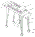
Fig. 1 is a perspective view of a gantry crane of the present invention;
FIG. 2 is a cross-sectional view of a gantry crane of the present invention;
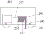
FIG. 3 is a cross-sectional view of the hoist of the present invention;
fig. 4 is a cross-sectional view of the lifting wheel and the rail of the present invention;
fig. 5 is a perspective view of the present invention without a waterproof layer.
In the figure: 1. a main cross beam; 101. a walking beam; 102. a support leg; 103. a holder; 104. a traveling wheel; 105. a stringer; 106. lifting the crane rail; 107. an extension beam; 2. lifting the crane; 201. hoisting the wheel; 202. a motor; 203. a connecting rod; 204. a wire rope receiving and transmitting device; 205. a support; 206. a transceiver port; 207. a wire rope; 3. a waterproof layer; 4. a protective shell; 401. a pulley block; 402. a connecting section; 403. a lifting hook is provided.
Detailed Description
The technical solutions in the embodiments of the present invention will be described clearly and completely with reference to the drawings in the embodiments of the present invention, and it is obvious that the described embodiments are only some embodiments of the present invention, not all embodiments. Based on the embodiments in the present invention, all other embodiments obtained by a person skilled in the art without creative efforts belong to the protection scope of the present invention.
In the description of the present invention, it should be noted that the terms "upper", "lower", "inner", "outer", "front", "rear", "both ends", "one end", "the other end", and the like indicate orientations or positional relationships based on the orientations or positional relationships shown in the drawings, and are only for convenience of description and simplification of the description, but do not indicate or imply that the device or element referred to must have a specific orientation, be constructed and operated in a specific orientation, and thus, should not be construed as limiting the present invention. Furthermore, the terms "first," "second," and the like are used for descriptive purposes only and are not to be construed as indicating or implying relative importance.
In the description of the present invention, it is to be noted that, unless otherwise explicitly specified or limited, the terms "mounted," "disposed," "connected," and the like are to be construed broadly, and for example, "connected" may be either fixedly connected or detachably connected, or integrally connected; can be mechanically or electrically connected; they may be connected directly or indirectly through intervening media, or they may be interconnected between two elements. The specific meaning of the above terms in the present invention can be understood in specific cases to those skilled in the art.
Referring to fig. 1, 2, 3, 4 and 5, a gantry crane for erecting a girder is provided;
the waterproof structure comprises a main cross beam 1, a walking beam 101 is installed at the bottom of the main cross beam 1, supporting legs 102 are installed at the bottom of the main cross beam 1, the bottom ends of the supporting legs 102 are installed on one side of the walking beam 101, the walking beam 101 can support the main cross beam 1 and can move as required, the supporting legs 102 can help the walking beam 101 to share bearing force, meanwhile, the supporting legs 102 can bring supporting effect to the main cross beam 1, an extension beam 107 is installed on the outer side of the main cross beam 1, a waterproof layer 3 is installed at the top of the extension beam 107, the main cross beam 1 provides installation support for the extension beam 107 installed on the outer side, the extension beam 107 can provide support for installation of the waterproof layer 3 installed at the top, the waterproof layer 3 can carry out waterproof protection on equipment inside the main cross beam 1 in rainy days, the equipment is prevented from rusting and corrosion due to long-time rain washing, the service life of the equipment is prevented, the longitudinal beams 105 are installed at the top of the main cross beam 1, the top of the longitudinal beam 105 is provided with a crane rail 106, the top of the crane rail 106 is movably provided with a crane wheel 201, the inner side of the crane wheel 201 is provided with a crane 2, the main cross beam 1 provides support for the installation of the longitudinal beam 105, the longitudinal beam 105 supports the crane rail 106 arranged at the top, the crane rail 106 can be used for the movement of the crane 2, the crane wheel 201 arranged at the bottom of the crane 2 is in contact with the crane rail 106, the top wall of the inner side of the crane 2 is provided with a motor 202, the output end of the motor 202 is movably provided with a connecting rod 203, one end of the connecting rod 203 is provided with a steel wire rope transceiver 204, the bottom of the inner side of the crane 2 is provided with a bracket 205, the bracket 205 is connected with the steel wire rope transceiver 204, the bottom of the crane 2 is provided with a transceiver 206, and the outer side of the steel wire rope transceiver 204 is wound with a steel wire rope 207, the crane 2 provides a space for the internally installed motor 202, the motor 202 is connected with the steel wire rope transceiver 204 through the connecting rod 203, the motor 202 provides power for the steel wire rope transceiver 204, the support 205 provides support for the steel wire rope transceiver 204 to prevent the device from falling off, the steel wire rope transceiver 204 can control the transceiving of the steel wire rope 207, the steel wire rope 207 enters and exits from the transceiving opening 206, the bottom end of the steel wire rope 207 is provided with a pulley block 401, the steel wire rope 207 penetrates through the protective shell 4 and is connected with the pulley block 401, the bottom of the pulley block 401 is provided with a connecting section 402, the connecting section 402 is connected with the hoisting hook 403, the steel wire rope 207 penetrating through the transceiving opening 206 penetrates through the protective shell 4 installed on the outer side of the pulley block 401 and is connected with the pulley block 401, the connecting section 402 installed at the bottom of the pulley block 401 can connect the pulley block 401 with the hoisting hook 403, and the pulley block 401 and the following parts are controlled by the steel wire rope transceiver 204 through the steel wire rope 207 after connection.
Referring to fig. 1 and 2, a gantry crane for erecting a girder;
Referring to fig. 1, 2 and 5, a gantry crane for girder erection construction;
the bottom of walking beam 101 is installed fixer 103, and the inside movable mounting of fixer 103 has walking wheel 104, and when walking wheel 104 stopped to remove, will install the fixer 103 in the walking wheel 104 outside and put down, fixes walking wheel 104, prevents that other factors from leading to the equipment removal.
The working principle is as follows: rainwater can be installed and block at the waterproof layer 3 at extension roof beam 107 top when raining, and waterproof layer 3 can carry out water proof to the equipment of main beam 1 inside in rainy day, prevents rainwater and equipment top contact to cause getting rusty, the corruption of equipment, influence equipment life, for the staff provides convenience and swift to the maintenance in equipment later stage.
It is obvious to a person skilled in the art that the invention is not restricted to details of the above-described exemplary embodiments, but that it can be implemented in other specific forms without departing from the spirit or essential characteristics of the invention. The present embodiments are therefore to be considered in all respects as illustrative and not restrictive, the scope of the invention being indicated by the appended claims rather than by the foregoing description, and all changes which come within the meaning and range of equivalency of the claims are therefore intended to be embraced therein. Any reference sign in a claim should not be construed as limiting the claim concerned.
Claims (6)
1. The utility model provides a portal crane is used in frame roof beam construction, includes main beam (1), its characterized in that: a longitudinal beam (105) is installed at the top of the main cross beam (1), a crane rail (106) is installed at the top of the longitudinal beam (105), a crane wheel (201) is movably installed at the top of the crane rail (106), a crane (2) is installed on the inner side of the crane wheel (201), an extension beam (107) is installed on the outer side of the main cross beam (1), and a waterproof layer (3) is installed at the top of the extension beam (107);
walking roof beam (101) are installed to the bottom of main beam (1), fixer (103) are installed to the bottom of walking roof beam (101), the inside movable mounting of fixer (103) has walking wheel (104), motor (202) are installed to the inboard roof that plays crane (2), the output swing joint of motor (202) has connecting rod (203), wire rope transceiver (204) are installed to the one end of connecting rod (203), wire rope (207) are installed in the outside winding of wire rope transceiver (204), support (205) are installed to the inboard bottom that plays crane (2), and wire rope transceiver (204) are connected in support (205).
2. The gantry crane for the construction of the frame beam as claimed in claim 1, wherein: the bottom of the main cross beam (1) is provided with a support leg (102), and the support leg (102) is arranged on one side of the walking beam (101).
3. The gantry crane for frame beam construction according to claim 1, wherein: the bottom of the crane (2) is provided with a receiving and dispatching port (206).
4. The gantry crane for the construction of the frame beam as claimed in claim 1, wherein: a pulley block (401) is installed at the bottom end of the steel wire rope (207), and the steel wire rope (207) penetrates through the protective shell (4) to be connected with the pulley block (401).
5. The gantry crane for girder erection according to claim 4, wherein: the bottom of the pulley block (401) is provided with a connecting section (402).
6. The gantry crane for girder erection according to claim 5, wherein: the connecting section (402) is connected with a lifting hook (403).
Priority Applications (1)
| Application Number | Priority Date | Filing Date | Title |
|---|---|---|---|
| CN202221699584.2U CN218434609U (en) | 2022-07-04 | 2022-07-04 | Gantry crane for girder erection construction |
Applications Claiming Priority (1)
| Application Number | Priority Date | Filing Date | Title |
|---|---|---|---|
| CN202221699584.2U CN218434609U (en) | 2022-07-04 | 2022-07-04 | Gantry crane for girder erection construction |
Publications (1)
| Publication Number | Publication Date |
|---|---|
| CN218434609U true CN218434609U (en) | 2023-02-03 |
Family
ID=85088340
Family Applications (1)
| Application Number | Title | Priority Date | Filing Date |
|---|---|---|---|
| CN202221699584.2U Active CN218434609U (en) | 2022-07-04 | 2022-07-04 | Gantry crane for girder erection construction |
Country Status (1)
| Country | Link |
|---|---|
| CN (1) | CN218434609U (en) |
-
2022
- 2022-07-04 CN CN202221699584.2U patent/CN218434609U/en active Active
Similar Documents
| Publication | Publication Date | Title |
|---|---|---|
| CN209397501U (en) | Deck crane | |
| CN2937068Y (en) | Portal crane of round pipe truss structure | |
| CN101693495A (en) | Construction hoist | |
| CN205709568U (en) | A kind of intelligent remote controls full-automatic explosion-proof type tank container gantry | |
| CN108706471B (en) | Method for disassembling rigid leg of large gantry crane | |
| CN216889795U (en) | Gantry crane system for GIL installation | |
| CN215629431U (en) | Longitudinal prestressed tendon tensioning trolley for suspension casting box girder | |
| CN214570326U (en) | Curtain wall unit plate rail hoisting and hard protection integrated device | |
| CN220432078U (en) | Single girder gantry crane | |
| CN216809835U (en) | Vertical type rapid assembling device for offshore wind power jacket | |
| CN214882988U (en) | Aerial rotary lifting appliance for lifting and mounting steel box girder of suspension bridge | |
| CN215518418U (en) | Prestressed cover beam tensioning hanging basket | |
| CN222576092U (en) | Movable mounting platform for mounting steel structure wallboard | |
| CN224244382U (en) | Hanging basket capable of transversely moving and turning | |
| CN216807806U (en) | Sewage treatment plant photovoltaic power generation supports steel construction conveyor system | |
| CN113833180A (en) | Mounting construction method for main keel of hanging three-limb combined curtain wall | |
| CN220116071U (en) | Travelling car operation platform | |
| CN206917297U (en) | A kind of large-span steel girder upper air installing system in place | |
| CN220056126U (en) | Curtain wall hoisting and installing system | |
| CN211078293U (en) | High-altitude hoisting prefabricated part symmetrical equipment | |
| CN216235766U (en) | High-rise building steel vestibule hoisting device | |
| CN220057640U (en) | A kind of rail-type bridge cast-in-place railing construction platform | |
| CN221027267U (en) | Truss type annular track lifting device for glass curtain wall roof | |
| CN217461538U (en) | A steel platform of unloading of encorbelmenting for assembly type structure construction | |
| CN222974715U (en) | Portal crane |
Legal Events
| Date | Code | Title | Description |
|---|---|---|---|
| GR01 | Patent grant | ||
| GR01 | Patent grant |