CN218427347U - Plate sanding machine - Google Patents
Plate sanding machine Download PDFInfo
- Publication number
- CN218427347U CN218427347U CN202222736440.6U CN202222736440U CN218427347U CN 218427347 U CN218427347 U CN 218427347U CN 202222736440 U CN202222736440 U CN 202222736440U CN 218427347 U CN218427347 U CN 218427347U
- Authority
- CN
- China
- Prior art keywords
- frame
- underframe
- bottom frame
- wall
- sanding
- Prior art date
- Legal status (The legal status is an assumption and is not a legal conclusion. Google has not performed a legal analysis and makes no representation as to the accuracy of the status listed.)
- Active
Links
- 239000004576 sand Substances 0.000 claims abstract description 12
- 239000000463 material Substances 0.000 claims abstract description 7
- 239000003381 stabilizer Substances 0.000 claims abstract 2
- 230000005540 biological transmission Effects 0.000 claims description 16
- 230000003014 reinforcing effect Effects 0.000 claims description 5
- 230000000149 penetrating effect Effects 0.000 claims description 4
- 238000000034 method Methods 0.000 description 9
- 238000009434 installation Methods 0.000 description 8
- 238000007599 discharging Methods 0.000 description 6
- 239000002023 wood Substances 0.000 description 5
- 238000005034 decoration Methods 0.000 description 4
- 239000002699 waste material Substances 0.000 description 4
- 230000006978 adaptation Effects 0.000 description 2
- 238000004519 manufacturing process Methods 0.000 description 2
- 230000004075 alteration Effects 0.000 description 1
- 230000009286 beneficial effect Effects 0.000 description 1
- 238000010586 diagram Methods 0.000 description 1
- 230000000694 effects Effects 0.000 description 1
- 238000004880 explosion Methods 0.000 description 1
- 238000003754 machining Methods 0.000 description 1
- 238000012986 modification Methods 0.000 description 1
- 230000004048 modification Effects 0.000 description 1
- 238000006467 substitution reaction Methods 0.000 description 1
Images


Classifications
-
- Y—GENERAL TAGGING OF NEW TECHNOLOGICAL DEVELOPMENTS; GENERAL TAGGING OF CROSS-SECTIONAL TECHNOLOGIES SPANNING OVER SEVERAL SECTIONS OF THE IPC; TECHNICAL SUBJECTS COVERED BY FORMER USPC CROSS-REFERENCE ART COLLECTIONS [XRACs] AND DIGESTS
- Y02—TECHNOLOGIES OR APPLICATIONS FOR MITIGATION OR ADAPTATION AGAINST CLIMATE CHANGE
- Y02P—CLIMATE CHANGE MITIGATION TECHNOLOGIES IN THE PRODUCTION OR PROCESSING OF GOODS
- Y02P70/00—Climate change mitigation technologies in the production process for final industrial or consumer products
- Y02P70/10—Greenhouse gas [GHG] capture, material saving, heat recovery or other energy efficient measures, e.g. motor control, characterised by manufacturing processes, e.g. for rolling metal or metal working
Landscapes
- Finish Polishing, Edge Sharpening, And Grinding By Specific Grinding Devices (AREA)
Abstract
The utility model relates to a grinder technical field just discloses a panel grinder, including the underframe, the material loading platform is installed to the left surface of underframe, the unloading platform is installed to the right flank of underframe, the stabilizer blade is all installed to both sides around material loading platform and the unloading platform lower surface, the middle part of underframe bottom inner wall is provided with collects the fill, the blown down tank has been seted up at the middle part of underframe lower surface, the middle part of underframe lower surface is provided with the collecting box. This panel grinder drives through hydraulic push rod and removes the frame and goes up and down for remove the frame and drive the sand light cylinder and go up and down, realized the regulation to sand light cylinder height, make the user can adjust the height of sand light cylinder according to the user demand, make the device can be applicable to the processing of different thickness panels, increased the application range of device, improved the practicality of device, the user of being convenient for uses the device.
Description
Technical Field
The utility model relates to a grinder technical field specifically is a panel grinder.
Background
The wood board is a wood board made of complete wood, the wood board is firm and durable, has natural grains, is selected from the best decoration, has high manufacturing cost, is generally classified according to the substantial names of the wood boards, does not have uniform standard specifications, is a material frequently used in home decoration, is an ideal material for ground decoration of bedrooms, living rooms, study rooms and the like, and is generally subjected to sanding treatment in the processing process; the sand light makes the surface of the board smooth and increases the surface strength, the thickness is uniform and consistent, and the sand light is suitable for various veneering processes, various standard structural parts and convenient for decoration and furniture manufacture; the sanding machine in the prior art is generally complex in structure, and the sanding roller is difficult to adjust the height so as not to adapt to the processing of plates of different specifications, and the adaptability is poor, so that the application range of the sanding machine is reduced.
SUMMERY OF THE UTILITY MODEL
Technical problem to be solved
Not enough to prior art, the utility model provides a panel grinder has solved the problem that proposes among the above-mentioned background art.
(II) technical scheme
In order to achieve the above object, the utility model provides a following technical scheme: a plate sander comprises a bottom frame, wherein a feeding table is installed on the left side surface of the bottom frame, a discharging table is installed on the right side surface of the bottom frame, support legs are installed on the front side and the rear side of the lower surfaces of the feeding table and the discharging table respectively, a collecting hopper is arranged in the middle of the inner wall of the bottom frame, a discharging groove is formed in the middle of the lower surface of the bottom frame, a collecting box is arranged in the middle of the lower surface of the bottom frame, mounting legs are installed in the middle of the front surface and the back surface of the collecting box respectively, mounting bolts penetrate through the middle of the outer side surface of the mounting legs, one end threads penetrating into the mounting legs are arranged on the bottom frame, the top of the inner wall of the front side of the bottom frame is rotatably connected with a conveying roller, a first transmission rod is installed in the middle of the back surface of the conveying roller, chain wheels are installed at the rear ends of the first transmission rod, fifteen groups of chain wheels are connected through chain transmission, the utility model discloses a sanding machine, including underframe, underframe front surface, baffle, sanding cylinder, underframe front side inner wall, underframe rear surface, underframe front surface, underframe rear surface, underframe front side's left side is installed the U-shaped frame, the left side of U-shaped frame top inner wall is provided with hydraulic rod, hydraulic rod's output is connected with removes the frame, the baffle is all installed to both sides around removing frame upper surface and lower surface, the middle part of removing frame front side inner wall rotates and is connected with the sanding cylinder, the mid-mounting at the sanding cylinder back has the second transfer line, the drive wheel has been cup jointed on the second transfer line, four groups the drive wheel passes through belt transmission and connects, the positive right side of removal frame is provided with first driving motor, first driving motor's output and the front end key connection of the sanding cylinder that is located the right side, the positive right side of underframe is provided with second driving motor, second driving motor's output and the front end key connection of the conveying roller that is located the right side.
Preferably, the bottom of the front surface and the back surface of the bottom frame and the middle of the outer side surface of the mounting foot are provided with threaded holes, and the inner diameter of each threaded hole is matched with the outer diameter of the mounting bolt.
Preferably, the shape of the collecting hopper is hollow trapezoid, and the top of the outer side surface of the collecting hopper is fixedly connected with the middle of the inner wall of the bottom frame.
Preferably, the front side and the rear side of the right side face of the U-shaped frame are fixedly connected with reinforcing rods, and the bottom ends of the reinforcing rods are fixedly connected with the upper surface of the bottom frame.
Preferably, the front side and the rear side of the upper surface of the U-shaped frame are both provided with a moving groove, and the width of the moving groove is matched with that of the baffle.
Preferably, the square blocks are fixedly connected to the middle portions of the inner wall on the left side and the inner wall on the right side of the U-shaped frame, and square grooves are formed in the front side and the rear side of the left side face and the rear side of the movable frame.
(III) advantageous effects
Compared with the prior art, the utility model provides a panel grinder possesses following beneficial effect:
1. this panel grinder drives through hydraulic pressure push rod and removes the frame and goes up and down for removing the frame and driving the sand light cylinder and go up and down, realized the regulation to sand light cylinder height, make the user can adjust the height of sand light cylinder according to the user demand, make the device can be applicable to the processing of different thickness panels, increased the application range of device, improved the practicality of device, the user of being convenient for uses the device.
2. This panel grinder, through setting up the baffle for when removing the frame and removing, the baffle can block removing the produced clearance of in-process, has reduced the produced sweeps in the course of working and has taken place the probability that the phenomenon appears that splashes, provides a good operational environment for the staff, through setting up collection fill and collecting box, has realized the quick collection to the produced sweeps in the course of working, has accelerated the collection speed to the sweeps, has improved work efficiency.
3. This panel grinder through setting up mounting bolt, has realized the quick installation or the dismantlement to the collecting box for the user can install or dismantle the collecting box according to the user demand, has made things convenient for the user to handle the sweeps that the collecting box is inside collected, has guaranteed the normal use of collecting box, drives the conveying roller through second driving motor and rotates, makes the conveying roller carry panel, has realized carrying the automation of panel, has improved work efficiency.
Drawings
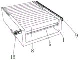
FIG. 1 is a schematic structural view of the present invention;
FIG. 2 is a schematic view of a partial structure of the present invention;
fig. 3 is a schematic diagram of the local structure explosion of the present invention.
In the figure: 1. a bottom frame; 2. a feeding table; 3. a blanking table; 4. a leg; 5. a collecting hopper; 6. a collection box; 7. installing a bolt; 8. a conveying roller; 9. a sprocket; 10. a U-shaped frame; 11. a hydraulic push rod; 12. moving the frame; 13. a baffle plate; 14. sanding the roller; 15. a first drive motor; 16. a second drive motor.
Detailed Description
The technical solutions in the embodiments of the present invention will be described clearly and completely with reference to the drawings in the embodiments of the present invention, and it is obvious that the described embodiments are only some embodiments of the present invention, not all embodiments. Based on the embodiments in the present invention, all other embodiments obtained by a person skilled in the art without creative work belong to the protection scope of the present invention.
Referring to fig. 1-3, the present invention provides a technical solution: a plate sander comprises a bottom frame 1, a feeding table 2 is installed on the left side surface of the bottom frame 1, a discharging table 3 is installed on the right side surface of the bottom frame 1, support legs 4 are installed on the front side and the rear side of the lower surfaces of the feeding table 2 and the discharging table 3, a collecting hopper 5 is arranged in the middle of the inner wall of the bottom frame 1, a discharging groove is formed in the middle of the lower surface of the bottom frame 1, a collecting box 6 is arranged in the middle of the lower surface of the bottom frame 1, mounting legs are installed in the middle of the front side and the back side of the collecting box 6, mounting bolts 7 penetrate through the middle of the outer side surfaces of the mounting legs, one end threads of the mounting bolts 7 penetrating into the mounting legs penetrate through the bottom frame 1, a conveying roller 8 is rotatably connected to the top of the inner wall of the front side of the bottom frame 1, a first transmission rod is installed in the middle of the back side of the conveying roller 8, a chain wheel 9 is installed at the rear end of the first transmission rod, fifteen groups of chain wheels 9 are connected through chain transmission, a U-shaped frame 10 is installed on the left side of the upper surface of the bottom frame 1, a hydraulic push rod 11 is arranged on the left side of the top inner wall of the U-shaped frame 10, the movable frame 12 is driven to lift through the hydraulic push rod 11, so that the movable frame 12 drives the sanding roller 14 to lift, the height of the sanding roller 14 is adjusted, a user can adjust the height of the sanding roller 14 according to the use requirement, the device can be suitable for processing plates with different thicknesses, the use range of the device is enlarged, the practicability of the device is improved, the user can conveniently apply the device, the output end of the hydraulic push rod 11 is connected with the movable frame 12, the front side and the rear side of the upper surface and the lower surface of the movable frame 12 are respectively provided with the baffle 13, when the movable frame 12 moves, the baffle 13 can block a gap generated in the moving process, and the probability of splashing of waste scraps generated in the processing process is reduced, the working environment is good for workers, the collecting hopper 5 and the collecting box 6 are arranged, the waste scraps generated in the machining process are quickly collected, the collecting speed of the waste scraps is increased, the working efficiency is improved, the middle of the inner wall of the front side of the movable frame 12 is rotatably connected with the sanding roller 14, a second transmission rod is arranged in the middle of the back of the sanding roller 14, transmission wheels are sleeved on the second transmission rod, the four groups of transmission wheels are connected through belt transmission, the right side of the front side of the movable frame 12 is provided with a first driving motor 15, the output end of the first driving motor 15 is connected with the front end of the sanding roller 14 on the right side through a key, the right side of the front side of the bottom frame 1 is provided with a second driving motor 16, the models of the first driving motor 15 and the second driving motor 16 are Y80M1-2, the mounting bolt 7 is arranged, the collecting box 6 is quickly mounted or dismounted, a user can mount or dismount the collecting box 6 according to the use requirements, the user can conveniently process the waste scraps collected in the collecting box 6, the normal use of the collecting box, the conveying roller 8 is driven to rotate by the second driving motor 16, the conveying roller 8, the conveying roller is connected with the conveying roller, and the front end of the conveying motor 16, and the conveying efficiency of the right side is improved.
The utility model discloses a realization is fixed to the installation between underframe 1 and the installation foot, consequently all sets up threaded hole in the bottom at 1 front and the back of underframe and the middle part of installation foot lateral surface, the internal diameter of screw hole and mounting bolt 7's external diameter looks adaptation, and mounting bolt 7 fixes underframe 1 and installation foot through the screw hole.
The utility model discloses a realize the quick collection to produced sweeps in the course of working, consequently set up the shape of collecting 5 and be that fretwork form is trapezoidal, collect the middle part fixed connection of the top of fighting 5 lateral surfaces and underframe 1 inner wall, produced sweeps can drop to the inside of collecting 5 in the course of working, collect and fight 5 and collect it, realized the quick collection to produced sweeps in the course of working.
The utility model discloses a firm degree of installation between reinforcing underframe 1 and U-shaped frame 10, consequently the equal fixedly connected with anchor strut in both sides around the U-shaped frame 10 right flank, the bottom of anchor strut and the last fixed surface of underframe 1 are connected, and the anchor strut is consolidated between underframe 1 and U-shaped frame 10, has strengthened the firm degree of installation between underframe 1 and U-shaped frame 10.
The utility model discloses a realize all having seted up the shifting chute to the regulation of moving frame 12 height, consequently both sides around the U-shaped frame 10 upper surface, the width of shifting chute and the width looks adaptation of baffle 13, when highly adjusting moving frame 12, baffle 13 removes in the inside of shifting chute.
The utility model discloses a stability when guaranteeing to remove frame 12 and remove, consequently at the equal fixedly connected with square piece in the middle part of U-shaped frame 10 left side inner wall and right side inner wall, square groove has all been seted up to both sides around removing frame 12 left and right sides face, and square piece carries on spacingly through square groove to removing frame 12, has guaranteed the stability when removing frame 12 and has removed.
The electrical components presented in the document are all electrically connected with an external master controller and 220V mains, and the master controller can be a conventional known device controlled by a computer or the like.
When using, the user adjusts sanding cylinder 14's height according to the user demand, hydraulic push rod 11 is started, hydraulic push rod 11's the flexible drive of output removes frame 12 and goes up and down, it drives sanding cylinder 14 and goes up and down to remove frame 12, the regulation to sanding cylinder 14 height has been realized, after the regulation finishes, start first driving motor 15 and second driving motor 16, the rotatory sanding cylinder 14 that drives that is located the right side of output of first driving motor 15 rotates, sanding cylinder 14 that is located the right side passes through the second transfer line, belt and drive wheel drive all the other sanding cylinders 14 and rotate, second driving motor 16 drives conveying roller 8 that is located the right side and rotates, conveying roller 8 that is located the right side passes through first transfer line, sprocket 9 and chain drive all the other conveying roller 8 and rotate, the device is after the operation, the panel that the user will carry out processing passes through material loading platform 2 propelling movement to conveying roller 8, conveying roller 8 carries the panel, in the transportation process, sanding cylinder 14 panel processes.
To sum up, this panel grinder drives through hydraulic pressure push rod 11 and removes frame 12 and goes up and down for remove frame 12 and drive sand light cylinder 14 and go up and down, realized the regulation to sand light cylinder 14 height, make the user can adjust sand light cylinder 14's height according to the user demand, make the device can be applicable to the processing of different thickness panels, increased the application range of device, improved the practicality of device, the user of being convenient for uses the device.
This panel grinder, through setting up baffle 13 for when removing frame 12 and remove, baffle 13 can block removing the produced clearance of in-process, has reduced the probability that produced sweeps takes place to splash the phenomenon and appears in the course of working, provides a good operational environment for the staff, through setting up collection fill 5 and collecting box 6, has realized the quick collection to the produced sweeps in the course of working, has accelerated the collection speed to the sweeps, has improved work efficiency.
This panel grinder, through setting up mounting bolt 7, realized quick installation or dismantlement to collecting box 6, make the user install or dismantle collecting box 6 according to the user demand, made things convenient for the user to handle the sweeps of collecting 6 inside collections, guaranteed collecting box 6's normal use, drive conveying roller 8 through second driving motor 16 and rotate, make conveying roller 8 carry panel, realized carrying the automation of panel, improved work efficiency.
Although embodiments of the present invention have been shown and described, it will be appreciated by those skilled in the art that changes, modifications, substitutions and alterations can be made in these embodiments without departing from the principles and spirit of the invention, the scope of which is defined in the appended claims and their equivalents.
Claims (6)
1. The utility model provides a panel grinder, includes underframe (1), material loading platform (2) are installed to the left surface of underframe (1), unloading platform (3) are installed to the right flank of underframe (1), stabilizer blade (4), its characterized in that are all installed to both sides around material loading platform (2) and unloading platform (3) lower surface: the middle part of the inner wall of the bottom frame (1) is provided with a collecting hopper (5), the middle part of the lower surface of the bottom frame (1) is provided with a discharge chute, the middle part of the lower surface of the bottom frame (1) is provided with a collecting box (6), the front and the back of the collecting box (6) are both provided with a mounting foot, the middle part of the outer side surface of the mounting foot is provided with a mounting bolt (7) in a penetrating way, one end thread of the mounting bolt (7) penetrating into the mounting foot is arranged on the bottom frame (1), the top of the inner wall of the front side of the bottom frame (1) is rotatably connected with a conveying roller (8), the middle part of the back of the conveying roller (8) is provided with a first transmission rod, the rear end of the first transmission rod is provided with a chain wheel (9) and a fifteen group of chain transmission wheels (9) and connected, the left side of the upper surface of the bottom frame (1) is provided with a U-shaped frame (10), the left side of the inner wall of the top of the U-shaped frame (10) is provided with a hydraulic push rod (11), the output end of the hydraulic push rod (11) is connected with a movable frame (12), the front surface of the movable frame (12) and a four groups of a sanding roller (14), the front side of a sanding belt transmission wheels (14) are connected with a sanding roller (14) and a sanding roller, remove frame (12) positive right side and be provided with first driving motor (15), the output of first driving motor (15) and the front end key joint of sand light cylinder (14) that is located the right side, the positive right side of underframe (1) is provided with second driving motor (16), the output of second driving motor (16) and the front end key joint of conveying roller (8) that is located the right side.
2. A board sanding machine according to claim 1, characterized in that: threaded holes are formed in the middle of the bottom of the front face and the back face of the bottom frame (1) and the outer side face of the mounting foot, and the inner diameter of each threaded hole is matched with the outer diameter of the mounting bolt (7).
3. A board sanding machine according to claim 1, characterized in that: the shape of the collecting bucket (5) is hollow trapezoid, and the top of the outer side surface of the collecting bucket (5) is fixedly connected with the middle part of the inner wall of the bottom frame (1).
4. A board sanding machine according to claim 1, characterized in that: the front side and the rear side of the right side face of the U-shaped frame (10) are fixedly connected with reinforcing rods, and the bottom ends of the reinforcing rods are fixedly connected with the upper surface of the bottom frame (1).
5. A board sanding machine according to claim 1, characterized in that: the front side and the rear side of the upper surface of the U-shaped frame (10) are both provided with moving grooves, and the width of the moving grooves is matched with that of the baffle (13).
6. A board sanding machine according to claim 1, characterized in that: the equal fixedly connected with square piece in middle part of U-shaped frame (10) left side inner wall and right side inner wall removes the front and back both sides of frame (12) left and right sides face and has all seted up square groove.
Priority Applications (1)
| Application Number | Priority Date | Filing Date | Title |
|---|---|---|---|
| CN202222736440.6U CN218427347U (en) | 2022-10-18 | 2022-10-18 | Plate sanding machine |
Applications Claiming Priority (1)
| Application Number | Priority Date | Filing Date | Title |
|---|---|---|---|
| CN202222736440.6U CN218427347U (en) | 2022-10-18 | 2022-10-18 | Plate sanding machine |
Publications (1)
| Publication Number | Publication Date |
|---|---|
| CN218427347U true CN218427347U (en) | 2023-02-03 |
Family
ID=85069356
Family Applications (1)
| Application Number | Title | Priority Date | Filing Date |
|---|---|---|---|
| CN202222736440.6U Active CN218427347U (en) | 2022-10-18 | 2022-10-18 | Plate sanding machine |
Country Status (1)
| Country | Link |
|---|---|
| CN (1) | CN218427347U (en) |
-
2022
- 2022-10-18 CN CN202222736440.6U patent/CN218427347U/en active Active
Similar Documents
| Publication | Publication Date | Title |
|---|---|---|
| CN206230698U (en) | A kind of slabstone cutting processing platform | |
| CN206750698U (en) | A kind of alloyed scrap collects conveying device | |
| CN215241628U (en) | Ceramic tile glaze spraying equipment capable of uniformly glazing | |
| CN212145822U (en) | Mold surface polishing device for producing building cement board | |
| CN213245064U (en) | Reducing mechanism for foundry sand | |
| CN211489009U (en) | Building engineering construction waste material automatic processing apparatus | |
| CN218261177U (en) | Stacking device for corrugated board processing | |
| CN218425003U (en) | An embossing machine for aluminum plate surface processing | |
| CN214603486U (en) | Multifunctional sander for artificial board | |
| CN213704907U (en) | Dustproof device of glass printing machine | |
| CN212018494U (en) | Peat recovery sieve | |
| CN223210320U (en) | Punching device for processing aluminum veneers | |
| CN208100122U (en) | A kind of architectural engineering burnishing device | |
| CN213532167U (en) | Sander feeding table | |
| CN112658868A (en) | Fiberboard edging processing device | |
| CN220994765U (en) | Small-size panel face flattening dust removal integrated device | |
| CN222329354U (en) | A kind of engraving machine for furniture production | |
| CN223099437U (en) | Edge shoveling device for pattern conveyor belt | |
| CN222609826U (en) | Microcrystal stone science and technology plank production facility | |
| CN221539128U (en) | Carbon-point grinding device | |
| CN214021216U (en) | A waste wood processing apparatus for wood furniture processing | |
| CN220807833U (en) | Wood carving board forming device | |
| CN220864413U (en) | Efficient recovery device for quartz stone plate production waste | |
| CN220516527U (en) | Sweeps collection device of shot-blasting machine | |
| CN221434731U (en) | Punching machine for producing and processing building materials |
Legal Events
| Date | Code | Title | Description |
|---|---|---|---|
| GR01 | Patent grant | ||
| GR01 | Patent grant |