CN218417448U - An agricultural straw recovery device - Google Patents
An agricultural straw recovery device Download PDFInfo
- Publication number
- CN218417448U CN218417448U CN202222268920.4U CN202222268920U CN218417448U CN 218417448 U CN218417448 U CN 218417448U CN 202222268920 U CN202222268920 U CN 202222268920U CN 218417448 U CN218417448 U CN 218417448U
- Authority
- CN
- China
- Prior art keywords
- dust
- fixedly installed
- plate
- motor
- recovery device
- Prior art date
- Legal status (The legal status is an assumption and is not a legal conclusion. Google has not performed a legal analysis and makes no representation as to the accuracy of the status listed.)
- Expired - Fee Related
Links
Images


Classifications
-
- Y—GENERAL TAGGING OF NEW TECHNOLOGICAL DEVELOPMENTS; GENERAL TAGGING OF CROSS-SECTIONAL TECHNOLOGIES SPANNING OVER SEVERAL SECTIONS OF THE IPC; TECHNICAL SUBJECTS COVERED BY FORMER USPC CROSS-REFERENCE ART COLLECTIONS [XRACs] AND DIGESTS
- Y02—TECHNOLOGIES OR APPLICATIONS FOR MITIGATION OR ADAPTATION AGAINST CLIMATE CHANGE
- Y02E—REDUCTION OF GREENHOUSE GAS [GHG] EMISSIONS, RELATED TO ENERGY GENERATION, TRANSMISSION OR DISTRIBUTION
- Y02E50/00—Technologies for the production of fuel of non-fossil origin
- Y02E50/10—Biofuels, e.g. bio-diesel
Landscapes
- Crushing And Pulverization Processes (AREA)
Abstract
本实用新型公开了一种农业秸秆回收装置,包括机体,所述机体的顶部连通有进料斗,所述机体左侧的底部通过支撑座固定安装有第一电机,所述第一电机的输出轴贯穿至机体的内部固定安装有连接轴,所述连接轴的表面固定安装有粉碎刀片,所述机体两侧的顶部均通过螺栓固定安装有定位竖板,所述定位竖板的外侧设置有储尘箱。本实用新型通过在吸尘罩的底部增加毛刷板,在对灰尘进行吸收后底部附着的灰尘可通过毛刷板进行清除,可防止吸尘罩底部的滤网堵塞,能有效的对灰尘进行流畅吸收,该结构对滤网表面灰尘清除方便,且固定架呈通槽式设计,不会阻碍灰尘的吸收,进而有效的提高在秸秆回收加工时对灰尘的吸收效率。

The utility model discloses an agricultural straw recycling device, which comprises a machine body, the top of the machine body is connected with a feeding hopper, and the bottom of the left side of the machine body is fixedly installed with a first motor through a support seat, and the output of the first motor The shaft penetrates to the inside of the body and is fixedly installed with a connecting shaft. The surface of the connecting shaft is fixedly equipped with a crushing blade. The tops on both sides of the body are fixed with positioning risers by bolts. Dust bin. In the utility model, by adding a brush plate at the bottom of the dust collection hood, the dust attached to the bottom can be removed through the brush plate after the dust is absorbed, which can prevent the filter screen at the bottom of the dust collection hood from clogging, and can effectively clean the dust. Smooth absorption, this structure is convenient for dust removal on the surface of the filter screen, and the fixed frame is designed in a through groove, which will not hinder the absorption of dust, thereby effectively improving the efficiency of dust absorption during straw recycling and processing.
Description
技术领域technical field
本实用新型涉及秸秆回收技术领域,具体为一种农业秸秆回收装置。The utility model relates to the technical field of straw recycling, in particular to an agricultural straw recycling device.
背景技术Background technique
秸秆是成熟农作物茎叶部分的总称,通常指小麦、水稻、玉米、薯类、油菜、棉花、甘蔗和其它农作物(通常为粗粮)在收获籽实后的剩余部分。Straw is the general term for the stems and leaves of mature crops, and usually refers to the remaining parts of wheat, rice, corn, potatoes, rapeseed, cotton, sugar cane and other crops (usually coarse grains) after harvesting the seeds.
经过检索发现,中国专利公开了“一种农业秸秆回收装置”专利号:CN 110986563B,在震动弹簧的作用下,导料板震动,便于输料,同时第一泄气管导通热气,从吹气头吹向导料板,导料板上设有吹气孔,便于干燥第一次粗粉碎的秸秆,便于进行输料的同时进行干燥,有效避免秸秆粘连在导料板上,同时确保了干燥程度,确保了秸秆形成球形燃料块的质量,虽然上述文件能完成对秸秆的回收加工,但是粉碎加工时产生的灰尘飘散在空气中污染环境,虽然现有的部分设备加装了除尘装置,但是秸秆灰尘中的灰尘颗粒会堵塞滤网,因此本申请文件针对以上问题进行了改进。After searching, it was found that the Chinese patent disclosed "a kind of agricultural straw recovery device" patent number: CN 110986563B. Under the action of the vibrating spring, the material guide plate vibrates, which is convenient for feeding materials. Head blowing is directed to the material guide plate, and the material guide plate is equipped with air blowing holes, which is convenient for drying the first coarsely crushed straw, which is convenient for drying while conveying materials, effectively preventing the straw from sticking to the material guide plate, and ensuring the degree of dryness at the same time. The quality of the spherical fuel block formed by the straw is ensured. Although the above-mentioned documents can complete the recycling and processing of the straw, the dust generated during the crushing process floats in the air and pollutes the environment. Although some existing equipment is equipped with a dust removal device, the straw dust The dust particles in the filter will block the filter screen, so the application documents have been improved for the above problems.
实用新型内容Utility model content
本实用新型的目的在于提供一种农业秸秆回收装置,具备清除滤网表面灰尘的优点。The purpose of the utility model is to provide an agricultural straw recycling device, which has the advantage of removing dust on the surface of the filter screen.
为实现上述目的,本实用新型提供如下技术方案:一种农业秸秆回收装置,包括机体,所述机体的顶部连通有进料斗,所述机体左侧的底部通过支撑座固定安装有第一电机,所述第一电机的输出轴贯穿至机体的内部固定安装有连接轴,所述连接轴的表面固定安装有粉碎刀片,所述机体两侧的顶部均通过螺栓固定安装有定位竖板,所述定位竖板的外侧设置有储尘箱,两个定位竖板之间的上方固定安装有横板,所述横板顶部的左侧卡接安装有吸尘泵,所述吸尘泵的出尘管与储尘箱的左侧连通,所述吸尘泵的进尘管贯穿至横板的下方连通有吸尘罩,所述定位竖板内侧的下方固定安装有固定架,所述固定架内腔的右侧固定安装有第二电机,所述第二电机的输出轴固定安装有螺纹杆,所述螺纹杆的表面套接有螺纹套,所述螺纹套的顶部固定安装有毛刷板,所述毛刷板的顶部与吸尘罩的底部相接触。In order to achieve the above purpose, the utility model provides the following technical solutions: an agricultural straw recovery device, including a body, the top of the body is connected with a feeding hopper, and the bottom of the left side of the body is fixedly installed with a first motor through a support seat , the output shaft of the first motor penetrates to the inside of the body and is fixedly installed with a connecting shaft, the surface of the connecting shaft is fixedly installed with crushing blades, and the tops on both sides of the body are fixed with positioning vertical plates by bolts, so A dust storage box is arranged on the outside of the positioning vertical plate, and a horizontal plate is fixedly installed above the two positioning vertical plates, and a dust suction pump is installed on the left side of the top of the horizontal plate. The dust pipe communicates with the left side of the dust storage box. The dust inlet pipe of the dust suction pump penetrates to the bottom of the horizontal plate and is connected with a dust collection cover. The right side of the inner cavity is fixedly installed with a second motor, the output shaft of the second motor is fixedly installed with a threaded rod, the surface of the threaded rod is sleeved with a threaded sleeve, and the top of the threaded sleeve is fixedly installed with a brush plate , the top of the brush plate is in contact with the bottom of the dust collection hood.
作为优选方案,所述横板的内部固定安装有管套,所述吸尘泵的进尘管一端贯穿管套并活动连接。As a preferred solution, a pipe sleeve is fixedly installed inside the horizontal plate, and one end of the dust inlet pipe of the dust suction pump passes through the pipe sleeve and is movably connected.
作为优选方案,所述机体右侧的底部连通有排料管,所述排料管的表面活动安装有控制阀。As a preferred solution, a discharge pipe is connected to the bottom of the right side of the body, and a control valve is movably installed on the surface of the discharge pipe.
作为优选方案,所述储尘箱的底部卡接安装有支撑板,且支撑板的右侧与定位竖板的外侧固定安装。As a preferred solution, the bottom of the dust storage box is clamped and installed with a support plate, and the right side of the support plate is fixedly installed with the outer side of the positioning riser.
作为优选方案,所述毛刷板的顶部嵌设安装有刷毛,且刷毛的顶部与吸尘罩底部的滤网相接触,所述毛刷板的底部通过限位杆与固定架的内壁滑动连接。As a preferred solution, the top of the brush plate is embedded with bristles, and the top of the bristles is in contact with the filter screen at the bottom of the dust collection hood, and the bottom of the brush plate is slidably connected to the inner wall of the fixed frame through a limit rod .
与现有技术相比,本实用新型的有益效果如下:Compared with the prior art, the beneficial effects of the utility model are as follows:
1、本实用新型通过在吸尘罩的底部增加毛刷板,在对灰尘进行吸收后底部附着的灰尘可通过毛刷板进行清除,可防止吸尘罩底部的滤网堵塞,能有效的对灰尘进行流畅吸收,该结构对滤网表面灰尘清除方便,且固定架呈通槽式设计,不会阻碍灰尘的吸收,进而有效的提高在秸秆回收加工时对灰尘的吸收效率。1. The utility model adds a brush plate to the bottom of the dust collection hood, and after the dust is absorbed, the dust attached to the bottom can be removed through the brush plate, which can prevent the filter screen at the bottom of the dust collection hood from clogging, and can effectively clean the dust. Dust is absorbed smoothly. This structure is convenient for dust removal on the surface of the filter screen, and the fixed frame is designed in a through-slot type, which will not hinder the absorption of dust, thereby effectively improving the absorption efficiency of dust during straw recycling and processing.
2、本实用新型通过管套能对吸尘泵进尘管的一端进行支撑限位,使其在贯穿横板后使用较为稳定,通过在排料管的表面增加控制阀,能对排出的流量进行控制,通过支撑板可对储尘箱的底部进行支撑,并保证在定位竖板侧面的稳定性,而刷毛与滤网的表面接触,能更好的对灰尘进行清除,可避免出现灰尘残留。2. The utility model can support and limit one end of the dust suction pipe of the dust suction pump through the pipe sleeve, so that it can be used more stably after penetrating the horizontal plate. By adding a control valve on the surface of the discharge pipe, the discharge flow can be controlled. For control, the bottom of the dust storage box can be supported by the support plate, and the stability on the side of the positioning vertical plate can be ensured, while the bristles are in contact with the surface of the filter screen, which can better remove the dust and avoid dust residue .
附图说明Description of drawings
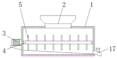
图1为本实用新型结构示意图;Fig. 1 is the structural representation of the utility model;
图2为本实用新型固定架结构俯视图;Fig. 2 is a top view of the utility model fixed frame structure;
图3为本实用新型机体结构剖视图。Fig. 3 is a sectional view of the body structure of the utility model.
图中:1、机体;2、进料斗;3、第一电机;4、连接轴;5、粉碎刀片;6、定位竖板;7、储尘箱;8、横板;9、吸尘泵;10、管套;11、吸尘罩;12、固定架;13、第二电机;14、螺纹杆;15、螺纹套;16、毛刷板;17、排料管。In the figure: 1. Body; 2. Feeding hopper; 3. First motor; 4. Connecting shaft; 5. Crushing blade; 6. Positioning vertical plate; 7. Dust storage box; 8. Horizontal plate; 9. Dust suction Pump; 10, pipe sleeve; 11, vacuum cover; 12, fixed frame; 13, second motor; 14, threaded rod; 15, threaded sleeve; 16, brush plate; 17, discharge pipe.
具体实施方式Detailed ways
下面将结合本实用新型实施例中的附图,对本实用新型实施例中的技术方案进行清楚、完整地描述,显然,所描述的实施例仅仅是本实用新型一部分实施例,而不是全部的实施例。基于本实用新型中的实施例,本领域普通技术人员在没有做出创造性劳动前提下所获得的所有其他实施例,都属于本实用新型保护的范围。The technical solutions in the embodiments of the present invention will be clearly and completely described below in conjunction with the accompanying drawings in the embodiments of the present invention. Obviously, the described embodiments are only part of the embodiments of the present invention, not all of them. example. Based on the embodiments of the present utility model, all other embodiments obtained by persons of ordinary skill in the art without making creative efforts belong to the scope of protection of the present utility model.
请参阅图1-3,本实用新型:一种农业秸秆回收装置,包括机体1,机体1的顶部连通有进料斗2,机体1左侧的底部通过支撑座固定安装有第一电机3,第一电机3的输出轴贯穿至机体1的内部固定安装有连接轴4,连接轴4的表面固定安装有粉碎刀片5,机体1两侧的顶部均通过螺栓固定安装有定位竖板6,定位竖板6的外侧设置有储尘箱7,两个定位竖板6之间的上方固定安装有横板8,横板8顶部的左侧卡接安装有吸尘泵9,吸尘泵9的出尘管与储尘箱7的左侧连通,吸尘泵9的进尘管贯穿至横板8的下方连通有吸尘罩11,定位竖板6内侧的下方固定安装有固定架12,固定架12内腔的右侧固定安装有第二电机13,第二电机13的输出轴固定安装有螺纹杆14,螺纹杆14的表面套接有螺纹套15,螺纹套15的顶部固定安装有毛刷板16,毛刷板16的顶部与吸尘罩11的底部相接触。Please refer to Figures 1-3, the utility model: an agricultural straw recovery device, including a
通过上述技术方案,通过在吸尘罩11的底部增加毛刷板16,在对灰尘进行吸收后底部附着的灰尘可通过毛刷板16进行清除,可防止吸尘罩11底部的滤网堵塞,能有效的对灰尘进行流畅吸收,该结构对滤网表面灰尘清除方便,且固定架12呈通槽式设计,不会阻碍灰尘的吸收,进而有效的提高在秸秆回收加工时对灰尘的吸收效率。Through the above technical scheme, by adding a
横板8的内部固定安装有管套10,吸尘泵9的进尘管一端贯穿管套10并活动连接。A
通过上述技术方案,通过管套10能对吸尘泵9进尘管的一端进行支撑限位,使其在贯穿横板8后使用较为稳定。Through the above technical solution, one end of the dust inlet pipe of the
机体1右侧的底部连通有排料管17,排料管17的表面活动安装有控制阀。The bottom of the right side of the
通过上述技术方案,通过在排料管17的表面增加控制阀,能对排出的流量进行控制。Through the above technical solution, by adding a control valve on the surface of the
储尘箱7的底部卡接安装有支撑板,且支撑板的右侧与定位竖板6的外侧固定安装。The bottom of the
通过上述技术方案,通过支撑板可对储尘箱7的底部进行支撑,并保证在定位竖板6侧面的稳定性。Through the above technical solution, the bottom of the
毛刷板16的顶部嵌设安装有刷毛,且刷毛的顶部与吸尘罩11底部的滤网相接触,毛刷板16的底部通过限位杆与固定架12的内壁滑动连接。The top of the
通过上述技术方案,刷毛与滤网的表面接触,能更好的对灰尘进行清除,可避免出现灰尘残留。Through the above technical proposal, the bristles are in contact with the surface of the filter screen, which can better remove dust and avoid dust residue.
本实用新型的工作原理是:将秸秆从进料斗2投入机体1的内部,启动第一电机3带动连接轴4与粉碎刀片5转动对秸秆进行粉碎加工,而产生的灰尘从进料斗2向上飘散,启动吸尘泵9带动吸尘罩11工作,并将灰尘全部吸收至储尘箱7的内部,随后启动第二电机13正反转动,并带动螺纹杆14转动,而螺纹杆14表面的螺纹套15在固定架12的内部左右缓慢移动,并同步带动上方的毛刷板16沿着吸尘罩11的下方左右移动对滤网表面附着的灰尘颗粒进行清扫,进而提高吸尘效率。The working principle of the utility model is: put the straw into the inside of the
最后应当说明的是,以上实施例仅用以说明本实用新型的技术方案,而非对本实用新型保护范围的限制,尽管参照较佳实施例对本实用新型作了详细地说明,本领域的普通技术人员应当理解,可以对本实用新型的技术方案进行修改或者等同替换,而不脱离本实用新型技术方案的实质和范围。Finally, it should be noted that the above embodiments are only used to illustrate the technical solutions of the present utility model, rather than limiting the protection scope of the present utility model. Although the utility model has been described in detail with reference to the preferred embodiments, those skilled in the art Personnel should understand that the technical solution of the utility model can be modified or equivalently replaced without departing from the essence and scope of the technical solution of the utility model.
Claims (5)
Priority Applications (1)
| Application Number | Priority Date | Filing Date | Title |
|---|---|---|---|
| CN202222268920.4U CN218417448U (en) | 2022-08-29 | 2022-08-29 | An agricultural straw recovery device |
Applications Claiming Priority (1)
| Application Number | Priority Date | Filing Date | Title |
|---|---|---|---|
| CN202222268920.4U CN218417448U (en) | 2022-08-29 | 2022-08-29 | An agricultural straw recovery device |
Publications (1)
| Publication Number | Publication Date |
|---|---|
| CN218417448U true CN218417448U (en) | 2023-02-03 |
Family
ID=85098127
Family Applications (1)
| Application Number | Title | Priority Date | Filing Date |
|---|---|---|---|
| CN202222268920.4U Expired - Fee Related CN218417448U (en) | 2022-08-29 | 2022-08-29 | An agricultural straw recovery device |
Country Status (1)
| Country | Link |
|---|---|
| CN (1) | CN218417448U (en) |
-
2022
- 2022-08-29 CN CN202222268920.4U patent/CN218417448U/en not_active Expired - Fee Related
Similar Documents
| Publication | Publication Date | Title |
|---|---|---|
| CN210901282U (en) | Multifunctional nut shell breaking machine | |
| CN208527312U (en) | Peanut vine crushes membrane removal dust removal machine | |
| CN119869933A (en) | Gravity separation impurity removing device for rape seeds | |
| CN210279760U (en) | Novel chinese herbal medicine sieve separator | |
| CN117206182B (en) | Fully enclosed oat cleaning machine and methods for cleaning oats | |
| CN213408976U (en) | Milling device suitable for feed processing | |
| CN213829246U (en) | Plant essential oil cutting additional device of dust absorption of can making an uproar falls | |
| CN2406743Y (en) | Huller for separating hulks from seeds | |
| CN213194461U (en) | Rice milling device with screening function | |
| CN211367598U (en) | Leather polishing device with dust collection mechanism | |
| CN218392933U (en) | Walking straw bundling machine | |
| CN219051642U (en) | a shredder | |
| CN218460407U (en) | Material guiding assembly of copper end vibrating screen of dry type copper rice machine | |
| CN222984517U (en) | Dust fall device for bran processing | |
| CN223011135U (en) | A rice shavings removing device for rice processing | |
| CN219352431U (en) | Dust-free straw crushing equipment | |
| CN217411506U (en) | Rice husk and rice separator | |
| CN221452708U (en) | Coarse cereal grinding device | |
| CN220741805U (en) | Dust removal equipment for PVC composite stabilizer production | |
| CN223786666U (en) | A seed threshing device for harvesting green beans | |
| CN112246305A (en) | Impurity-removing rice mill | |
| CN219073620U (en) | Novel wheat edulcoration machine | |
| CN221734089U (en) | Corn breeding sieving mechanism | |
| CN219441986U (en) | Impurity removing device for machine-made carbon raw materials | |
| CN220157101U (en) | Corn stalk processing and crushing device |
Legal Events
| Date | Code | Title | Description |
|---|---|---|---|
| GR01 | Patent grant | ||
| GR01 | Patent grant | ||
| CF01 | Termination of patent right due to non-payment of annual fee |
Granted publication date: 20230203 |