CN218415507U - A movable noise-reducing box-type substation - Google Patents
A movable noise-reducing box-type substation Download PDFInfo
- Publication number
- CN218415507U CN218415507U CN202221615805.3U CN202221615805U CN218415507U CN 218415507 U CN218415507 U CN 218415507U CN 202221615805 U CN202221615805 U CN 202221615805U CN 218415507 U CN218415507 U CN 218415507U
- Authority
- CN
- China
- Prior art keywords
- spring
- plate
- sliding
- fixedly connected
- support
- Prior art date
- Legal status (The legal status is an assumption and is not a legal conclusion. Google has not performed a legal analysis and makes no representation as to the accuracy of the status listed.)
- Active
Links
Images


Landscapes
- Vibration Prevention Devices (AREA)
Abstract
本实用新型公开了一种可移动降噪箱式变电站,包括缓冲组件,所述缓冲组件包括橡胶板、支撑板、第一弹簧、两个连接板、滑动柱、第二弹簧、两个连杆、拉簧、固定板、滑动套、两个限位环、四个支撑柱、支撑套筒、减震气囊和滑动杆;所述橡胶板的下表面固定连接于支撑板的上表面。本实用新型连接板通过第一弹簧对受到的力进行缓冲,滑动套通过第二弹簧对受到的力进行缓冲,通过拉簧可以限定滑动套的位移距离,进而可以防止变压器发生较大的晃动,支撑柱通过减震气囊对受到的力进行缓冲,通过将变压器振动产生的力进行缓冲,进而可以减小变压器工作时因振动而产生的噪音,避免了出现噪声污染的情况。
The utility model discloses a movable noise-reducing box-type substation, which comprises a buffer assembly, and the buffer assembly includes a rubber plate, a support plate, a first spring, two connecting plates, a sliding column, a second spring, and two connecting rods , extension spring, fixed plate, sliding sleeve, two limit rings, four supporting columns, supporting sleeve, shock absorbing air bag and sliding rod; the lower surface of the rubber plate is fixedly connected to the upper surface of the supporting plate. The connecting plate of the utility model buffers the force received by the first spring, and the sliding sleeve buffers the force received by the second spring, and the displacement distance of the sliding sleeve can be limited by the tension spring, thereby preventing the transformer from shaking greatly. The support column buffers the force received by the shock-absorbing air bag, and buffers the force generated by the transformer vibration, thereby reducing the noise generated by the vibration of the transformer during operation, and avoiding noise pollution.
Description
技术领域:Technical field:
本实用新型涉及箱式变电站技术领域,具体为一种可移动降噪箱式变电站。The utility model relates to the technical field of box-type substations, in particular to a movable noise-reducing box-type substation.
背景技术:Background technique:
箱式变电站,又叫预装式变电所或预装式变电站,是一种高压开关设备、配电变压器和低压配电装置,按一定接线方案排成一体的工厂预制户内、户外紧凑式配电设备,箱式变电站适用于住宅小区、城市公用变、繁华闹市、施工电源等。Box-type substation, also known as prefabricated substation or prefabricated substation, is a kind of high-voltage switchgear, distribution transformer and low-voltage power distribution device, which are prefabricated indoor and outdoor compact in a factory according to a certain wiring scheme. Power distribution equipment and box-type substations are suitable for residential quarters, urban public substations, bustling downtown areas, construction power supplies, etc.
由于箱式变电站内的变压器在工作时,磁致伸缩会引起铁芯振动、硅钢片接缝处和叠片之间漏磁会引起铁芯振动,因此变压器在振动时会产生比较大噪音,进而会对周围的环境造成噪声污染,为此,提出一种可移动降噪箱式变电站。When the transformer in the box-type substation is working, the magnetostriction will cause the iron core to vibrate, and the magnetic flux leakage between the joints of the silicon steel sheets and the laminations will cause the iron core to vibrate, so the transformer will generate relatively large noise when vibrating, and then It will cause noise pollution to the surrounding environment. Therefore, a movable noise-reducing box-type substation is proposed.
实用新型内容:Utility model content:
本实用新型的目的在于提供一种可移动降噪箱式变电站,以解决上述背景技术中提出的问题之一。The purpose of this utility model is to provide a movable noise-reducing box-type substation to solve one of the problems raised in the above-mentioned background technology.
本实用新型由如下技术方案实施:一种可移动降噪箱式变电站,包括缓冲组件,所述缓冲组件包括橡胶板、支撑板、第一弹簧、两个连接板、滑动柱、第二弹簧、两个连杆、拉簧、固定板、滑动套、两个限位环、四个支撑柱、支撑套筒、减震气囊和滑动杆;The utility model is implemented by the following technical solutions: a movable noise reduction box-type substation, including a buffer assembly, the buffer assembly includes a rubber plate, a support plate, a first spring, two connecting plates, a sliding column, a second spring, Two connecting rods, extension springs, fixed plates, sliding sleeves, two limit rings, four supporting columns, supporting sleeves, shock-absorbing airbags and sliding rods;
所述橡胶板的下表面固定连接于支撑板的上表面,两个所述连接板的相邻面对称焊接于支撑板的两侧,所述滑动柱滑动连接于连接板的内部,两个所述连杆的相邻面对称转动连接于滑动柱的两端,所述连杆的下表面转动连接于滑动套的外侧壁,所述滑动套的内侧壁滑动连接于滑动杆的外侧壁,所述滑动杆滑动连接于固定板的内部,所述第一弹簧套接于滑动柱的外侧壁,所述第二弹簧和拉簧均套接于滑动杆的外侧壁。The lower surface of the rubber plate is fixedly connected to the upper surface of the supporting plate, and the adjacent faces of the two connecting plates are symmetrically welded to both sides of the supporting plate, and the sliding column is slidably connected to the inside of the connecting plate. The adjacent faces of the connecting rod are symmetrically connected to both ends of the sliding column, the lower surface of the connecting rod is connected to the outer side wall of the sliding sleeve, and the inner side wall of the sliding sleeve is slidably connected to the outer side wall of the sliding rod. , the sliding rod is slidably connected to the inside of the fixing plate, the first spring is sleeved on the outer wall of the sliding column, and the second spring and the extension spring are both sleeved on the outer wall of the sliding rod.
作为本技术方案的进一步优选的:两个所述限位环对称焊接于滑动杆的两端,所述第二弹簧的一端固定连接于限位环的一侧,所述第二弹簧的另一端固定连接于滑动套的一侧,所述拉簧的一端固定连接于滑动套远离第二弹簧的一侧,所述拉簧的另一端固定连接于固定板的一侧,进而当连杆向下推动滑动套时,滑动套通过第二弹簧进行缓冲。As a further preference of this technical solution: the two limit rings are symmetrically welded to both ends of the sliding rod, one end of the second spring is fixedly connected to one side of the limit ring, and the other end of the second spring Fixedly connected to one side of the sliding sleeve, one end of the extension spring is fixedly connected to the side of the sliding sleeve away from the second spring, and the other end of the extension spring is fixedly connected to one side of the fixing plate, and then when the connecting rod is downward When the sliding sleeve is pushed, the sliding sleeve is buffered by the second spring.
作为本技术方案的进一步优选的:所述第一弹簧的一端固定连接于连杆的后表面,所述第一弹簧的另一端固定连接于连接板的前表面,四个所述支撑柱的上表面对称转动连接于支撑板的下表面,进而使连接板通过第一弹簧对受到的力进行缓冲。As a further preferred solution of this technical solution: one end of the first spring is fixedly connected to the rear surface of the connecting rod, the other end of the first spring is fixedly connected to the front surface of the connecting plate, and the upper ends of the four support columns The surface is symmetrically rotatably connected to the lower surface of the supporting plate, so that the connecting plate buffers the received force through the first spring.
作为本技术方案的进一步优选的:所述支撑柱的外侧壁滑动连接于支撑套筒的内侧壁,所述减震气囊安装于支撑套筒的内底壁,所述支撑柱的下表面贴合于减震气囊的上表面,进而可以使支撑柱通过减震气囊对受到的力进行缓冲减震。As a further preference of this technical solution: the outer wall of the support column is slidably connected to the inner wall of the support sleeve, the shock-absorbing airbag is installed on the inner bottom wall of the support sleeve, and the lower surface of the support column fits On the upper surface of the shock-absorbing airbag, the support column can buffer and absorb the received force through the shock-absorbing airbag.
作为本技术方案的进一步优选的:所述固定板的下表面安装有主体组件,所述主体组件包括变电站本体、透气孔、四个万向轮、吸音板、两个连接框和四个安装孔;As a further preference of this technical solution: the lower surface of the fixing plate is equipped with a main body assembly, the main body assembly includes a substation body, air holes, four universal wheels, sound-absorbing panels, two connection frames and four installation holes ;
所述固定板的下表面焊接于变电站本体的内底壁,所述支撑套筒的下表面转动连接于变电站本体的内底壁,进而可以将缓冲组件的位置固定,使整体结构更稳定。The lower surface of the fixing plate is welded to the inner bottom wall of the substation body, and the lower surface of the support sleeve is rotatably connected to the inner bottom wall of the substation body, thereby fixing the position of the buffer assembly and making the overall structure more stable.
作为本技术方案的进一步优选的:所述透气孔均匀开设于变电站本体的两侧,两个所述连接框的一侧对称固定连接于变电站本体的内壁两侧,进而可以通过透气孔可以进行散热。As a further preference of this technical solution: the vent holes are evenly opened on both sides of the substation body, and one side of the two connecting frames is symmetrically fixedly connected to both sides of the inner wall of the substation body, so that heat can be dissipated through the vent holes .
作为本技术方案的进一步优选的:所述吸音板的一侧固定连接于连接框远离变电站本体的一侧,所述吸音板与透气孔的位置相对应,四个所述安装孔对称开设于橡胶板的上表面,所述安装孔贯穿支撑板的下表面,通过吸音板可以避免变电站本体内的噪音通过透气孔传播到外部。As a further preferred solution of this technical solution: one side of the sound-absorbing board is fixedly connected to the side of the connection frame away from the substation body, the position of the sound-absorbing board corresponds to the air hole, and the four mounting holes are symmetrically opened in the rubber On the upper surface of the board, the installation hole runs through the lower surface of the supporting board, and the sound-absorbing board can prevent the noise in the substation body from being transmitted to the outside through the air vent.
作为本技术方案的进一步优选的:四个所述万向轮对称安装于变电站本体的下表面,进而可以通过万向轮推动变电站本体移动,在使用时更方便。As a further preferred aspect of this technical solution: the four universal wheels are symmetrically installed on the lower surface of the substation body, and the substation body can be pushed to move by the universal wheels, which is more convenient in use.
本实用新型的优点:本实用新型通过橡胶板可以对变压器进行初步减震,然后通过支撑板带动连接板,连接板通过第一弹簧对受到的力进行缓冲,连杆推动滑动套,滑动套通过第二弹簧对受到的力进行缓冲,通过拉簧可以限定滑动套的位移距离,进而可以防止变压器发生较大的晃动,支撑板推动支撑柱,支撑柱通过减震气囊对受到的力进行缓冲,通过对变压器振动产生的力进行缓冲,进而可以减小变压器工作时因振动而产生的噪音,避免了出现噪声污染的情况。Advantages of the utility model: the utility model can initially damp the transformer through the rubber plate, and then drive the connecting plate through the supporting plate, the connecting plate buffers the force received by the first spring, the connecting rod pushes the sliding sleeve, and the sliding sleeve passes through The second spring buffers the received force, and the displacement distance of the sliding sleeve can be limited by the tension spring, thereby preventing the transformer from swaying greatly. The support plate pushes the support column, and the support column buffers the received force through the shock-absorbing airbag. By buffering the force generated by the vibration of the transformer, the noise generated by the vibration during the operation of the transformer can be reduced, and noise pollution can be avoided.
附图说明:Description of drawings:
为了更清楚地说明本实用新型实施例或现有技术中的技术方案,下面将对实施例或现有技术描述中所需要使用的附图作简单地介绍,显而易见地,下面描述中的附图仅仅是本实用新型的一些实施例,对于本领域普通技术人员来讲,在不付出创造性劳动的前提下,还可以根据这些附图获得其他的附图。In order to more clearly illustrate the technical solutions in the embodiments of the present invention or the prior art, the following will briefly introduce the accompanying drawings that need to be used in the description of the embodiments or the prior art. Obviously, the accompanying drawings in the following description These are only some embodiments of the utility model, and those skilled in the art can also obtain other drawings based on these drawings without creative work.
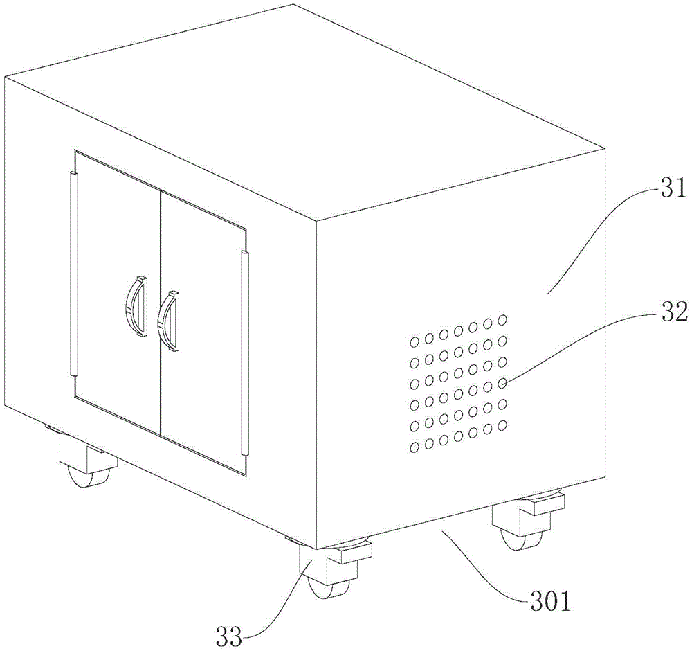
图1为本实用新型的结构示意图;Fig. 1 is the structural representation of the utility model;
图2为本实用新型的缓冲组件结构示意图;Fig. 2 is a structural schematic diagram of the buffer assembly of the present utility model;
图3为本实用新型的支撑柱结构示意图;Fig. 3 is a structural schematic diagram of a support column of the present invention;
图4为本实用新型的支撑套筒结构示意图;Fig. 4 is a structural schematic diagram of a support sleeve of the present invention;
图5为本实用新型的主体组件结构示意图。Fig. 5 is a structural schematic diagram of the main assembly of the present invention.
图中:101、缓冲组件;11、橡胶板;12、支撑板;13、第一弹簧;14、连接板;15、滑动柱;16、第二弹簧;17、连杆;18、拉簧;19、固定板;20、滑动套;21、限位环;22、支撑柱;23、支撑套筒;24、减震气囊;25、滑动杆;301、主体组件;31、变电站本体;32、透气孔;33、万向轮;34、吸音板;35、连接框;36、安装孔。In the figure: 101, buffer assembly; 11, rubber plate; 12, support plate; 13, first spring; 14, connecting plate; 15, sliding column; 16, second spring; 17, connecting rod; 18, extension spring; 19. Fixed plate; 20. Sliding sleeve; 21. Limiting ring; 22. Support column; 23. Support sleeve; 24. Damping airbag; 25. Slide rod; 301. Main component; Air vent; 33, universal wheel; 34, sound-absorbing panel; 35, connection frame; 36, installation hole.
具体实施方式:Detailed ways:
下面将结合本实用新型实施例中的附图,对本实用新型实施例中的技术方案进行清楚、完整地描述,显然,所描述的实施例仅仅是本实用新型一部分实施例,而不是全部的实施例。基于本实用新型中的实施例,本领域普通技术人员在没有做出创造性劳动前提下所获得的所有其他实施例,都属于本实用新型保护的范围。The technical solutions in the embodiments of the present invention will be clearly and completely described below in conjunction with the accompanying drawings in the embodiments of the present invention. Obviously, the described embodiments are only part of the embodiments of the present invention, not all of them. example. Based on the embodiments of the present utility model, all other embodiments obtained by persons of ordinary skill in the art without making creative efforts belong to the scope of protection of the present utility model.
实施例Example
请参阅图1-5,本实用新型提供一种技术方案:一种可移动降噪箱式变电站,包括缓冲组件101,缓冲组件101包括橡胶板11、支撑板12、第一弹簧13、两个连接板14、滑动柱15、第二弹簧16、两个连杆17、拉簧18、固定板19、滑动套20、两个限位环21、四个支撑柱22、支撑套筒23、减震气囊24和滑动杆25;Please refer to Figures 1-5, the utility model provides a technical solution: a movable noise reduction box-type substation, including a
橡胶板11的下表面固定连接于支撑板12的上表面,两个连接板14的相邻面对称焊接于支撑板12的两侧,滑动柱15滑动连接于连接板14的内部,两个连杆17的相邻面对称转动连接于滑动柱15的两端,连杆17的下表面转动连接于滑动套20的外侧壁,滑动套20的内侧壁滑动连接于滑动杆25的外侧壁,滑动杆25滑动连接于固定板19的内部,第一弹簧13套接于滑动柱15的外侧壁,第二弹簧16和拉簧18均套接于滑动杆25的外侧壁。The lower surface of the
本实施例中,具体的:两个限位环21对称焊接于滑动杆25的两端,第二弹簧16的一端固定连接于限位环21的一侧,第二弹簧16的另一端固定连接于滑动套20的一侧,拉簧18的一端固定连接于滑动套20远离第二弹簧16的一侧,拉簧18的另一端固定连接于固定板19的一侧,进而当连杆17向下推动滑动套20时,滑动套20通过第二弹簧16进行缓冲,同时拉簧18拉动滑动套20,可以减小滑动套20的位移距离,进而减小支撑板12的晃动幅度。In this embodiment, specifically: two
本实施例中,具体的:第一弹簧13的一端固定连接于连杆17的后表面,第一弹簧13的另一端固定连接于连接板14的前表面,四个支撑柱22的上表面对称转动连接于支撑板12的下表面,将变压器安装于橡胶板11的上方,工作时变压器振动并带动支撑板12晃动,支撑板12带动连接板14,进而使连接板14通过第一弹簧13对受到的力进行缓冲。In this embodiment, specifically: one end of the
本实施例中,具体的:支撑柱22的外侧壁滑动连接于支撑套筒23的内侧壁,减震气囊24安装于支撑套筒23的内底壁,支撑柱22的下表面贴合于减震气囊24的上表面,进而当支撑板12振动时,支撑板12带动支撑柱22,支撑柱22通过减震气囊24对受到的力进行缓冲减震,以减小支撑柱22的振动幅度。In this embodiment, specifically: the outer wall of the
本实施例中,具体的:固定板19的下表面安装有主体组件301,主体组件301包括变电站本体31、透气孔32、四个万向轮33、吸音板34、两个连接框35和四个安装孔36;In this embodiment, specifically: the lower surface of the
固定板19的下表面焊接于变电站本体31的内底壁,支撑套筒23的下表面转动连接于变电站本体31的内底壁,进而可以将缓冲组件101的位置固定,使整体结构更稳定。The lower surface of the
本实施例中,具体的:透气孔32均匀开设于变电站本体31的两侧,两个连接框35的一侧对称固定连接于变电站本体31的内壁两侧,当变压器在工作时会散发出热量,通过透气孔32可以进行散热。In this embodiment, specifically: the
本实施例中,具体的:吸音板34的一侧固定连接于连接框35远离变电站本体31的一侧,吸音板34与透气孔32的位置相对应,四个安装孔36对称开设于橡胶板11的上表面,安装孔36贯穿支撑板12的下表面,通过吸音板34可以避免变电站本体31内的噪音通过透气孔32传播到外部,同时不会影响透气孔32的透气功能。In this embodiment, specifically: one side of the sound-absorbing
本实施例中,具体的:四个万向轮33对称安装于变电站本体31的下表面,进而可以通过万向轮33推动变电站本体31移动,在使用时更方便。In this embodiment, specifically: four
工作原理或者结构原理,使用时,通过万向轮33可以方便变电站本体31的移动,在使用时可以将变压器通过安装孔36安装在橡胶板11上,变压器在工作时产生振动,通过橡胶板11可以进行初步减震,同时变压器通过橡胶板11带动支撑板12振动,支撑板12带动连接板14,连接板14沿着滑动柱15移动,进而此时可以通过第一弹簧13对连接板14受到的力进行缓冲,同时滑动柱15带动连杆17,连杆17推动滑动套20沿着滑动杆25滑动,滑动套20推动第二弹簧16,进而可以通过第二弹簧16对受到的力进行缓冲,同时拉簧18拉动滑动套20,通过拉簧18可以减小滑动套20的位移距离,以减小支撑板12的晃动幅度,进而减小变压器的晃动幅度,支撑板12向下压动支撑柱22,支撑柱22压动减震气囊24,进而可以通过减震气囊24进行缓冲,通过将变压器工作时振动产生的力进行缓冲,进而减小了变压器工作时因振动而产生的噪音,通过透气孔32可以将变压器工作时产生的热量排出,同时通过吸音板34可以避免噪声通过透气孔32释放至外部,以达到降噪的效果。Working principle or structural principle, when in use, the movement of the
以上所述仅为本实用新型的较佳实施例而已,并不用以限制本实用新型,凡在本实用新型的精神和原则之内,所作的任何修改、等同替换、改进等,均应包含在本实用新型的保护范围之内。The above descriptions are only preferred embodiments of the present utility model, and are not intended to limit the present utility model. Any modifications, equivalent replacements, improvements, etc. made within the spirit and principles of the present utility model shall be included in the Within the protection scope of the present utility model.
Claims (8)
Priority Applications (1)
| Application Number | Priority Date | Filing Date | Title |
|---|---|---|---|
| CN202221615805.3U CN218415507U (en) | 2022-06-24 | 2022-06-24 | A movable noise-reducing box-type substation |
Applications Claiming Priority (1)
| Application Number | Priority Date | Filing Date | Title |
|---|---|---|---|
| CN202221615805.3U CN218415507U (en) | 2022-06-24 | 2022-06-24 | A movable noise-reducing box-type substation |
Publications (1)
| Publication Number | Publication Date |
|---|---|
| CN218415507U true CN218415507U (en) | 2023-01-31 |
Family
ID=85009262
Family Applications (1)
| Application Number | Title | Priority Date | Filing Date |
|---|---|---|---|
| CN202221615805.3U Active CN218415507U (en) | 2022-06-24 | 2022-06-24 | A movable noise-reducing box-type substation |
Country Status (1)
| Country | Link |
|---|---|
| CN (1) | CN218415507U (en) |
-
2022
- 2022-06-24 CN CN202221615805.3U patent/CN218415507U/en active Active
Similar Documents
| Publication | Publication Date | Title |
|---|---|---|
| CN112727985B (en) | Hybrid bidirectional vibration damping support | |
| CN116142918A (en) | A combined rubber damping structure for elevator car | |
| CN107143614A (en) | Vibration damping device for construction equipment | |
| CN101781880B (en) | Sound absorbing-insulating barrier | |
| CN211501463U (en) | An anti-seismic connecting member for electromechanical equipment | |
| CN211018515U (en) | Motor shock attenuation mounting bracket | |
| CN214176574U (en) | Box-type substation equipment with buffer type base and used for protecting internal components | |
| CN211922338U (en) | Highway bridge pile foundation reinforcing apparatus | |
| CN210200523U (en) | Noise reduction structure of dry-type transformer | |
| CN216867411U (en) | Vibration isolation mounting device for building electrical equipment | |
| CN116667589A (en) | A motor shock-absorbing base | |
| CN213185201U (en) | Noise reduction device for transformer substation | |
| CN115497726A (en) | Transformer with shock and noise reduction device | |
| CN209483866U (en) | A kind of Architectural Equipment rubber vibration isolation device | |
| CN212516814U (en) | Anti-seismic base of dry-type power transformer | |
| JP3023624B2 (en) | Floating foundation strong vibration damper | |
| CN205601227U (en) | An anti-shock metal molding machine | |
| CN220651804U (en) | Noise reduction device for distribution transformer | |
| CN111082345B (en) | Block terminal that building site used and has buffer function | |
| CN222112578U (en) | Suspension type shock mitigation system | |
| CN218543032U (en) | Fixed knot constructs and three-dimensional viscous damper | |
| CN220032084U (en) | A six-wheel omnidirectional mobile robot | |
| CN205335049U (en) | Energy -conserving dry -type electrical transformer | |
| CN223814329U (en) | A vibration damping structure for a worm gear reducer | |
| CN221921801U (en) | Protection noise reduction device for soil remediation |
Legal Events
| Date | Code | Title | Description |
|---|---|---|---|
| GR01 | Patent grant | ||
| GR01 | Patent grant | ||
| PE01 | Entry into force of the registration of the contract for pledge of patent right |
Denomination of utility model: A movable noise reducing box type substation Granted publication date: 20230131 Pledgee: Inner Mongolia Bank Co.,Ltd. Hohhot Fengzhou Road Branch Pledgor: Zhongjingyun Construction Co.,Ltd. Registration number: Y2024980041471 |
|
| PE01 | Entry into force of the registration of the contract for pledge of patent right | ||
| PC01 | Cancellation of the registration of the contract for pledge of patent right |
Granted publication date: 20230131 Pledgee: Inner Mongolia Bank Co.,Ltd. Hohhot Fengzhou Road Branch Pledgor: Zhongjingyun Construction Co.,Ltd. Registration number: Y2024980041471 |
|
| PC01 | Cancellation of the registration of the contract for pledge of patent right | ||
| PE01 | Entry into force of the registration of the contract for pledge of patent right |
Denomination of utility model: A movable noise reducing box type substation Granted publication date: 20230131 Pledgee: Inner Mongolia Bank Co.,Ltd. Hohhot Fengzhou Road Branch Pledgor: Zhongjingyun Construction Co.,Ltd. Registration number: Y2025980022261 |
|
| PE01 | Entry into force of the registration of the contract for pledge of patent right |