CN218405106U - Box culvert structure for crossing flood drainage channel - Google Patents
Box culvert structure for crossing flood drainage channel Download PDFInfo
- Publication number
- CN218405106U CN218405106U CN202222210436.6U CN202222210436U CN218405106U CN 218405106 U CN218405106 U CN 218405106U CN 202222210436 U CN202222210436 U CN 202222210436U CN 218405106 U CN218405106 U CN 218405106U
- Authority
- CN
- China
- Prior art keywords
- box culvert
- outer end
- culvert
- end wall
- gravel
- Prior art date
- Legal status (The legal status is an assumption and is not a legal conclusion. Google has not performed a legal analysis and makes no representation as to the accuracy of the status listed.)
- Active
Links
Images


Landscapes
- Sewage (AREA)
Abstract
本实用新型公开了一种跨越排洪渠的箱涵结构,包括涵身和设在涵身底部的箱涵基础。箱涵顶板的内端、外部和外端一一对应地设置内端墙、外部端墙和外端墙,使箱涵的顶部被分隔成位于内端墙至外部端墙之间的道路部分和位于外部端墙至外端墙之间的绿化带;涵身的两侧均采用砂砾石充填;箱涵顶板的顶部铺筑道路结构层;两块箱涵侧墙的内端和外端均连接翼墙;两块箱涵侧墙的外端面上各自向外延伸一块洞口挡墙,两块洞口挡墙呈八字形布置;箱涵基础包括多根设有桩帽的管桩、填充在管桩的桩帽之间的砂砾石、铺设在管桩的桩帽顶上和砂砾石上且将两层土工格栅夹在当中的砂砾垫层以及铺设在砂砾垫层上的素混凝土层。本实用新型能减少不均匀沉降。
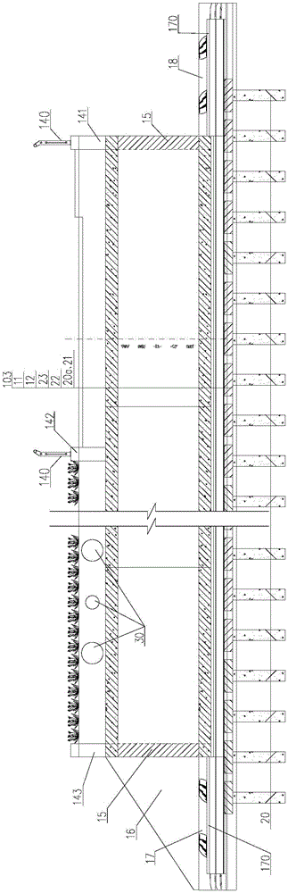
The utility model discloses a box culvert structure spanning a flood discharge channel, which comprises a culvert body and a box culvert foundation arranged at the bottom of the culvert body. The inner end, outer end and outer end of the top plate of the box culvert are provided with an inner end wall, an outer end wall and an outer end wall one by one, so that the top of the box culvert is divided into a road part between the inner end wall and the outer end wall and the The green belt between the outer end wall and the outer end wall; both sides of the culvert body are filled with sand and gravel; the top of the box culvert roof is paved with a road structure layer; the inner and outer ends of the two box culvert side walls are connected Wing wall; the outer end faces of the two box culvert side walls each extend a hole retaining wall outward, and the two hole retaining walls are arranged in a figure-eight shape; the box culvert foundation includes a number of pipe piles with pile caps, filled in pipe piles The gravel between the pile caps, the gravel cushion laid on the top of the pile cap of the pipe pile and the gravel with two layers of geogrid sandwiched in between, and the plain concrete layer laid on the gravel cushion. The utility model can reduce uneven settlement.
Description
技术领域technical field
本实用新型涉及一种跨越排洪渠的箱涵结构。The utility model relates to a box culvert structure spanning a flood discharge canal.
背景技术Background technique
在沿海边建设新产业园区的过程中,还需要建设服务于产业园区内区域交通的道路。在道路工程建设中会遇到跨越河流、渠道等问题,因此往往采用箱涵来跨越河渠。工程人员总是希望箱涵能够在保证结构强度的情况下,施工更方便,成本更低廉。箱涵分为明涵和暗涵两种结构型式,其中暗涵的构造简单,施工方便,受力性能好,为目前跨河渠的箱涵所采用的主流型式。当由于海边的地基基本为软土地基,因此箱涵在软土地基上建造时更要保证有足够的整体强度和稳定性,还要具有较高的可靠性和耐久性,保证在自然环境中,长期完好,不发生破损。另外目前的箱涵还存在顶部平整、无韵律变化、外形呆板等不足。In the process of building a new industrial park along the coast, it is also necessary to build roads serving regional traffic in the industrial park. Problems such as crossing rivers and canals may be encountered in road construction, so box culverts are often used to cross rivers and canals. Engineers always hope that the box culvert can be constructed more conveniently and at a lower cost while ensuring the structural strength. Box culverts are divided into two structural types: open culverts and hidden culverts. Among them, hidden culverts have simple structure, convenient construction, and good mechanical performance. They are currently the mainstream type of box culverts across rivers and canals. Since the foundation of the seaside is basically a soft soil foundation, when the box culvert is built on the soft soil foundation, it must ensure sufficient overall strength and stability, as well as high reliability and durability, so as to ensure that it can be used in the natural environment. , intact for a long time without damage. In addition, the current box culverts still have deficiencies such as smooth tops, no rhythmic changes, and rigid shapes.
实用新型内容Utility model content
本实用新型的目的在于克服现有技术的缺陷而提供一种跨越排洪渠的箱涵结构,它能有效减少涵身的不均匀沉降,并能美化箱涵。The purpose of the utility model is to overcome the defects of the prior art and provide a box culvert structure spanning the flood discharge channel, which can effectively reduce the uneven settlement of the culvert body and beautify the box culvert.
本实用新型的目的是这样实现的:一种跨越排洪渠的箱涵结构,包括外端洞口与外部水系连接、内端洞口与区域内部排水沟连接的涵身以及设在涵身底部的箱涵基础,所述涵身由箱涵顶板、箱涵底板和两块箱涵侧墙构成;其中,The purpose of this utility model is achieved in the following way: a box culvert structure spanning the flood discharge channel, including a culvert body connecting the outer hole with the external water system, the inner hole connected with the internal drainage ditch in the area, and the box at the bottom of the culvert. The culvert foundation, the culvert body is composed of a box culvert top plate, a box culvert bottom plate and two box culvert side walls; wherein,
所述箱涵顶板的内端、外部和外端一一对应地设置一面内端墙、外部端墙和外端墙,使箱涵的顶部被分隔成位于内端墙至外部端墙之间的道路部分和位于外部端墙至外端墙之间的绿化带;道路部分的内侧为人行道,其余部分为双向单车行道;The inner end, the outer end and the outer end of the box culvert roof are provided with an inner end wall, an outer end wall and an outer end wall one by one, so that the top of the box culvert is divided into an area between the inner end wall and the outer end wall. The road part and the green belt between the outer end wall and the outer end wall; the inner side of the road part is a sidewalk, and the rest is a two-way single-lane roadway;
所述涵身的两侧均采用砂砾石回填;所述箱涵顶板的顶部铺筑道路结构层;Both sides of the culvert body are backfilled with sand and gravel; the top of the box culvert roof is paved with a road structure layer;
两块箱涵侧墙的内端和外端均连接翼墙;两块箱涵侧墙的外端面上各自向外延伸一块洞口挡墙,两块洞口挡墙呈八字形布置,并在两块洞口挡墙之间的底部铺筑与箱涵底板的外端面连接的外端洞口底板;The inner and outer ends of the two box culvert side walls are connected to the wing wall; the outer end faces of the two box culvert side walls respectively extend outward a piece of opening retaining wall, and the two opening retaining walls are arranged in a figure-eight shape. The bottom between the opening retaining walls is paved with the outer end opening bottom plate connected to the outer end surface of the box culvert bottom plate;
所述箱涵底板的内端面上向前延伸内端洞口底板;The inner end surface of the bottom plate of the box culvert extends forward to the bottom plate of the inner hole;
所述箱涵基础包括多根设有桩帽的管桩、填充在管桩的桩帽之间的砂砾石、铺设在管桩的桩帽顶上和砂砾石上且将两层土工格栅夹在当中的砂砾垫层以及铺设在砂砾垫层上的素混凝土层。The box culvert foundation includes a plurality of pipe piles provided with pile caps, sand and gravel filled between the pile caps of the pipe piles, laid on the top of the pipe pile caps and sand and gravel, and sandwiching two layers of geogrids The gravel cushion and the plain concrete layer laid on the gravel cushion.
上述的跨越排洪渠的箱涵结构,其中,在对应双向单车行道的所述箱涵顶板的两侧的砂砾石的顶部各自通过砂砾垫层设置一块钢筋混凝土搭板,再在钢筋混凝土搭板上铺筑道路结构层。The above-mentioned box culvert structure across the flood discharge channel, wherein, a reinforced concrete slab is respectively arranged on the top of the gravel on both sides of the box culvert roof corresponding to the two-way single-vehicle roadway through a gravel cushion, and then a reinforced concrete slab is placed on the reinforced concrete slab. Pave the road structure layer above.
上述的跨越排洪渠的箱涵结构,其中,所述洞口挡墙的断面呈直角梯形,且洞口挡墙的厚度和高度自内而外逐渐减小。The above-mentioned box culvert structure spanning the flood discharge channel, wherein, the section of the opening retaining wall is a right-angled trapezoid, and the thickness and height of the opening retaining wall gradually decrease from inside to outside.
上述的跨越排洪渠的箱涵结构,其中,所述绿化带内预埋市政管道。The above-mentioned box culvert structure spanning the flood discharge channel, wherein, the municipal pipeline is pre-buried in the green belt.
上述的跨越排洪渠的箱涵结构,其中,所述内端墙的顶部和外部端墙的顶部均设置栏杆。In the above box culvert structure spanning the flood discharge channel, railings are provided on the top of the inner end wall and the top of the outer end wall.
上述的跨越排洪渠的箱涵结构,其中,多根所述管桩以矩形阵列布置,且纵向间距和横向间距均相同。In the above-mentioned box culvert structure spanning the flood discharge channel, a plurality of pipe piles are arranged in a rectangular array, and the vertical spacing and the horizontal spacing are the same.
本实用新型的跨越排洪渠的箱涵结构具有以下特点:The box culvert structure spanning the flood drainage canal of the utility model has the following characteristics:
1)通过设置满堂布置的管桩基础,能共同承担箱涵两侧回填的砂砾石的荷载及道路荷载,使箱涵的受力性能好,并通过在桩顶回填夹设了两层土工格栅的砂砾垫层,能有效减少涵身的不均匀沉降;1) By setting the pipe pile foundation arranged in the whole hall, it can jointly bear the load of sand and gravel backfilled on both sides of the box culvert and the road load, so that the mechanical performance of the box culvert is good. The gravel cushion of the grid can effectively reduce the uneven settlement of the culvert body;
2)在箱涵顶板的顶部通过设置一道外部端墙形成相互隔断的道路部分和绿化带,既保证了箱涵上行人的安全,又保证了车辆的正常行驶,还能在绿化带上铺设覆土层,种植一些树或花草,既可以净化空气,又能美化箱涵。2) An external end wall is set on the top of the box culvert to form a road section and a green belt that are separated from each other, which not only ensures the safety of pedestrians on the box culvert, but also ensures the normal driving of vehicles, and can also lay covering soil on the green belt Layers, planting some trees or flowers, can not only purify the air, but also beautify the box culvert.
附图说明Description of drawings
图1是本实用新型的跨越排洪渠的箱涵结构的平面图;Fig. 1 is the plane view of the box culvert structure across the flood discharge channel of the present utility model;
图2是本实用新型的跨越排洪渠的箱涵结构的立面图;Fig. 2 is the elevation view of the box culvert structure across the flood discharge channel of the present utility model;
图3是本实用新型的跨越排洪渠的箱涵结构的断面图;Fig. 3 is the sectional view of the box culvert structure across the flood discharge channel of the present utility model;
图4是本实用新型的跨越排洪渠的箱涵结构的内端洞口的断面图;Fig. 4 is the sectional view of the inner end opening of the box culvert structure across the flood discharge channel of the present utility model;
图5是本实用新型的跨越排洪渠的箱涵结构的外端洞口的断面图。Fig. 5 is a cross-sectional view of the outer end opening of the box culvert structure spanning the flood discharge channel of the present invention.
具体实施方式Detailed ways
下面将结合附图对本实用新型作进一步说明。The utility model will be further described below in conjunction with accompanying drawing.
请参阅图1至图5,本实用新型的跨越排洪渠的箱涵结构,包括外端洞口与外部水系连接、内端洞口与区域内部排水沟连接的涵身10以及设在涵身10底部的箱涵基础。Please refer to Fig. 1 to Fig. 5, the box culvert structure spanning the flood discharge channel of the present utility model includes the culvert body 10 connecting the outer hole with the external water system, the inner hole connected with the internal drainage ditch in the area, and the bottom of the culvert 10 The box culvert foundation.
涵身10呈矩形并由箱涵顶板11、箱涵底板12和两块箱涵侧墙13构成;箱涵顶板11的厚度、箱涵底板12的厚度和两块箱涵侧墙13的厚度均为45cm,涵身的断面的内部长度为4m,内部高度为3m;涵身10沿长度方向每隔10m设置一道沉降缝,每道沉降缝内均采用3cm厚的橡胶止水带填塞。The culvert body 10 is rectangular and consists of a box culvert top plate 11, a box
箱涵顶板11的内端、外部和外端一一对应地设置一面厚度均为50cm的内端墙141、外部端墙142和外端墙143,使箱涵的顶部被分隔成位于内端墙141至外部端墙142之间的道路部分和位于外部端墙142至外端墙143之间的绿化带,绿化带内还预埋市政管道30;道路部分的内侧为3m宽的人行道,其余部分为9m宽的双向单车行道。内端墙141的顶部和外部端墙142的顶部均设置栏杆140。The inner end, the outer end and the outer end of the box culvert top plate 11 are provided with an
涵身10的两侧均采用砂砾石100回填,砂砾石100采用水平分层对称地回填并采用振动压路机夯实,压实度为96%;自涵身10的底部向上2.9m的位置砂砾石100的横向回填范围为2.9m,2.9m向上至3.4m的位置砂砾石100的横向回填范围为6m,3.4m向上至3.9m的位置砂砾石100的横向回填范围为7m,使箱涵的台背呈台阶形,提高了台背的稳定性。Both sides of the culvert body 10 are backfilled with gravel 100, and the gravel 100 is backfilled symmetrically in horizontal layers and compacted with a vibratory roller, with a compaction degree of 96%; The horizontal backfill range of 2.9m, the horizontal backfill range of sand and gravel 100 from 2.9m up to 3.4m is 6m, and the horizontal backfill range of sand and gravel 100 from 3.4m up to 3.9m is 7m, so that the platform back of the box culvert It is stepped, which improves the stability of the stage back.
在对应双向单车行道的箱涵顶板11的两侧的砂砾石100的顶部各自通过15cm厚的砂砾垫层101设置一块宽度为5m、厚度为30cm的钢筋混凝土搭板102,再在钢筋混凝土搭板102上和其余部分的箱涵顶板11上铺筑道路结构层103;At the top of the gravel 100 on both sides of the box culvert top plate 11 corresponding to the two-way bicycle roadway, a reinforced
两块箱涵侧墙13的内端和外端均连接宽度为3m、厚度为0.5m的翼墙15,且两块箱涵侧墙13的外端面上各自向外延伸一块洞口挡墙16,两块洞口挡墙16呈八字形布置;洞口挡墙16的断面呈直角梯形,且洞口挡墙16的厚度和高度自内而外逐渐减小;The inner and outer ends of the two box
在两块洞口挡墙16之间的底部铺筑与箱涵底板12的外端面连接的且厚度为30cm的外端洞口底板17;外端洞口底板17的底部还铺设10cm厚的砂石垫层170。The bottom between the two opening
箱涵底板12的内端面上向前延伸5m长的且厚度为30cm的内端洞口底板18,内端洞口底板18的底部也铺设10cm厚的砂石垫层170。The inner end surface of the box
箱涵基础包括多根设有桩帽20a的管桩20、填充在管桩20的桩帽20a之间的砂砾石21、铺设在管桩20的桩帽20a顶上和砂砾石21上的砂砾垫层22以及铺设在砂砾垫层22上的素混凝土层23;管桩20的桩径为0.4m,桩帽20a的平面呈边长为120cm的正方形且桩帽20a的高度为30cm;多根管桩20以矩形阵列布置,且纵向间距和横向间距均为1.5m;素混凝土层23的厚度为10cm,素混凝土层23的宽度比涵身10的宽度大60cm,并且素混凝土层23的两侧一一对应地宽出涵身10的两侧30cm。砂砾垫层22的厚度为50cm,砂砾垫层22中夹设两层土工格栅;砂砾垫层22的宽度比素混凝土层23的宽度大4.2cm,并且砂砾垫层22的两侧一一对应地宽出素混凝土层23的两侧2.1m。The box culvert foundation includes a plurality of
本实用新型的跨越排洪渠的箱涵结构,采用满堂布置的管桩基础,能共同承担箱涵侧回填土料荷载及路面荷载,使箱涵的受力性能好,并通过下方的管桩基础传递至土层深处,避免了箱涵下方土层受压沉降。The box culvert structure of the utility model spanning the flood discharge channel adopts the pipe pile foundation arranged all over the hall, which can jointly bear the backfill soil material load on the side of the box culvert and the road surface load, so that the box culvert has good mechanical performance and passes through the pipe piles below. The foundation is transmitted to the depth of the soil layer, avoiding the settlement of the soil layer under the box culvert under pressure.
以上实施例仅供说明本实用新型之用,而非对本实用新型的限制,有关技术领域的技术人员,在不脱离本实用新型的精神和范围的情况下,还可以作出各种变换或变型,因此所有等同的技术方案也应该属于本实用新型的范畴,应由各权利要求所限定。The above embodiments are only for illustrating the utility model, rather than limiting the utility model. Those skilled in the art can also make various transformations or modifications without departing from the spirit and scope of the utility model. Therefore, all equivalent technical solutions should also belong to the category of the present utility model, and should be defined by each claim.
Claims (6)
Priority Applications (1)
| Application Number | Priority Date | Filing Date | Title |
|---|---|---|---|
| CN202222210436.6U CN218405106U (en) | 2022-08-19 | 2022-08-19 | Box culvert structure for crossing flood drainage channel |
Applications Claiming Priority (1)
| Application Number | Priority Date | Filing Date | Title |
|---|---|---|---|
| CN202222210436.6U CN218405106U (en) | 2022-08-19 | 2022-08-19 | Box culvert structure for crossing flood drainage channel |
Publications (1)
| Publication Number | Publication Date |
|---|---|
| CN218405106U true CN218405106U (en) | 2023-01-31 |
Family
ID=85027626
Family Applications (1)
| Application Number | Title | Priority Date | Filing Date |
|---|---|---|---|
| CN202222210436.6U Active CN218405106U (en) | 2022-08-19 | 2022-08-19 | Box culvert structure for crossing flood drainage channel |
Country Status (1)
| Country | Link |
|---|---|
| CN (1) | CN218405106U (en) |
Cited By (4)
| Publication number | Priority date | Publication date | Assignee | Title |
|---|---|---|---|---|
| CN116591073A (en) * | 2023-06-05 | 2023-08-15 | 武汉市市政建设集团有限公司 | An anti-seepage structure of a box culvert crossing an embankment and a construction method for an anti-seepage structure of a box culvert crossing an embankment |
| CN117107682A (en) * | 2023-10-11 | 2023-11-24 | 腾达建设集团股份有限公司 | Highway box culvert structure |
| CN117127447A (en) * | 2023-09-25 | 2023-11-28 | 广州市城市规划勘测设计研究院 | A transition structure between the box culvert and the road located in the soft foundation road section |
| CN117604935A (en) * | 2023-11-30 | 2024-02-27 | 中国市政工程中南设计研究总院有限公司 | Combined structure of wave-proof wall and drainage box culvert to reduce road filling height and its construction method |
-
2022
- 2022-08-19 CN CN202222210436.6U patent/CN218405106U/en active Active
Cited By (5)
| Publication number | Priority date | Publication date | Assignee | Title |
|---|---|---|---|---|
| CN116591073A (en) * | 2023-06-05 | 2023-08-15 | 武汉市市政建设集团有限公司 | An anti-seepage structure of a box culvert crossing an embankment and a construction method for an anti-seepage structure of a box culvert crossing an embankment |
| CN117127447A (en) * | 2023-09-25 | 2023-11-28 | 广州市城市规划勘测设计研究院 | A transition structure between the box culvert and the road located in the soft foundation road section |
| CN117107682A (en) * | 2023-10-11 | 2023-11-24 | 腾达建设集团股份有限公司 | Highway box culvert structure |
| CN117107682B (en) * | 2023-10-11 | 2026-04-03 | 腾达建设集团股份有限公司 | Highway box culvert structure |
| CN117604935A (en) * | 2023-11-30 | 2024-02-27 | 中国市政工程中南设计研究总院有限公司 | Combined structure of wave-proof wall and drainage box culvert to reduce road filling height and its construction method |
Similar Documents
| Publication | Publication Date | Title |
|---|---|---|
| CN103510441B (en) | Three-dimensional-drainage roadbed structure for preventing water damage of road in cold region and construction method thereof | |
| CN113445396B (en) | High-fill road foundation filling construction method for high liquid limit soil road section | |
| CN110438914B (en) | Water passing box culvert on soft soil foundation and construction method thereof | |
| CN203498721U (en) | Three-dimensional drainage roadbed structure preventing damage by water of road in cold region | |
| CN211199978U (en) | A permeable pavement pavement structure | |
| CN109826065B (en) | High-fill roadbed protection system and construction method thereof | |
| CN110258220B (en) | A method for ecologically filling road embankments with high-strength steel wire mesh reinforced materials | |
| CN110042723B (en) | Construction method of fully prefabricated permeable road | |
| CN105544342B (en) | A kind of urban road delay discharge structure based on porous pavement | |
| CN213086498U (en) | Assembled permeable base layer and permeable pavement paving structure | |
| CN110714479B (en) | Structure of water-permeable gravity retaining wall with embedded gravel column and construction method thereof | |
| CN113152628A (en) | V-shaped gully high-fill temporary drainage system and construction method thereof | |
| CN210288013U (en) | Interim drainage facility of central authorities' median convenient to construction | |
| CN108277715A (en) | Road pavement prefabricated component and paving structure for protecting ancient tree and laying method | |
| CN209178748U (en) | A kind of highway structure | |
| CN112854131B (en) | Ecological revetment in water source protection area and construction method thereof | |
| CN114703805A (en) | Combined seepage-proofing and sewage-intercepting system and method for adjusting plain reservoir | |
| CN219137282U (en) | A permeable and thermal insulation pavement structure for urban roads in seasonally frozen regions | |
| CN111749073A (en) | Water permeable reconstruction technology based on existing road base layer | |
| CN213772763U (en) | Prevent highway subgrade structure that subsides | |
| CN216838791U (en) | Roadbed and pavement structure located on pipeline facing dike | |
| CN214573096U (en) | Pavement paving structure with high water permeability | |
| CN214738582U (en) | A "V"-shaped gully high fill temporary drainage system | |
| CN209323289U (en) | A prefabricated green belt structure | |
| CN110424452B (en) | A backfilled ceramsite prefabricated reinforced retaining wall structure and construction method |
Legal Events
| Date | Code | Title | Description |
|---|---|---|---|
| GR01 | Patent grant | ||
| GR01 | Patent grant |