CN218396505U - Laser cutting device is used in ceramic substrate processing - Google Patents
Laser cutting device is used in ceramic substrate processing Download PDFInfo
- Publication number
- CN218396505U CN218396505U CN202222695235.XU CN202222695235U CN218396505U CN 218396505 U CN218396505 U CN 218396505U CN 202222695235 U CN202222695235 U CN 202222695235U CN 218396505 U CN218396505 U CN 218396505U
- Authority
- CN
- China
- Prior art keywords
- fixedly connected
- ceramic substrate
- plate
- shell
- wall
- Prior art date
- Legal status (The legal status is an assumption and is not a legal conclusion. Google has not performed a legal analysis and makes no representation as to the accuracy of the status listed.)
- Active
Links
- 239000000919 ceramic Substances 0.000 title claims abstract description 58
- 239000000758 substrate Substances 0.000 title claims abstract description 58
- 238000003698 laser cutting Methods 0.000 title claims abstract description 20
- 230000007246 mechanism Effects 0.000 claims abstract description 29
- 230000005540 biological transmission Effects 0.000 claims description 4
- 238000000034 method Methods 0.000 abstract description 6
- 230000008569 process Effects 0.000 abstract description 5
- 230000009286 beneficial effect Effects 0.000 abstract description 2
- 239000000463 material Substances 0.000 description 4
- 238000001125 extrusion Methods 0.000 description 3
- RYGMFSIKBFXOCR-UHFFFAOYSA-N Copper Chemical compound [Cu] RYGMFSIKBFXOCR-UHFFFAOYSA-N 0.000 description 1
- 230000004075 alteration Effects 0.000 description 1
- 239000011889 copper foil Substances 0.000 description 1
- PMHQVHHXPFUNSP-UHFFFAOYSA-M copper(1+);methylsulfanylmethane;bromide Chemical compound Br[Cu].CSC PMHQVHHXPFUNSP-UHFFFAOYSA-M 0.000 description 1
- 230000003993 interaction Effects 0.000 description 1
- 238000012986 modification Methods 0.000 description 1
- 230000004048 modification Effects 0.000 description 1
- TWNQGVIAIRXVLR-UHFFFAOYSA-N oxo(oxoalumanyloxy)alumane Chemical compound O=[Al]O[Al]=O TWNQGVIAIRXVLR-UHFFFAOYSA-N 0.000 description 1
- 238000003825 pressing Methods 0.000 description 1
- 230000001737 promoting effect Effects 0.000 description 1
- 238000006467 substitution reaction Methods 0.000 description 1
Images




Landscapes
- Laser Beam Processing (AREA)
Abstract
The utility model discloses a laser cutting device is used in processing of ceramic substrate, including the fixed station, the spout has been seted up on the inner wall of the back middle part of shell to the upper end fixedly connected with shell of fixed station, and the mid-mounting of spout has pushing equipment, installs cutting mechanism on the inner wall of the upper end middle part of shell, and the equal fixedly connected with fixed plate in lower extreme both sides of fixed station installs actuating mechanism jointly between two fixed plates, and the equal slip cap in both sides of fixed station is established and sliding connection has the movable plate, the beneficial effects of the utility model are that: the utility model discloses a set up a pushing equipment in the inside of shell, pushing equipment can be in the slip of shell, and the cutting mechanism on the unblock shell is to the ceramic substrate cutting on the fixed station, and when the ceramic substrate of taking, the slide that can pull pushing equipment slides on the diaphragm, and the push pedal through on the slide will promote ceramic substrate and slide on the fixed station, makes things convenient for the staff to take the ceramic substrate who cuts, and the process of taking is comparatively simple.
Description
Technical Field
The utility model relates to a ceramic substrate processing equipment technical field specifically is a laser cutting device is used in ceramic substrate processing.
Background
The ceramic substrate refers to a special process plate in which copper foil is directly bonded to the surface (single side or double sides) of an aluminum oxide or aluminum nitride ceramic substrate at high temperature. The laser cutting device is a basic material of a high-power electronic circuit structure technology and an interconnection technology, a ceramic substrate can be cut by using cutting equipment in the processing process, the ceramic substrate is convenient to store or perform other processing, and the laser cutting device is one of the equipment used in the cutting of the ceramic substrate.
At present ceramic substrate is put the workstation at laser cutting equipment most when the cutting and is got up fixedly by the centre gripping, but when taking off the ceramic substrate that the cutting is good, because ceramic substrate's lower extreme and laser cutting device's workstation mesa contact, need press the ceramic substrate upper surface with the hand, promote ceramic substrate's laser cutting device's workstation mesa and slide, take off ceramic substrate from laser cutting device, and ceramic substrate's surface is most comparatively smooth, the condition that skids appears easily when promoting ceramic substrate and slide on laser cutting device for the staff, the process that leads to taking ceramic substrate is comparatively troublesome.
SUMMERY OF THE UTILITY MODEL
An object of the utility model is to provide a laser cutting device is used in processing of ceramic substrate to solve the problem that proposes in the above-mentioned background art.
In order to achieve the above purpose, the utility model provides a following technical scheme: a laser cutting device for processing a ceramic substrate comprises a fixed table, wherein the upper end of the fixed table is fixedly connected with a shell, a chute is formed in the inner wall of the middle of the back surface of the shell, a material pushing mechanism is installed in the middle of the chute, a cutting mechanism is installed on the inner wall of the middle of the upper end of the shell, fixed plates are fixedly connected to two sides of the lower end of the fixed table, a driving mechanism is jointly installed between the two fixed plates, movable plates are slidably sleeved on two sides of the fixed table and are slidably connected with the two movable plates, the two movable plates are both of a U-shaped structure, threaded plates are fixedly connected to the outer walls of the lower ends of the two movable plates, close to the middle of the fixed table, on one sides of the lower ends of the two movable plates, close to the middle of the fixed table, and clamping plates are fixedly connected to one sides of the upper ends of the two movable plates, close to the middle of the fixed table;
the pushing mechanism comprises a transverse plate, a sliding block is fixedly connected to the back of the transverse plate, the sliding block is connected to the inside of the sliding groove in a sliding mode, a sliding strip is connected to the inside of the transverse plate in a sliding mode, a sliding plate is fixedly connected to the lower end of the sliding strip, a push plate is fixedly connected to the back of the lower end of the sliding plate, and a pull rod is fixedly connected to the front of the lower end of the sliding plate;
cutting mechanism includes the mounting panel, mounting panel fixed connection is on the upper end inner wall of shell, fixedly connected with motor on the positive outer wall of mounting panel, the first screw rod of fixedly connected with on the output of motor, the one end that the motor was kept away from to first screw rod passes the positive lateral wall of mounting panel and rotates and connect on the back inner wall of mounting panel, the middle part cover of first screw rod is established and threaded connection has the thread piece, the lower extreme fixedly connected with laser head of thread piece.
Preferably, two splint all are L shape structure and the horizontal part lower extreme all through fixed spring fixedly connected with stripper plate, two the equal sliding connection of stripper plate is in the vertical part of homonymy splint.
Preferably, actuating mechanism includes the second screw rod, the both ends of second screw rod are all rotated and are connected on homonymy fixed plate, the second screw rod runs through and threaded connection is on two thread plates, the middle part cover of second screw rod is established and the first wheel body of fixedly connected with, first wheel body is connected with the second wheel body through drive belt transmission, the both sides of second wheel body all rotate through the pivot and are connected with the hanger plate, the lower extreme at the fixed station is all fixed to the hanger plate, the equal fixedly connected with runner of pivot tip of second wheel body.
Preferably, the transverse plates are longitudinally arranged, the distance between the upper ends and the lower ends of the transverse plates is larger than the distance between the upper ends and the lower ends of the sliding grooves, and the back surfaces of the transverse plates abut against the inner wall of the back surface of the shell.
Preferably, the inner wall of the moving plate supports against the fixed table, and the upper end of the moving plate penetrates through and is connected to the side wall of the shell in a sliding mode.
Compared with the prior art, the beneficial effects of the utility model are that: the utility model discloses a set up a pushing equipment in the inside of shell, pushing equipment can be in the slip of shell, and the cutting mechanism on the unblock shell is to the ceramic substrate cutting on the fixed station, and when the ceramic substrate of taking, the slide that can pull pushing equipment slides on the diaphragm, and the push pedal through on the slide will promote ceramic substrate and slide on the fixed station, makes things convenient for the staff to take the ceramic substrate who cuts, and the process of taking is comparatively simple.
Drawings
FIG. 1 is a schematic sectional view of the present invention;
FIG. 2 is a schematic view of the pushing mechanism of the present invention;
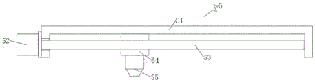
FIG. 3 is a schematic structural view of the cutting mechanism of the present invention;
fig. 4 is a schematic structural view of the driving mechanism of the present invention;
fig. 5 is an external schematic view of the present invention.
In the figure: 1. a fixed table; 2. a housing; 3. a chute; 4. a material pushing mechanism; 41. a transverse plate; 42. a slider; 43. a slide bar; 44. a slide plate; 45. pushing the plate; 46. a pull rod; 5. a cutting mechanism; 51. mounting a plate; 52. a motor; 53. a first screw; 54. a thread block; 55. a laser head; 6. a fixing plate; 7. moving the plate; 8. a thread plate; 9. a drive mechanism; 91. a second screw; 92. a first wheel body; 93. a transmission belt; 94. a second wheel body; 95. a hanger plate; 96. a rotating wheel; 10. a splint; 11. fixing the spring; 12. and (5) pressing the plate.
Detailed Description
The technical solutions in the embodiments of the present invention will be described clearly and completely with reference to the accompanying drawings in the embodiments of the present invention, and it is obvious that the described embodiments are only some embodiments of the present invention, not all embodiments. Based on the embodiments in the present invention, all other embodiments obtained by a person skilled in the art without creative work belong to the protection scope of the present invention.
Referring to fig. 1-5, the present invention provides a technical solution: a laser cutting device for processing a ceramic substrate comprises a fixed table 1, wherein the upper end of the fixed table 1 is fixedly connected with a shell 2, the inner wall of the middle of the back surface of the shell 2 is provided with a chute 3, the middle of the chute 3 is provided with a material pushing mechanism 4, the inner wall of the middle of the upper end of the shell 2 is provided with a cutting mechanism 5, two sides of the lower end of the fixed table 1 are fixedly connected with fixed plates 6, a driving mechanism 9 is jointly arranged between the two fixed plates 6, two sides of the fixed table 1 are slidably sleeved and connected with movable plates 7, the two movable plates 7 are both of a U-shaped structure, the outer wall of one side, close to the middle of the fixed table 1, of the lower ends of the two movable plates 7 is fixedly connected with threaded plates 8, one side, close to the middle of the fixed table 1, of the upper ends of the two movable plates 7 is fixedly connected with a clamping plate 10, and when the laser cutting device is used, the ceramic substrate can be clamped on the fixed table 1; the pushing mechanism 4 comprises a transverse plate 41, a sliding block 42 is fixedly connected to the back of the transverse plate 41, the sliding block 42 is connected to the inside of the sliding groove 3 in a sliding mode, a sliding strip 43 is connected to the inside of the transverse plate 41 in a sliding mode, a sliding plate 44 is fixedly connected to the lower end of the sliding strip 43, a pushing plate 45 is fixedly connected to the back of the lower end of the sliding plate 44, a pull rod 46 is fixedly connected to the front of the lower end of the sliding plate 44, and when the pushing mechanism is used, a ceramic substrate can be pushed to slide on the fixing table 1, and the ceramic substrate is convenient to take; cutting mechanism 5 includes mounting panel 51, mounting panel 51 fixed connection is on the upper end inner wall of shell 2, fixedly connected with motor 52 on mounting panel 51's the front outer wall, first screw rod 53 of fixedly connected with on the output of motor 52, the one end that motor 52 was kept away from to first screw rod 53 passes mounting panel 51's front lateral wall and rotates and connect on mounting panel 51's back inner wall, the middle part cover of first screw rod 53 is established and threaded connection has thread block 54, thread block 54's lower extreme fixedly connected with laser head 55, can be used to cut ceramic substrate.
Specifically, use the utility model discloses the time, switch on, the ceramic substrate who will wait to cut is put in fixed station 1 upper end, rotate second wheel body 94 through runner 96, second wheel body 94 drives first wheel body 92 through drive belt 93 and rotates, first wheel body 92 drives second screw rod 91 and rotates, second screw rod 91 drives two thread plates 8 and drives two movable plates 7 and move in opposite directions on fixed station 1, press from both sides two splint 10 at the ceramic substrate, the both sides of ceramic substrate can jack up homonymy stripper plate 12 simultaneously, and two stripper plates 12 support on ceramic substrate in the extrusion of homonymy fixed spring 11, fix ceramic substrate in the upper end middle part of fixed station 1, slide diaphragm 41 to inside one side of shell 2, and close shell 2, through control structure driving motor 52 and laser head 55, motor 52 drives first screw rod 53 and rotates, first screw rod 53 drives thread block 54 and drives laser head 55 and moves in the ceramic substrate top, this in-process laser head 55 cuts the ceramic substrate of below, after the cutting, can open shell 2, and slide the slide diaphragm 41 to the top of cutting, the ceramic substrate top of slide, the worker can pull the ceramic substrate through ceramic substrate fixing station upper end of ceramic substrate 46, then the fixed station can be pulled from ceramic substrate 1 after the ceramic substrate fixing station 1, the pull rod 44 can be held by another ceramic substrate, the ceramic substrate fixing station, the worker can be reached the pull-on the fixed station 1, the pull rod after the pull rod 46, the ceramic substrate, the pull rod can be reached the ceramic substrate.
In the description of the present invention, it is to be understood that the terms "coaxial", "bottom", "one end", "top", "middle", "other end", "upper", "one side", "top", "inner", "front", "center", "both ends", and the like, indicate orientations or positional relationships based on the orientations or positional relationships shown in the drawings, and are only for convenience of description and simplicity of description, and do not indicate or imply that the device or element referred to must have a particular orientation, be constructed and operated in a particular orientation, and therefore, should not be construed as limiting the present invention.
Furthermore, the terms "first", "second", "third", "fourth" are used for descriptive purposes only and are not to be construed as indicating or implying a relative importance or implicitly indicating the number of technical features indicated, whereby the features defined as "first", "second", "third", "fourth" may explicitly or implicitly include at least one such feature.
In the present invention, unless otherwise explicitly specified or limited, the terms "mounted", "disposed", "connected", "fixed", "screwed" and the like are to be understood broadly, and may be, for example, a fixed connection, a detachable connection, or an integral body; can be mechanically or electrically connected; they may be directly connected or indirectly connected through an intermediate medium, and may be connected through the inside of two elements or in an interaction relationship between two elements, unless otherwise specifically defined, and the specific meaning of the above terms in the present invention will be understood by those skilled in the art according to specific situations.
Although embodiments of the present invention have been shown and described, it will be appreciated by those skilled in the art that various changes, modifications, substitutions and alterations can be made in these embodiments without departing from the principles and spirit of the invention, the scope of which is defined in the appended claims and their equivalents.
Claims (5)
1. The laser cutting device for processing the ceramic substrate is characterized by comprising a fixed table (1), wherein the upper end of the fixed table (1) is fixedly connected with a shell (2), a sliding groove (3) is formed in the inner wall of the middle of the back surface of the shell (2), a pushing mechanism (4) is installed in the middle of the sliding groove (3), a cutting mechanism (5) is installed on the inner wall of the middle of the upper end of the shell (2), fixed plates (6) are fixedly connected to two sides of the lower end of the fixed table (1), a driving mechanism (9) is installed between the two fixed plates (6) together, movable plates (7) are slidably sleeved and slidably connected to two sides of the fixed table (1), the two movable plates (7) are both in a U-shaped structure, threaded plates (8) are fixedly connected to the outer wall of one side, close to the middle of the fixed table (1), of the lower ends of the two movable plates (7), and clamping plates (10) are fixedly connected to one side, close to the middle of the fixed table (1), of the upper ends of the two movable plates (7);
the pushing mechanism (4) comprises a transverse plate (41), a sliding block (42) is fixedly connected to the back surface of the transverse plate (41), the sliding block (42) is connected to the inside of the sliding groove (3) in a sliding mode, a sliding strip (43) is connected to the inside of the transverse plate (41) in a sliding mode, a sliding plate (44) is fixedly connected to the lower end of the sliding strip (43), a pushing plate (45) is fixedly connected to the back surface of the lower end of the sliding plate (44), and a pull rod (46) is fixedly connected to the front surface of the lower end of the sliding plate (44);
cutting mechanism (5) includes mounting panel (51), mounting panel (51) fixed connection is on the upper end inner wall of shell (2), fixedly connected with motor (52) on the front outer wall of mounting panel (51), first screw rod (53) of fixedly connected with on the output of motor (52), the one end that motor (52) were kept away from in first screw rod (53) is passed the front lateral wall of mounting panel (51) and is rotated and connect on the back inner wall of mounting panel (51), the middle part cover of first screw rod (53) is established and threaded connection has thread block (54), the lower extreme fixedly connected with laser head (55) of thread block (54).
2. The laser cutting apparatus for processing a ceramic substrate according to claim 1, wherein: two splint (10) all are L shape structure and horizontal part lower extreme all through fixed spring (11) fixedly connected with stripper plate (12), two the equal sliding connection in vertical part of homonymy splint (10) of stripper plate (12).
3. The laser cutting apparatus for processing a ceramic substrate according to claim 1, wherein: actuating mechanism (9) include second screw rod (91), the both ends of second screw rod (91) are all rotated and are connected on homonymy fixed plate (6), second screw rod (91) run through and threaded connection is on two thread plates (8), the first wheel body (92) of fixedly connected with is established to the middle part cover of second screw rod (91), first wheel body (92) are connected with second wheel body (94) through drive belt (93) transmission, the both sides of second wheel body (94) all are connected with hanger plate (95) through the pivot rotation, the lower extreme in fixed station (1) is all fixed in hanger plate (95), the equal fixedly connected with runner (96) of the pivot tip of second wheel body (94).
4. The laser cutting device for ceramic substrate processing according to claim 1, wherein: the transverse plate (41) is arranged longitudinally, the distance between the upper end and the lower end of the transverse plate (41) is larger than the distance between the upper end and the lower end of the sliding groove (3), and the back surface of the transverse plate (41) is abutted to the inner wall of the back surface of the shell (2).
5. The laser cutting device for ceramic substrate processing according to claim 1, wherein: the inner wall of the moving plate (7) is abutted to the fixed table (1), and the upper end of the moving plate (7) penetrates through the side wall of the shell (2) and is connected to the side wall in a sliding mode.
Priority Applications (1)
| Application Number | Priority Date | Filing Date | Title |
|---|---|---|---|
| CN202222695235.XU CN218396505U (en) | 2022-10-13 | 2022-10-13 | Laser cutting device is used in ceramic substrate processing |
Applications Claiming Priority (1)
| Application Number | Priority Date | Filing Date | Title |
|---|---|---|---|
| CN202222695235.XU CN218396505U (en) | 2022-10-13 | 2022-10-13 | Laser cutting device is used in ceramic substrate processing |
Publications (1)
| Publication Number | Publication Date |
|---|---|
| CN218396505U true CN218396505U (en) | 2023-01-31 |
Family
ID=85001022
Family Applications (1)
| Application Number | Title | Priority Date | Filing Date |
|---|---|---|---|
| CN202222695235.XU Active CN218396505U (en) | 2022-10-13 | 2022-10-13 | Laser cutting device is used in ceramic substrate processing |
Country Status (1)
| Country | Link |
|---|---|
| CN (1) | CN218396505U (en) |
-
2022
- 2022-10-13 CN CN202222695235.XU patent/CN218396505U/en active Active
Similar Documents
| Publication | Publication Date | Title |
|---|---|---|
| CN219275985U (en) | Cutting device | |
| CN214025940U (en) | Cutting device is used in integrated circuit board production | |
| CN218837935U (en) | A continuous punching device for battery insulating sheet | |
| CN219395333U (en) | Positioning and clamping device | |
| CN214394352U (en) | Hot slip film cutting adjustment mechanism | |
| CN214818821U (en) | Battery package blue membrane shearing mechanism | |
| CN210475747U (en) | Aluminum profile processing equipment | |
| CN217452336U (en) | A double-knife type aluminum profile dust-free cutting device | |
| CN215934325U (en) | Electrician is with portable wire device of skinning | |
| CN211729430U (en) | Hot melt adhesive film forming device | |
| CN215009327U (en) | Double-end coaxial line stripping off device | |
| CN213195420U (en) | High-temperature superconducting wire shearing device convenient to fix | |
| CN212397937U (en) | Cutting device is used in car wiring harness production and processing | |
| CN210436215U (en) | Cutting device is used in storage battery cover production | |
| CN216236680U (en) | A cutting machine for glass processing that is convenient for clamping workpieces | |
| CN217292918U (en) | Clamping and fixing device of semiconductor single crystal silicon rod cutting machine | |
| CN218534193U (en) | Fan-shaped rectangular thickness processing equipment | |
| CN222944402U (en) | New energy automobile wire cutting device | |
| CN217192913U (en) | Battery section device with locate function | |
| CN223560021U (en) | Cutting machine pushing device with heating edge sealing structure | |
| CN217097925U (en) | Cutting device is used in processing of LED filament base plate | |
| CN223669884U (en) | Battery shell breaking device | |
| CN213857140U (en) | Perforating device for metalworking | |
| CN217751612U (en) | Reciprocating type cutter for cutting sheet | |
| CN220177364U (en) | Dispensing mechanism for semiconductor chip production |
Legal Events
| Date | Code | Title | Description |
|---|---|---|---|
| GR01 | Patent grant | ||
| GR01 | Patent grant |