CN218379274U - Line lamp convenient to installation - Google Patents
Line lamp convenient to installation Download PDFInfo
- Publication number
- CN218379274U CN218379274U CN202222319761.6U CN202222319761U CN218379274U CN 218379274 U CN218379274 U CN 218379274U CN 202222319761 U CN202222319761 U CN 202222319761U CN 218379274 U CN218379274 U CN 218379274U
- Authority
- CN
- China
- Prior art keywords
- lampshade
- wall
- fixedly connected
- top surface
- easy
- Prior art date
- Legal status (The legal status is an assumption and is not a legal conclusion. Google has not performed a legal analysis and makes no representation as to the accuracy of the status listed.)
- Expired - Fee Related
Links
Images


Landscapes
- Fastening Of Light Sources Or Lamp Holders (AREA)
- Non-Portable Lighting Devices Or Systems Thereof (AREA)
Abstract
本实用新型涉及线条灯技术领域,公开了一种便于安装的线条灯,包括固定板,所述固定板的顶面中部固定连接在安装座的底面,所述安装座的顶面固定连接有LED灯泡,所述固定板的顶面固定连接有固定环,所述固定环的外侧螺纹连接在灯罩内壁的底部,所述灯罩内壁顶面的中部两侧均固定连接有卡杆,两个所述卡杆相远离一面的底部设置在固定环的内壁中部,所述灯罩的外壁底部固定连接有防滑块。本实用新型中,通过旋转灯罩可将其取下,可对LED灯泡维修,通过将灯罩重新拧紧在和固定环的外侧,使卡杆卡进固定环内壁螺纹的缝隙中,可使灯罩固定在固定环上,使灯罩的拆装极为便利,便于后期对LED灯泡的维修与更换。

The utility model relates to the technical field of line lights, and discloses a line light that is easy to install, comprising a fixing plate, the middle part of the top surface of the fixing plate is fixedly connected to the bottom surface of a mounting base, and the top surface of the mounting base is fixedly connected with an LED As for the light bulb, the top surface of the fixed plate is fixedly connected with a fixed ring, and the outer side of the fixed ring is threadedly connected to the bottom of the inner wall of the lampshade, and both sides of the middle part of the top surface of the inner wall of the lampshade are fixedly connected with clamping rods. The bottom of the side away from the clamping rod is arranged in the middle of the inner wall of the fixing ring, and the bottom of the outer wall of the lampshade is fixedly connected with an anti-slip block. In the utility model, the lampshade can be removed by rotating the lampshade, and the LED bulb can be repaired. By re-tightening the lampshade on the outside of the fixing ring, the clamping rod can be inserted into the gap of the thread on the inner wall of the fixing ring, so that the lampshade can be fixed on the On the fixing ring, it is very convenient to disassemble and assemble the lampshade, which is convenient for the maintenance and replacement of the LED bulb in the later stage.
Description
技术领域technical field
本实用新型涉及线条灯技术领域,尤其涉及一种便于安装的线条灯。The utility model relates to the technical field of linear lamps, in particular to a linear lamp which is easy to install.
背景技术Background technique
线条灯是用若干个LED灯泡组成,利用LED灯泡作为发光单元,使其线性排列,从而形成线条灯,可用于对物体的轮廓起到照明的作用,同时也可进行警示的作用,是现在装饰城市环境的理想选择,而传统的线条灯设计复杂,在LED灯泡发生损坏需要维修时,不易拆卸,且临时使用线条灯时,挂设不便,不便工作人员操作。The line light is composed of several LED bulbs, and the LED bulbs are used as the light-emitting unit to make them linearly arranged to form a line light, which can be used to illuminate the outline of objects, and can also be used as a warning. It is now a decorative The ideal choice for urban environments, while the traditional linear light has a complex design, and it is not easy to disassemble when the LED bulb is damaged and needs to be repaired. When the linear light is used temporarily, it is inconvenient to hang and inconvenient for the staff to operate.
实用新型内容Utility model content
本实用新型的目的是为了解决现有技术中存在的缺点,而提出的一种便于安装的线条灯。The purpose of the utility model is to solve the shortcomings in the prior art, and propose a line light that is easy to install.
为了实现上述目的,本实用新型采用了如下技术方案:一种便于安装的线条灯,包括固定板,所述固定板的顶面中部固定连接在安装座的底面,所述安装座的顶面固定连接有LED灯泡,所述固定板的顶面固定连接有固定环,所述固定环的外侧螺纹连接在灯罩内壁的底部,所述灯罩内壁顶面的中部两侧均固定连接有卡杆,两个所述卡杆相远离一面的底部设置在固定环的内壁中部,所述灯罩的外壁底部固定连接有防滑块。In order to achieve the above object, the utility model adopts the following technical scheme: a line light that is easy to install, including a fixing plate, the middle part of the top surface of the fixing plate is fixedly connected to the bottom surface of the mounting base, and the top surface of the mounting base is fixed LED light bulbs are connected, the top surface of the fixed plate is fixedly connected with a fixed ring, the outer thread of the fixed ring is connected to the bottom of the inner wall of the lampshade, and both sides of the middle part of the top surface of the inner wall of the lampshade are fixedly connected with clamping rods. The bottoms of the two clamping rods on the side away from each other are arranged in the middle part of the inner wall of the fixing ring, and the bottom of the outer wall of the lampshade is fixedly connected with an anti-slip block.
作为上述技术方案的进一步描述:As a further description of the above technical solution:
所述防滑块有若干个,若干个所述防滑块均匀分布在灯罩外壁的底部。There are several anti-slip blocks, and the several anti-slip blocks are evenly distributed on the bottom of the outer wall of the lampshade.
作为上述技术方案的进一步描述:As a further description of the above technical solution:
所述固定环的内壁中部与外壁中部均设置有螺纹,所述固定环外壁的螺纹与所述灯罩内壁的底部螺纹连接。Both the middle part of the inner wall and the middle part of the outer wall of the fixing ring are provided with threads, and the threads of the outer wall of the fixing ring are threadedly connected with the bottom of the inner wall of the lampshade.
作为上述技术方案的进一步描述:As a further description of the above technical solution:
两个所述卡杆相远离一侧的底部分别与所述固定环内壁螺纹的两侧连接。The bottoms of the two clamping rods on one side away from each other are respectively connected to the two sides of the thread on the inner wall of the fixing ring.
作为上述技术方案的进一步描述:As a further description of the above technical solution:
所述固定板的两侧均设置有固定槽,两个所述固定槽的内部均设置有导线,且两个所述导线均与LED灯泡电性连接。Both sides of the fixing plate are provided with fixing grooves, and wires are arranged inside the two fixing grooves, and both wires are electrically connected to the LED light bulb.
作为上述技术方案的进一步描述:As a further description of the above technical solution:
所述灯罩的底部固定连接有橡胶圈。The bottom of the lampshade is fixedly connected with a rubber ring.
作为上述技术方案的进一步描述:As a further description of the above technical solution:
所述固定板底面的中部固定连接在支柱的顶部,所述支柱的底部转动连接在夹板的顶面中部,所述固定板的底面和所述夹板的顶面之间设置有安装板,所述安装板的顶面与所述固定板的底面接触,所述安装板的底面与所述安装板的顶面接触,所述安装板底面的中部两侧固定均转动连接有安装柱,两个所述安装柱的底部均设置有安装孔。The middle part of the bottom surface of the fixed plate is fixedly connected to the top of the pillar, and the bottom of the pillar is rotatably connected to the middle part of the top surface of the splint, and a mounting plate is arranged between the bottom surface of the fixed plate and the top surface of the splint. The top surface of the mounting plate is in contact with the bottom surface of the fixing plate, the bottom surface of the mounting plate is in contact with the top surface of the mounting plate, and both sides of the middle part of the bottom surface of the mounting plate are fixedly connected with mounting columns, and the two The bottoms of the above-mentioned mounting columns are all provided with mounting holes.
作为上述技术方案的进一步描述:As a further description of the above technical solution:
所述安装板的中部设置有滑孔,所述滑孔的内壁设置在支柱的外侧,所述安装板套的中部套在支柱的外侧。The middle part of the installation plate is provided with a slide hole, the inner wall of the slide hole is arranged on the outside of the pillar, and the middle part of the installation plate sleeve is sleeved on the outside of the pillar.
本实用新型具有如下有益效果:The utility model has the following beneficial effects:
1、本实用新型中,通过旋转灯罩,可使灯罩从固定环上取下,此时可对LED灯泡进行维修,维修结束后,将灯罩重新拧紧在和固定环的外侧,并且使卡杆卡进固定环内壁螺纹的缝隙中,可使灯罩紧紧固定在固定环上,使灯罩的拆装极为便利,便于后期对LED灯泡的维修与更换。1. In this utility model, by rotating the lampshade, the lampshade can be removed from the fixing ring. At this time, the LED bulb can be repaired. After the maintenance is completed, the lampshade is re-tightened on the outside of the fixing ring, and the clamping rod is locked. Entering into the gap of the thread on the inner wall of the fixing ring, the lampshade can be tightly fixed on the fixing ring, so that the disassembly and assembly of the lampshade is extremely convenient, and it is convenient for the maintenance and replacement of the LED bulb in the later stage.
2、本实用新型中,通过两个安装孔,可将灯固定在细杆上,通过将两个安装柱插进平面的孔内,可将灯固定在平面上,通过夹板可将灯固定在板类的固定件上,以此可使灯的适应性提高,便于后期的安装固定。2. In the utility model, the light can be fixed on the thin rod through two mounting holes, the light can be fixed on the plane by inserting the two mounting posts into the holes of the plane, and the light can be fixed on the plane through the splint On the fixing parts of the board, the adaptability of the lamp can be improved, and it is convenient for later installation and fixing.
附图说明Description of drawings
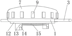
图1为本实用新型提出的一种便于安装的线条灯的正面剖视图;Fig. 1 is the front sectional view of a kind of line light that is easy to install proposed by the utility model;
图2为本实用新型提出的一种便于安装的线条灯的结构示意图;Fig. 2 is a structural schematic diagram of an easy-to-install line lamp proposed by the utility model;
图3为本实用新型提出的一种便于安装的线条灯的固定板俯视图。Fig. 3 is a top view of a fixing plate of a line light that is easy to install proposed by the utility model.
图例说明:illustration:
1、固定板;2、固定槽;3、导线;4、安装座;5、LED灯泡;6、固定环;7、灯罩;8、卡杆;9、防滑块;10、橡胶圈;11、支柱;12、安装板;13、安装柱;14、安装孔;15、夹板;16、滑孔。1. Fixing plate; 2. Fixing slot; 3. Wire; 4. Mounting seat; 5. LED bulb; 6. Fixing ring; 7. Lampshade; pillar; 12, mounting plate; 13, mounting column; 14, mounting hole; 15, splint; 16, sliding hole.
具体实施方式Detailed ways
下面将结合本实用新型实施例中的附图,对本实用新型实施例中的技术方案进行清楚、完整地描述,显然,所描述的实施例仅仅是本实用新型一部分实施例,而不是全部的实施例。基于本实用新型中的实施例,本领域普通技术人员在没有做出创造性劳动前提下所获得的所有其他实施例,都属于本实用新型保护的范围。The technical solutions in the embodiments of the present invention will be clearly and completely described below in conjunction with the accompanying drawings in the embodiments of the present invention. Obviously, the described embodiments are only part of the embodiments of the present invention, not all of them. example. Based on the embodiments of the present utility model, all other embodiments obtained by persons of ordinary skill in the art without making creative efforts belong to the scope of protection of the present utility model.
参照图1-3,本实用新型提供的一种实施例:一种便于安装的线条灯,包括固定板1,固定板1的顶面中部固定连接在安装座4的底面,安装座4的顶面固定连接有LED灯泡5,固定板1的顶面固定连接有固定环6,固定环6的外侧螺纹连接在灯罩7内壁的底部,灯罩7内壁顶面的中部两侧均固定连接有卡杆8,两个卡杆8相远离一面的底部设置在固定环6的内壁中部,灯罩7的外壁底部固定连接有防滑块9,工作时,通过固定板1底部设置的安装板12、安装孔14、夹板15、可对本线条灯进行固定,通过导线3可对内部的LED灯泡5供电,使其工作并进行照明,当内部的LED灯泡5出现故障需要进行维修时,通过旋转灯罩7,可将灯罩7从固定环6上取下,并且在旋转灯罩7使,防滑块9可增大手掌与灯罩7之间的摩擦力,使之更容易拧动灯罩7使其进行旋转,便于将灯罩7取下,当灯罩7被取下后,即可对安装座4上的LED灯泡5进行维修,当对LED灯泡5的维修结束后,将灯罩7重新拧紧在固定环6的外侧,并且在拧紧固定环6时,两个卡杆8相远离一面的底部可卡进固定环6内壁螺纹之间的缝隙中,从而可利用两个卡杆8将灯罩7紧紧固定在固定环6上,使灯罩7的装卸极为便利,便于后期对LED灯泡5的维修,并且在拧紧灯罩7时,可将橡胶圈10的底面压在固定板1的顶面,可提高灯罩7与固定板1之间密封性,避免蚊虫进入内部影响LED灯泡5的照明。Referring to Fig. 1-3, an embodiment provided by the utility model: an easy-to-install line light, including a
防滑块9有若干个,若干个防滑块9均匀分布在灯罩7外壁的底部,固定环6的内壁中部与外壁中部均设置有螺纹,固定环6外壁的螺纹与灯罩7内壁的底部螺纹连接,两个卡杆8相远离一侧的底部分别与固定环6内壁螺纹的两侧连接,固定板1的两侧均设置有固定槽2,两个固定槽2的内部均设置有导线3,且两个导线3均与LED灯泡5电性连接,灯罩7的底部固定连接有橡胶圈10,固定板1底面的中部固定连接在支柱11的顶部,支柱11的底部转动连接在夹板15的顶面中部,固定板1的底面和夹板15的顶面之间设置有安装板12,安装板12底面的中部两侧固定均转动连接有安装柱13,两个安装柱13的底部均设置有安装孔14,安装板12的中部设置有滑孔16,滑孔16的内壁设置在支柱11的外侧,并且通过两个安装柱13底部的安装孔14,可将本线条灯固定在细杆上,同时还可通过将平面上打孔,将安装柱13插进孔内,从而可将本线条灯安装在平面上,同时,通过夹板15可将本线条灯安装在板类的固定件上,通过安装柱13、安装孔14和夹板15之间的配合,可使本线条灯的适应性提高,并且两个安装柱13可单独旋转,改变安装孔14的角度,通过旋转安装板12可对两个安装柱13的位置进行调整,通过夹板15转动连接在支柱11的底部,还可对夹板15的角度进行调整,可进一步增加本线条灯适应性,使其便于后期的安装。There are several
工作原理:工作时,通过固定板1底部设置的安装板12、安装孔14、夹板15、可对本线条灯进行固定,通过导线3可对内部的LED灯泡5供电,使其工作并进行照明,当内部的LED灯泡5出现故障需要进行维修时,通过旋转灯罩7,可将灯罩7从固定环6上取下,并且在旋转灯罩7使,防滑块9可增大手掌与灯罩7之间的摩擦力,使之更容易拧动灯罩7使其进行旋转,便于将灯罩7取下,当灯罩7被取下后,即可对安装座4上的LED灯泡5进行维修,当对LED灯泡5的维修结束后,将灯罩7重新拧紧在固定环6的外侧,并且在拧紧固定环6时,两个卡杆8相远离一面的底部可卡进固定环6内壁螺纹之间的缝隙中,从而可利用两个卡杆8将灯罩7紧紧固定在固定环6上,使灯罩7的装卸极为便利,便于后期对LED灯泡5的维修,并且在拧紧灯罩7时,可将橡胶圈10的底面压在固定板1的顶面,可提高灯罩7与固定板1之间密封性,避免蚊虫进入内部影响LED灯泡5的照明。并且通过两个安装柱13底部的安装孔14,可将本线条灯固定在细杆上,同时还可通过将平面上打孔,将安装柱13插进孔内,从而可将本线条灯安装在平面上,同时,通过夹板15可将本线条灯安装在板类的固定件上,通过安装柱13、安装孔14和夹板15之间的配合,可使本线条灯的适应性提高,并且两个安装柱13可单独旋转,改变安装孔14的角度,通过旋转安装板12可对两个安装柱13的位置进行调整,通过夹板15转动连接在支柱11的底部,还可对夹板15的角度进行调整,可进一步增加本线条灯适应性,使其便于后期的安装。Working principle: when working, the line light can be fixed through the
最后应说明的是:以上所述仅为本实用新型的优选实施例而已,并不用于限制本实用新型,尽管参照前述实施例对本实用新型进行了详细的说明,对于本领域的技术人员来说,其依然可以对前述各实施例所记载的技术方案进行修改,或者对其中部分技术特征进行等同替换,凡在本实用新型的精神和原则之内,所作的任何修改、等同替换、改进等,均应包含在本实用新型的保护范围之内。Finally, it should be noted that: the above is only a preferred embodiment of the utility model, and is not intended to limit the utility model, although the utility model has been described in detail with reference to the foregoing embodiments, for those skilled in the art , it can still modify the technical solutions recorded in the foregoing embodiments, or perform equivalent replacements on some of the technical features. Any modifications, equivalent replacements, improvements, etc. made within the spirit and principles of the present utility model, All should be included within the protection scope of the present utility model.
Claims (8)
Priority Applications (1)
| Application Number | Priority Date | Filing Date | Title |
|---|---|---|---|
| CN202222319761.6U CN218379274U (en) | 2022-09-01 | 2022-09-01 | Line lamp convenient to installation |
Applications Claiming Priority (1)
| Application Number | Priority Date | Filing Date | Title |
|---|---|---|---|
| CN202222319761.6U CN218379274U (en) | 2022-09-01 | 2022-09-01 | Line lamp convenient to installation |
Publications (1)
| Publication Number | Publication Date |
|---|---|
| CN218379274U true CN218379274U (en) | 2023-01-24 |
Family
ID=84972337
Family Applications (1)
| Application Number | Title | Priority Date | Filing Date |
|---|---|---|---|
| CN202222319761.6U Expired - Fee Related CN218379274U (en) | 2022-09-01 | 2022-09-01 | Line lamp convenient to installation |
Country Status (1)
| Country | Link |
|---|---|
| CN (1) | CN218379274U (en) |
-
2022
- 2022-09-01 CN CN202222319761.6U patent/CN218379274U/en not_active Expired - Fee Related
Similar Documents
| Publication | Publication Date | Title |
|---|---|---|
| CN219775509U (en) | Novel spot lamp capable of being buried in ceiling | |
| CN207880599U (en) | A kind of LED tunnel lamp of adjustable mounting base | |
| CN207213735U (en) | A kind of desk lamp for being conveniently replaceable bulb | |
| CN211952346U (en) | High-stability LED line lamp mounting device | |
| CN205299333U (en) | A two-way rotating LED downlight | |
| CN211010924U (en) | L ED lamp with high heat dissipation performance | |
| CN206268930U (en) | LED projector lamp | |
| CN206207230U (en) | An embedded LED ceiling lamp | |
| CN221958821U (en) | T-shaped lamp | |
| CN219588851U (en) | Atmosphere lighthouse | |
| CN205480573U (en) | LED smallpox shot -light convenient to adjust | |
| CN217875429U (en) | Stage lighting equipment sight LED lamps and lanterns | |
| CN213019144U (en) | Festival decorative lamp mount pad convenient to dismouting | |
| CN207094232U (en) | A kind of LED bulb lamp | |
| CN222783401U (en) | A lamp fixing frame for indoor and outdoor lighting engineering | |
| CN205299380U (en) | A multifunctional chandelier | |
| CN218845980U (en) | Fixing structure of LED lighting device | |
| CN223869085U (en) | A quick-release downlight | |
| CN205640648U (en) | A flat street light | |
| CN207112551U (en) | A kind of LED turns to underground lamp | |
| CN205227101U (en) | Lantern shot -light | |
| CN223512017U (en) | A spotlight holder structure | |
| CN203162789U (en) | European LED lamp | |
| CN210004272U (en) | A new type of road lighting | |
| CN216243872U (en) | A LED downlight board |
Legal Events
| Date | Code | Title | Description |
|---|---|---|---|
| GR01 | Patent grant | ||
| GR01 | Patent grant | ||
| CF01 | Termination of patent right due to non-payment of annual fee |
Granted publication date: 20230124 |