CN218378321U - Process pipeline guide shower valve plugging device - Google Patents
Process pipeline guide shower valve plugging device Download PDFInfo
- Publication number
- CN218378321U CN218378321U CN202121832415.7U CN202121832415U CN218378321U CN 218378321 U CN218378321 U CN 218378321U CN 202121832415 U CN202121832415 U CN 202121832415U CN 218378321 U CN218378321 U CN 218378321U
- Authority
- CN
- China
- Prior art keywords
- cover
- plugging
- stopping
- arc
- leak
- Prior art date
- Legal status (The legal status is an assumption and is not a legal conclusion. Google has not performed a legal analysis and makes no representation as to the accuracy of the status listed.)
- Active
Links
Images


Landscapes
- Pipe Accessories (AREA)
Abstract
本实用新型涉及一种工艺管线导淋阀门堵漏装置。其技术方案是:在输入管的上侧安装上弧形堵漏罩,在输入管的下侧安装下弧形堵漏罩,左端通过固定螺栓和四氟胶带连接,右端连接堵漏端盖,通过上弧形堵漏罩、下弧形堵漏罩和堵漏端盖将导淋阀门包裹固定,所述堵漏端盖右侧的输出管安装排污球阀。有益效果是:本实用新型通过使上弧形堵漏罩和下弧形堵漏罩组合形成筒形结构,再与堵漏端盖插接配合,使上弧形堵漏罩、下弧形堵漏罩和堵漏端盖组合成封闭桶状结构;在堵漏端盖后侧的输出管上增加排污球阀,方便带压安装,避免了停用此管线造成装置停工减产,及避免了停工过程中带来的风险。

The utility model relates to a leak-stopping device for a process pipeline drench valve. The technical solution is: install an upper arc-shaped leak-stopping cover on the upper side of the input pipe, install a lower arc-shaped leak-stopping cover on the lower side of the input pipe, connect the left end with a fixing bolt and PTFE tape, and connect the plugging end cover at the right end. The drain valve is wrapped and fixed by the upper arc plugging cover, the lower arc plugging cover and the plugging end cap, and the output pipe on the right side of the plugging end cap is equipped with a sewage ball valve. The beneficial effects are: the utility model forms a cylindrical structure by combining the upper arc plugging cover and the lower arc plugging cover, and then plugs and cooperates with the plugging end cover, so that the upper arc plugging cover and the lower arc plugging The leakage cover and the plugging end cover are combined to form a closed barrel structure; a sewage ball valve is added to the output pipe on the back side of the plugging end cover to facilitate installation under pressure, avoiding the shutdown of the device and production reduction caused by the shutdown of the pipeline, and avoiding the shutdown process risks posed by.
Description
技术领域technical field
本实用新型涉及一种工艺管线堵漏装置,特别涉及一种工艺管线导淋阀门堵漏装置。The utility model relates to a leak-stopping device for a process pipeline, in particular to a leak-stopping device for a leak-guiding valve of a process pipeline.
背景技术Background technique
目前,在化工装置工艺管线一般都设有导淋阀门,导淋阀门的法兰或者阀门体的局部一旦泄露,只能采取停止此工艺管线物料输送,进行阀门或垫片更换措施,如果此工艺管线是生产过程中极为重要的管线,那么装置只能停工,因此会造成生产减产以及带来开停工过程中安全隐患。At present, the process pipelines of chemical plants are generally equipped with deluge valves. Once the flange of the deluge valve or part of the valve body leaks, the only way to stop the material delivery of the process pipeline is to replace the valve or gasket. If the process The pipeline is an extremely important pipeline in the production process, so the device can only be shut down, which will cause production reduction and bring safety hazards during the start-up and shutdown process.
实用新型内容Utility model content
本实用新型的目的就是针对现有技术存在的上述缺陷,提供一种工艺管线导淋阀门堵漏装置,通过构件组合连接的方式将泄漏点密封,避免停用此管线造成装置停工减产,及避免停工过程中带来的风险。The purpose of this utility model is to aim at the above-mentioned defects existing in the prior art, and to provide a leak-stopping device for a process pipeline drain valve, which seals the leak point through the combined connection of components, avoiding the shutdown of the pipeline caused by the shutdown of the pipeline, and avoiding Risks during shutdown.
本实用新型提到的一种工艺管线导淋阀门堵漏装置,其技术方案是:包括输入管(1)、导淋阀门(2)和输出管(3),所述在输入管(1)和输出管(3)之间设有导淋阀门(2),其改进之处是:还包括上弧形堵漏罩(4)、下弧形堵漏罩(5)、固定螺栓(6)、四氟胶带(7)、紧固卡扣(8)、堵漏端盖(9)和排污球阀(10),在输入管(1)的上侧安装上弧形堵漏罩(4),在输入管(1)的下侧安装下弧形堵漏罩(5),所述的上弧形堵漏罩(4)和下弧形堵漏罩(5)的左端通过固定螺栓(6)和四氟胶带(7)连接,所述的上弧形堵漏罩(4)和下弧形堵漏罩(5)的右端连接堵漏端盖(9),通过上弧形堵漏罩(4)、下弧形堵漏罩(5)和堵漏端盖(9)将导淋阀门(2)包裹固定,所述堵漏端盖(9)右侧的输出管(3)安装排污球阀(10)。A leak-stopping device for a process pipeline drench valve mentioned in the utility model, its technical proposal is: comprising an input pipe (1), a drench valve (2) and an output pipe (3), the input pipe (1) There is a deluge valve (2) between it and the output pipe (3), and its improvement is that it also includes an upper arc-shaped leak-stopping cover (4), a lower arc-shaped leak-stopping cover (5), and fixing bolts (6) , PTFE tape (7), fastening buckle (8), plugging end cap (9) and sewage ball valve (10), install an arc plugging cover (4) on the upper side of the input pipe (1), Install the lower arc-shaped leak-stopping cover (5) on the lower side of the input pipe (1), and the left ends of the upper arc-shaped leak-stopping cover (4) and the lower arc-shaped leak-stopping cover (5) pass through the fixing bolts (6) Connect with PTFE tape (7), the right ends of the upper arc-shaped leak-stopping cover (4) and the lower arc-shaped leak-stopping cover (5) are connected to the plugging end cap (9), through the upper arc-shaped leak-stopping cover ( 4), the lower arc plugging cover (5) and the plugging end cap (9) wrap and fix the drain valve (2), and the output pipe (3) on the right side of the plugging end cap (9) is installed with a sewage ball valve (10).
优选的,上述的上弧形堵漏罩(4)由外罩体(4.1)和连接体(4.2)组成,所述外罩体(4.1)为半圆筒形结构,连接体(4.2)上设有连接螺孔(4.3)。Preferably, the above-mentioned upper arc plugging cover (4) is composed of an outer cover (4.1) and a connecting body (4.2), the outer covering (4.1) is a semi-cylindrical structure, and the connecting body (4.2) is provided with a connecting Screw holes (4.3).
优选的,上述的连接体(4.2)为半圆筒形结构,且连接体(4.2)的内径大于输入管(1)的外径。Preferably, the above-mentioned connecting body (4.2) has a semi-cylindrical structure, and the inner diameter of the connecting body (4.2) is larger than the outer diameter of the input pipe (1).
优选的,上述的外罩体(4.1)的内径长度大于导淋阀门(2)的高度。Preferably, the length of the inner diameter of the outer cover body (4.1) is greater than the height of the shower valve (2).
优选的,上述的堵漏端盖(9)包括端盖主体(9.1)和插接母凸起(9.2),所述端盖主体(9.1)为圆形结构,在端盖主体(9.1)的内侧设有环形的插接母凸起(9.2),通过插接母凸起(9.2)与上弧形堵漏罩(4)和下弧形堵漏罩(5)插接。Preferably, the above-mentioned plugging end cap (9) includes an end cap body (9.1) and a plug-in female protrusion (9.2), the end cap body (9.1) is a circular structure, and The inner side is provided with a ring-shaped plug-in female protrusion (9.2), through which the plug-in female protrusion (9.2) is plugged with the upper arc-shaped leak plugging cover (4) and the lower arc-shaped leak plugging cover (5).
优选的,上述的插接母凸起(9.2)上设有紧固卡扣(8),通过紧固卡扣(8)将插接后的堵漏端盖(9)与上弧形堵漏罩(4)和下弧形堵漏罩(5)固定连接。Preferably, the above-mentioned plug-in female protrusion (9.2) is provided with a fastening buckle (8), through the fastening buckle (8), the plugged plugging end cap (9) and the upper arc plugging The cover (4) is fixedly connected with the lower arc plugging cover (5).
本实用新型的有益效果是:本实用新型通过使上弧形堵漏罩和下弧形堵漏罩组合形成筒形结构,再与堵漏端盖插接配合,使上弧形堵漏罩、下弧形堵漏罩和堵漏端盖组合成封闭桶状结构;在堵漏端盖后侧的输出管上增加排污球阀,方便带压安装,安装时打开,使管线内物料排出,防止压力过高,可以定期打开排污,避免了停用此管线造成装置停工减产,及避免了停工过程中带来的风险。The beneficial effects of the utility model are: the utility model forms a cylindrical structure by combining the upper arc plugging cover and the lower arc plugging cover, and then plugs and cooperates with the plugging end cover, so that the upper arc plugging cover, The lower arc plugging cover and the plugging end cover are combined into a closed barrel structure; a sewage ball valve is added to the output pipe on the back side of the plugging end cover to facilitate installation under pressure. If it is too high, the sewage can be opened regularly, which avoids the shutdown and production reduction of the device caused by the shutdown of this pipeline, and avoids the risks brought about by the shutdown process.
附图说明Description of drawings
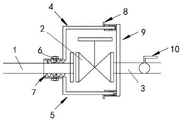
图1是本实用新型的安装在导淋阀门上的整体结构示意图;Fig. 1 is a schematic diagram of the overall structure of the utility model installed on the shower valve;
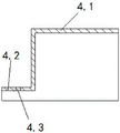
图2是上弧形堵漏罩的结构示意图;Fig. 2 is a schematic structural view of an upper arc-shaped leak-stopping cover;
图3是上弧形堵漏罩和下弧形堵漏罩组装后的侧视图;Fig. 3 is a side view after the upper arc-shaped leak-stopping cover and the lower arc-shaped leak-stopping cover are assembled;
图4是堵漏端盖的结构示意图;Fig. 4 is the structural representation of plugging end cap;
上图中:输入管1、导淋阀门2、输出管3、上弧形堵漏罩4、下弧形堵漏罩5、固定螺栓6、四氟胶带7、紧固卡扣8、堵漏端盖9、排污球阀10、密封垫11,外罩体4.1、连接体4.2、连接螺孔4.3,端盖主体9.1和插接母凸起9.2。In the above picture:
具体实施方式Detailed ways
以下结合附图对本实用新型的优选实施例进行说明,应当理解,此处所描述的优选实施例仅用于说明和解释本实用新型,并不用于限定本实用新型。The preferred embodiments of the present utility model are described below in conjunction with the accompanying drawings. It should be understood that the preferred embodiments described here are only used to illustrate and explain the present utility model, and are not intended to limit the present utility model.
实施例1,参照图1和图3,本实用新型提到的一种工艺管线导淋阀门堵漏装置,包括输入管1、导淋阀门2和输出管3,所述在输入管1和输出管3之间设有导淋阀门2,其改进之处是:还包括上弧形堵漏罩4、下弧形堵漏罩5、固定螺栓6、四氟胶带7、紧固卡扣8、堵漏端盖9和排污球阀10,在输入管1的上侧安装上弧形堵漏罩4,在输入管1的下侧安装下弧形堵漏罩5,所述的上弧形堵漏罩4和下弧形堵漏罩5的左端通过固定螺栓6和四氟胶带7连接,所述的上弧形堵漏罩4和下弧形堵漏罩5的右端连接堵漏端盖9,通过上弧形堵漏罩4、下弧形堵漏罩5和堵漏端盖9将导淋阀门2包裹固定,所述堵漏端盖9右侧的输出管3安装排污球阀10。
参照图2,上述的上弧形堵漏罩4由外罩体4.1和连接体4.2组成,所述外罩体4.1为半圆筒形结构,连接体4.2上设有连接螺孔4.3。Referring to Fig. 2, the above-mentioned upper arc-shaped
其中,上述的连接体4.2为半圆筒形结构,且连接体4.2的内径大于输入管1的外径,便于安装在输入管外侧;上述的外罩体4.1的内径长度大于导淋阀门2的高度,便于外罩体4.1将导淋阀门整体套住。Wherein, the above-mentioned connecting body 4.2 is a semi-cylindrical structure, and the inner diameter of the connecting body 4.2 is larger than the outer diameter of the
参照图4,上述的堵漏端盖9包括端盖主体9.1和插接母凸起9.2,所述端盖主体9.1为圆形结构,在端盖主体9.1的内侧设有环形的插接母凸起9.2,通过插接母凸起9.2与上弧形堵漏罩4和下弧形堵漏罩5插接。Referring to Fig. 4, the above-mentioned
其中,上述的插接母凸起9.2上设有紧固卡扣8,通过紧固卡扣8将插接后的堵漏端盖9与上弧形堵漏罩4和下弧形堵漏罩5固定连接。Among them, the above-mentioned plug-in female protrusion 9.2 is provided with a fastening
本实用新型使用时,在导淋阀门2的漏点外侧,在漏点的输入管1上缠绕四氟胶带7,然后,使上弧形堵漏罩4和下弧形堵漏罩5组合形成筒形结构,左端通过固定螺栓6固定在输入管上;所述的上弧形堵漏罩4和下弧形堵漏罩5的右端与堵漏端盖9配合插接,再通过紧固卡扣8固定;使上弧形堵漏罩4、下弧形堵漏罩5和堵漏端盖9组合成封闭桶状结构;When the utility model is in use, on the outside of the leakage point of the
在堵漏端盖9后侧的输出管3上增加排污球阀10,方便带压安装,安装时打开,使管线内物料排出,防止压力过高,安装完成后,关闭排污球阀10,之后定期打开排污,避免了停用此管线造成装置停工减产,及避免了停工过程中带来的风险。Add a sewage
实施例2,参照图1和图3,本实用新型提到的一种工艺管线导淋阀门堵漏装置,包括输入管1、导淋阀门2和输出管3,所述在输入管1和输出管3之间设有导淋阀门2,其改进之处是:还包括上弧形堵漏罩4、下弧形堵漏罩5、固定螺栓6、四氟胶带7、紧固卡扣8、堵漏端盖9和排污球阀10,在输入管1的上侧安装上弧形堵漏罩4,在输入管1的下侧安装下弧形堵漏罩5,所述的上弧形堵漏罩4和下弧形堵漏罩5的左端通过固定螺栓6和四氟胶带7连接,所述的上弧形堵漏罩4和下弧形堵漏罩5的右端连接堵漏端盖9,通过上弧形堵漏罩4、下弧形堵漏罩5和堵漏端盖9将导淋阀门2包裹固定,所述堵漏端盖9右侧的输出管3安装排污球阀10。
与实施例1不同之处是:上弧形堵漏罩4和下弧形堵漏罩5之间的接触部位设有密封垫11,再结合左端部的四氟胶带7,堵漏端盖9与输出管3之间也设有密封垫,从而使上弧形堵漏罩4、下弧形堵漏罩5和堵漏端盖9形成更好的密闭空腔。The difference from Example 1 is that a sealing
以上所述,仅是本实用新型的较佳实施例,任何熟悉本领域的技术人员均可能利用上述阐述的技术方案对本实用新型加以修改或将其修改为等同的技术方案。因此,依据本实用新型的技术方案所进行的任何简单修改或等同变换,尽属于本实用新型要求保护的范围。The above are only preferred embodiments of the present utility model, and any person skilled in the art may use the above-mentioned technical solutions to modify the present utility model or modify it into an equivalent technical solution. Therefore, any simple modification or equivalent transformation carried out according to the technical solution of the utility model belongs to the protection scope of the utility model.
Claims (6)
Priority Applications (1)
| Application Number | Priority Date | Filing Date | Title |
|---|---|---|---|
| CN202121832415.7U CN218378321U (en) | 2021-08-06 | 2021-08-06 | Process pipeline guide shower valve plugging device |
Applications Claiming Priority (1)
| Application Number | Priority Date | Filing Date | Title |
|---|---|---|---|
| CN202121832415.7U CN218378321U (en) | 2021-08-06 | 2021-08-06 | Process pipeline guide shower valve plugging device |
Publications (1)
| Publication Number | Publication Date |
|---|---|
| CN218378321U true CN218378321U (en) | 2023-01-24 |
Family
ID=84950567
Family Applications (1)
| Application Number | Title | Priority Date | Filing Date |
|---|---|---|---|
| CN202121832415.7U Active CN218378321U (en) | 2021-08-06 | 2021-08-06 | Process pipeline guide shower valve plugging device |
Country Status (1)
| Country | Link |
|---|---|
| CN (1) | CN218378321U (en) |
-
2021
- 2021-08-06 CN CN202121832415.7U patent/CN218378321U/en active Active
Similar Documents
| Publication | Publication Date | Title |
|---|---|---|
| CN211525767U (en) | An easy-to-use mechanical seal | |
| CN208060096U (en) | A kind of assembled air conditioner water device for testing steel pipe pressure | |
| CN207005285U (en) | A kind of rubber seal with inner liner metal skeleton | |
| CN109268600B (en) | Quick clamping's pipeline connection structure | |
| CN110043724A (en) | A kind of flaring hoop type pipeline connector | |
| CN201650184U (en) | A hole sealer that can seal the cracks around the hole | |
| CN214008488U (en) | Natural gas line takes gas plugging device | |
| CN218494475U (en) | A protective structure for a natural gas outer casing | |
| CN207279082U (en) | A kind of PVC drain pipe pipe connecting | |
| CN205534813U (en) | Pipeline plugging device | |
| CN206738650U (en) | A kind of natural gas valve | |
| CN219755652U (en) | Leakage-proof connecting structure based on natural gas pipeline | |
| CN220688404U (en) | Socket joint for plastic drain pipe rush repair | |
| CN106499886B (en) | A kind of multi-sealed cutting ferrule of combination | |
| CN220957298U (en) | Stainless steel spiral corrugated pipe internal thread connecting piece | |
| CN221762988U (en) | A high-sealing internal and external thread plug | |
| CN223690505U (en) | An antistatic valve | |
| CN220134913U (en) | Corrugated hose joint | |
| CN206608641U (en) | A kind of pipe connecting structure | |
| CN210890539U (en) | A kind of oil pipe quick connect joint | |
| CN219606396U (en) | Gas pipeline rush repair plugging assembly | |
| CN221922514U (en) | Pipeline plugging device | |
| CN219549850U (en) | Leak protection liquid flange subassembly | |
| CN218510432U (en) | Gas pipeline gas leakage hole plugging device | |
| CN216952076U (en) | Threaded movable joint for threaded pipe fitting |
Legal Events
| Date | Code | Title | Description |
|---|---|---|---|
| GR01 | Patent grant | ||
| GR01 | Patent grant | ||
| CP03 | Change of name, title or address | ||
| CP03 | Change of name, title or address |
Address after: 198 Tongxing Road, Kenli District, Dongying City, Shandong Province Patentee after: Shenghua new energy technology (Dongying) Co.,Ltd. Country or region after: China Patentee after: Shi Dashenghua New Materials Group Co.,Ltd. Address before: 198 Tongxing Road, Kenli District, Dongying City, Shandong Province Patentee before: Shenghua new energy technology (Dongying) Co.,Ltd. Country or region before: China Patentee before: Shenghua New Material Group Co.,Ltd. |