CN218374129U - Silt clean-up equipment for hydraulic engineering - Google Patents
Silt clean-up equipment for hydraulic engineering Download PDFInfo
- Publication number
- CN218374129U CN218374129U CN202222400331.7U CN202222400331U CN218374129U CN 218374129 U CN218374129 U CN 218374129U CN 202222400331 U CN202222400331 U CN 202222400331U CN 218374129 U CN218374129 U CN 218374129U
- Authority
- CN
- China
- Prior art keywords
- silt
- sludge
- cleaning
- mounting plate
- shaft
- Prior art date
- Legal status (The legal status is an assumption and is not a legal conclusion. Google has not performed a legal analysis and makes no representation as to the accuracy of the status listed.)
- Active
Links
Images


Landscapes
- Treatment Of Sludge (AREA)
Abstract
The utility model discloses a silt cleaning equipment for hydraulic engineering, including the silt cleaning truck with install the mud holding vessel in silt cleaning truck upper end, install the jib hoist on the silt cleaning truck, jib hoist bottom connection has silt cleaning mechanism, silt cleaning mechanism is including clearing up the mounting panel, the soil pick-up pump, ripple takes out the mud hose, stereoplasm mud pipe, n type mounting panel, asynchronous motor is stretched to the biax, the (mixing) shaft, a plurality of stirring vane, the transmission shaft, initiative chain tooth, the axis of rotation, driven chain tooth, drive chain and a set of relative helical blade. The beneficial effects of the utility model are that, silt clearance mechanism adopts a set of relative helical blade can push away silt to stereoplasm and takes out mud pipe department, debris such as stones in the stainless steel filter screen filterable silt, and a plurality of stirring vane can stir silt, prevents that the pipeline from taking place blocking phenomenon, and a set of toper flotation pontoon can prevent that the clearance mounting panel from being absorbed in the silt in, simultaneously, is convenient for remove silt clearance mechanism.
Description
Technical Field
The utility model relates to a hydraulic engineering field specifically is a silt clean-up equipment for hydraulic engineering.
Background
Hydraulic engineering is a general term for various engineering constructions built for controlling, utilizing and protecting water resources and environments on the earth surface and underground. The service objects are divided into flood control engineering, farmland hydraulic engineering, hydroelectric power engineering, channel and harbor engineering, water supply and drainage engineering, environmental hydraulic engineering, coastal reclamation engineering and the like.
The method is characterized in that sludge in the river channel needs to be cleaned in the river channel treatment process, generally, after water in the river channel is completely pumped out, the sludge on the surface layer is completely absorbed into a tank car by a sewage suction pump and then is conveyed to a soil unloading point. Application number CN202021072043.8 in the existing patent discloses a silt cleaning device for water environment treatment, which filters and extracts river silt through a silt collecting barrel. However, the sludge is sucked by the sludge collecting barrel, the sludge suction range is small, the sludge in the river channel is long in settling time and difficult to clean, and sundries such as stones in the sludge easily damage the sludge suction pump.
SUMMERY OF THE UTILITY MODEL
To above defect, the utility model provides a silt clean-up equipment for hydraulic engineering to solve river course silt clearance problem.
In order to achieve the above purpose, the utility model adopts the following technical scheme:
a silt cleaning device for hydraulic engineering comprises a silt cleaning vehicle and a silt storage tank arranged at the upper rear end of the silt cleaning vehicle, wherein a boom crane is arranged on the silt cleaning vehicle, and a silt cleaning mechanism is connected to the bottom of the boom crane;
silt clearance mechanism stretches asynchronous motor, (mixing) shaft, a plurality of stirring vane, transmission shaft, initiative chain tooth, axis of rotation, driven chain tooth, drive chain and a set of relative helical blade including clearance mounting panel, soil pick-up pump, ripple, stereoplasm mud pumping pipe, n type mounting panel, biax, the clearance mounting panel is the rectangle, the soil pick-up pump is installed and is being cleared up mounting panel upper end center department, ripple soil pick-up hose cartridge is in soil pick-up pump bottom suction mouth, stereoplasm mud pumping pipe upper end and ripple soil pick-up hose intercommunication, n type mounting panel is installed in stereoplasm mud pumping pipe bottom, the biax is stretched asynchronous motor horizontal installation and is right side on n type mounting panel, the activity cartridge of (mixing) shaft is in stereoplasm mud pumping pipe, and the right-hand member stretches asynchronous motor left side rotation end with the biax and is connected, and a plurality of stirring vane evenly installs on the (mixing) shaft, the transmission shaft is installed and is stretched asynchronous motor right side rotation end, initiative chain tooth is installed at the transmission shaft right-hand member, the axis of rotation activity is in n type mounting panel, and the right-hand member stretches out n type mounting panel, and driven chain tooth is installed on the external surface at the initiative chain tooth, a set of spiral chain tooth.
Furthermore, the sludge storage tank is connected with a sewage outlet of the sewage suction pump through a sludge outlet hose and is of a detachable structure.
Furthermore, a connecting frame is installed on the cleaning installation plate, and the suspender crane is connected with the connecting frame through a lifting rope.
Furthermore, the bottom of the hard mud pumping pipe is inserted into the center of the upper end of the n-shaped mounting plate, and a stainless steel filter screen is arranged at the bottom of the hard mud pumping pipe.
Furthermore, a group of conical buoys are installed on two sides of the cleaning installation plate through two groups of hoops.
Furthermore, a group of sliding rods is movably inserted into two sides of the cleaning installation plate, the bottoms of the group of sliding rods are respectively connected with the n-shaped installation plate, and the outer surface of the upper end of the group of sliding rods is sleeved with a buffer spring.
The utility model provides a silt cleaning equipment for hydraulic engineering, possess following beneficial effect, it can push away silt to stereoplasm mud pipe department to adopt a set of relative helical blade to adopt through being located jib hoist crane bottom to be connected with silt cleaning mechanism, debris such as stone in the stainless steel filter screen filterable silt, a plurality of stirring vane can stir silt, prevent that the pipeline from taking place blocking phenomenon, a set of toper flotation pontoon can prevent that the clearance mounting panel from being absorbed in the silt, and simultaneously, be convenient for remove silt cleaning mechanism.
Drawings
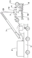
Fig. 1 is the utility model relates to a silt clean-up equipment schematic diagram for hydraulic engineering.
Fig. 2 is the schematic view of the sludge cleaning mechanism of the utility model.
Fig. 3 is a schematic view of the installation of the conical float bowl of the present invention.
Fig. 4 is a schematic view of the n-type mounting plate of the present invention.
In the figure: 1. a sludge cleaning vehicle; 2. a sludge storage tank; 3. a boom crane; 4. cleaning the mounting plate; 5. a sewage suction pump; 6. a corrugated mud pumping hose; 7. a hard mud pumping pipe; 8. an n-type mounting plate; 9. a double-shaft extension asynchronous motor; 10. a stirring shaft; 11. a stirring blade; 12. a drive shaft; 13. a drive chain tooth; 14. a rotating shaft; 15. a driven chain tooth; 16. a drive chain; 17. a helical blade; 18. a mud discharging hose; 19. a connecting frame; 20. a lifting rope; 21. a stainless steel filter screen; 22. hooping; 23. a conical buoy; 24. a slide bar; 25. a buffer spring.
Detailed Description
The invention is described in detail below with reference to the accompanying drawings, as shown in fig. 1-4: a silt cleaning device for hydraulic engineering comprises a silt cleaning vehicle 1 and a silt storage tank 2 arranged at the upper rear end of the silt cleaning vehicle 1, wherein a boom crane 3 is arranged on the silt cleaning vehicle 1, and a silt cleaning mechanism is connected to the bottom of the boom crane 3; the sludge cleaning mechanism comprises a cleaning mounting plate 4, a sewage suction pump 5, a corrugated sludge pumping hose 6, a hard sludge pumping pipe 7, an n-type mounting plate 8, a double-shaft extension asynchronous motor 9, a stirring shaft 10, a plurality of stirring blades 11, a transmission shaft 12, driving chain teeth 13, a rotating shaft 14, driven chain teeth 15, a transmission chain 16 and a group of opposite spiral blades 17, wherein the cleaning mounting plate 4 is rectangular, the sewage suction pump 5 is arranged at the upper end center of the cleaning mounting plate 4, the corrugated sludge pumping hose 6 is inserted into a sludge pumping hole at the bottom of the sewage suction pump 5, the upper end of the hard sludge pumping pipe 7 is communicated with the corrugated sludge pumping hose 6, the n-type mounting plate 8 is arranged at the bottom of the hard sludge pumping pipe 7, the double-shaft extension asynchronous motor 9 is horizontally arranged on the right side of the n-shaped mounting plate 8, the stirring shaft 10 is movably inserted in the hard mud pumping pipe 7, the right end of the stirring shaft is connected with the left rotating end of the double-shaft extension asynchronous motor 9, a plurality of stirring blades 11 are uniformly arranged on the stirring shaft 10, the transmission shaft 12 is arranged on the right rotating end of the double-shaft extension asynchronous motor 9, the driving chain teeth 13 are arranged on the right end of the transmission shaft 12, the rotating shaft 14 is movably inserted in the n-shaped mounting plate 8, the right end of the rotating shaft extends out of the n-shaped mounting plate 8, the driven chain teeth 15 are arranged on the right end of the rotating shaft 14, the transmission chain 16 is sleeved on the driving chain teeth 13 and the driven chain teeth 15, and a group of opposite spiral blades 17 are arranged on two sides of the outer surface of the rotating shaft 14; the sludge storage tank 2 is connected with a sewage outlet of the sewage suction pump 5 through a sludge outlet hose 18 and is of a detachable structure; the cleaning installation plate 4 is provided with a connecting frame 19, and the boom crane 3 is connected with the connecting frame 19 through a lifting rope 20; the bottom of the hard mud pumping pipe 7 is inserted in the center of the upper end of the n-shaped mounting plate 8, and a stainless steel filter screen 21 is arranged at the bottom of the hard mud pumping pipe 7; a group of conical buoys 23 are arranged on two sides of the cleaning installation plate 4 through two groups of anchor ears 22; a group of sliding rods 24 is movably inserted on two sides of the cleaning mounting plate 4, the bottoms of the group of sliding rods 24 are respectively connected with the n-shaped mounting plate 8, and the outer surface of the upper end of the group of sliding rods 24 is sleeved with a buffer spring 25.
The working principle of the embodiment is as follows: when the device is used, a user firstly starts the suspender crane 3, moves the sludge cleaning mechanism into a river channel through the lifting rope 20, enables the n-shaped mounting plate 8 to be positioned in the sludge of the river channel, and then connects the sewage suction pump 5 with the sludge storage tank 2 through the sludge outlet hose 18;
when sludge is cleaned: the sewage suction pump 5 firstly starts to work, the sewage suction pump 5 is arranged at the center of the upper end of a cleaning installation plate 4, a corrugated sludge pumping hose 6 is inserted into a sludge pumping port at the bottom of the sewage suction pump 5, the upper end of a hard sludge pumping pipe 7 is communicated with the corrugated sludge pumping hose 6, the sewage suction pump 5 can pump sludge in a river channel through the hard sludge pumping pipe 7, then a double-shaft-stretching asynchronous motor 9 starts to work, the double-shaft-stretching asynchronous motor 9 is horizontally arranged on the right side of an n-shaped installation plate 8, a stirring shaft 10 is movably inserted into the hard sludge pumping pipe 7 through a fastening bearing, the right end is connected with the left rotating end of the double-shaft-stretching asynchronous motor 9, a plurality of stirring blades 11 are uniformly arranged on the stirring shaft 10, a transmission shaft 12 is arranged on the right rotating end of the double-shaft-stretching asynchronous motor 9, a driving chain tooth 13 is arranged on the right end of the transmission shaft 12, a rotating shaft 14 is movably inserted into the n-shaped installation plate 8 through the fastening bearing, and the right end extends out of the n-shaped installation plate 8, the driven chain teeth 15 are installed at the right end of the rotating shaft 14, the transmission chain 16 is sleeved on the driving chain teeth 13 and the driven chain teeth 15, a group of opposite helical blades 17 are installed at two sides of the outer surface of the rotating shaft 14, as shown in fig. 2, the double-shaft extension asynchronous motor 9 firstly drives the group of opposite helical blades 17 on the rotating shaft 14 to rotate through the transmission chain 16, the group of opposite helical blades 17 can push river sludge to the bottom of the hard sludge pumping pipe 7, so that the hard sludge pumping pipe 7 can pump the sludge, the bottom of the hard sludge pumping pipe 7 is inserted in the center of the upper end of the n-shaped mounting plate 8, the bottom of the hard sludge pumping pipe 7 is provided with a stainless steel filter screen 21, the stainless steel filter screen 21 can filter impurities such as stones in the sludge, and the like, meanwhile, the double-shaft extension asynchronous motor 9 drives a plurality of stirring blades 11 through the stirring shaft 10 to stir the sludge pumped into the hard sludge pumping pipe 7, the phenomenon of pipeline blockage is prevented, and sludge finally enters the sludge storage tank 2 through the sludge outlet hose 18;
the protecting shells are respectively installed outside the double-shaft-extension asynchronous motor 9 and the transmission chain 16, the protecting effect can be achieved, a group of conical floating cylinders 23 are installed on two sides of the cleaning installation plate 4 through two groups of hoops 22, the group of conical floating cylinders 23 can prevent the cleaning installation plate 4 from being sunk into sludge, meanwhile, the sludge cleaning mechanism can be conveniently moved, a group of sliding rods 24 are movably inserted on two sides of the cleaning installation plate 4, the bottoms of the group of sliding rods 24 are respectively connected with the n-type installation plate 8, the buffer springs 25 are sleeved on the outer surface of the upper ends of the group of sliding rods 24, when the n-type installation plate 8 descends into sludge in a river channel, the buffer springs 25 can play a buffering role, the sludge cleaning mechanism is connected to the bottom of the boom crane 3 through the position, the group of relative spiral blades 17 can push the sludge to the hard sludge pumping pipe 7, the stainless steel filter screen 21 can filter sundries such as stones in the sludge, the plurality of stirring blades 11 can stir the sludge, the pipeline blockage phenomenon can be prevented, the group of conical floating cylinders 23 can prevent the cleaning installation plate 4 from being sunk into the sludge, and meanwhile, the cleaning mechanism can be conveniently moved.
Above-mentioned technical scheme has only embodied the utility model discloses technical scheme's preferred technical scheme, some changes that this technical field's technical staff probably made to some parts wherein have all embodied the utility model discloses a principle belongs to within the protection scope of the utility model.
Claims (6)
1. The silt cleaning equipment for the hydraulic engineering comprises a silt cleaning vehicle (1) and a silt storage tank (2) arranged at the upper rear end of the silt cleaning vehicle (1), and is characterized in that a suspender crane (3) is arranged on the silt cleaning vehicle (1), and a silt cleaning mechanism is connected to the bottom of the suspender crane (3);
the sludge cleaning mechanism comprises a cleaning mounting plate (4), a sewage suction pump (5), a corrugated sludge pumping hose (6), a hard sludge pumping pipe (7), an n-type mounting plate (8), a double-shaft extending asynchronous motor (9), a stirring shaft (10), a plurality of stirring blades (11), a transmission shaft (12), a driving chain tooth (13), a rotating shaft (14), a driven chain tooth (15), a transmission chain (16) and a set of relative helical blades (17), wherein the cleaning mounting plate (4) is rectangular, the sewage suction pump (5) is arranged at the upper end center of the cleaning mounting plate (4), the corrugated sludge pumping hose (6) is inserted into a sludge pumping port at the bottom of the sewage suction pump (5), the upper end of the hard sludge pumping pipe (7) is communicated with the corrugated sludge pumping hose (6), the n-type mounting plate (8) is arranged at the bottom of the hard sludge pumping pipe (7), the double-shaft extending asynchronous motor (9) is horizontally arranged at the right side of the n-type mounting plate (8), the stirring shaft (10) is movably arranged in the hard sludge pumping pipe (7), the right end of the double-shaft extending asynchronous motor (9) is arranged at the left side of the driving chain tooth (13), and the right end of the double-shaft rotating asynchronous motor (12) is arranged at the right end of the driving chain stirring shaft (13), the rotating shaft (14) is movably inserted into the n-shaped mounting plate (8), the right end of the rotating shaft extends out of the n-shaped mounting plate (8), the driven chain teeth (15) are mounted at the right end of the rotating shaft (14), the transmission chain (16) is sleeved on the driving chain teeth (13) and the driven chain teeth (15), and a group of opposite spiral blades (17) are mounted on two sides of the outer surface of the rotating shaft (14).
2. The sludge cleaning equipment for the water conservancy project is characterized in that the sludge storage tank (2) is connected with a sewage discharge port of the sewage suction pump (5) through a sludge outlet hose (18) and is of a detachable structure.
3. The sludge cleaning equipment for the water conservancy project according to the claim 1, wherein the cleaning installation plate (4) is provided with a connection frame (19), and the suspender crane (3) is connected with the connection frame (19) through a lifting rope (20).
4. The sludge cleaning equipment for the water conservancy project according to the claim 1, wherein the bottom of the hard sludge pumping pipe (7) is inserted in the center of the upper end of the n-shaped mounting plate (8), and a stainless steel filter screen (21) is arranged at the bottom of the hard sludge pumping pipe (7).
5. The silt cleaning equipment for the water conservancy project according to the claim 1, characterized in that, a group of cone-shaped buoys (23) are installed on both sides of the cleaning installation plate (4) through two groups of anchor ears (22).
6. The silt cleaning equipment for the hydraulic engineering according to claim 1, characterized in that a group of sliding rods (24) is movably inserted on two sides of the cleaning installation plate (4), the bottoms of the group of sliding rods (24) are respectively connected with the n-shaped installation plate (8), and the outer surface of the upper end of the group of sliding rods (24) is sleeved with a buffer spring (25).
Priority Applications (1)
| Application Number | Priority Date | Filing Date | Title |
|---|---|---|---|
| CN202222400331.7U CN218374129U (en) | 2022-09-09 | 2022-09-09 | Silt clean-up equipment for hydraulic engineering |
Applications Claiming Priority (1)
| Application Number | Priority Date | Filing Date | Title |
|---|---|---|---|
| CN202222400331.7U CN218374129U (en) | 2022-09-09 | 2022-09-09 | Silt clean-up equipment for hydraulic engineering |
Publications (1)
| Publication Number | Publication Date |
|---|---|
| CN218374129U true CN218374129U (en) | 2023-01-24 |
Family
ID=84972838
Family Applications (1)
| Application Number | Title | Priority Date | Filing Date |
|---|---|---|---|
| CN202222400331.7U Active CN218374129U (en) | 2022-09-09 | 2022-09-09 | Silt clean-up equipment for hydraulic engineering |
Country Status (1)
| Country | Link |
|---|---|
| CN (1) | CN218374129U (en) |
-
2022
- 2022-09-09 CN CN202222400331.7U patent/CN218374129U/en active Active
Similar Documents
| Publication | Publication Date | Title |
|---|---|---|
| CN110512682B (en) | High-efficient sediment removal device that hydraulic engineering used | |
| CN110583562A (en) | Pond bottom dredging device for fishery hydraulic engineering | |
| CN110130434B (en) | Channel long slope desilting filter | |
| CN220468971U (en) | Telescopic silt cleaning machine | |
| CN114775718B (en) | Dredging device that prevents blockking up in harbour channel | |
| CN111576517A (en) | Integrated high-pressure anti-blocking suction excavation dredging equipment | |
| CN2784467Y (en) | Dredger | |
| CN210342055U (en) | Channel long slope dredging filter | |
| CN201722723U (en) | Self-stirring silt cleaner and silt cleaning system thereof | |
| CN219100172U (en) | Dredging equipment | |
| CN118531860B (en) | Channel is renovated and is dredged device | |
| CN113089753A (en) | Foundation pit sludge removal equipment for hydraulic engineering | |
| CN214090078U (en) | Dredging equipment for hydraulic engineering | |
| CN216428375U (en) | Water conservancy reconnaissance sediment removal device | |
| CN214363744U (en) | Desilting device for irrigation and water conservancy project channel | |
| CN217580359U (en) | Dredging device for hydraulic engineering | |
| CN211665823U (en) | Environment-friendly desilting device for hydraulic engineering | |
| CN220433769U (en) | River channel dredging device | |
| CN217734158U (en) | Dredging device for hydraulic engineering | |
| CN223096205U (en) | Sedimentation tank is used in hydraulic engineering water treatment | |
| CN223061671U (en) | A ditch desilting device for water conservancy projects | |
| CN218439796U (en) | Novel deep-well pump | |
| CN224078279U (en) | Flat head jet suction type sand pumping ship | |
| CN218952277U (en) | Urban road engineering dredging machine | |
| CN221855548U (en) | A building foundation pit support device |
Legal Events
| Date | Code | Title | Description |
|---|---|---|---|
| GR01 | Patent grant | ||
| GR01 | Patent grant |