CN218370937U - A multi-parameter adjustable wire looping machine for automobile wire production - Google Patents
A multi-parameter adjustable wire looping machine for automobile wire production Download PDFInfo
- Publication number
- CN218370937U CN218370937U CN202222371696.1U CN202222371696U CN218370937U CN 218370937 U CN218370937 U CN 218370937U CN 202222371696 U CN202222371696 U CN 202222371696U CN 218370937 U CN218370937 U CN 218370937U
- Authority
- CN
- China
- Prior art keywords
- pair
- wheel
- rotating shaft
- bottom plate
- electric wire
- Prior art date
- Legal status (The legal status is an assumption and is not a legal conclusion. Google has not performed a legal analysis and makes no representation as to the accuracy of the status listed.)
- Active
Links
Images

Landscapes
- Forwarding And Storing Of Filamentary Material (AREA)
Abstract
Description
技术领域technical field
本实用新型涉及汽车配件装置技术领域,具体为一种汽车电线生产用多参数可调整导线打圈机。The utility model relates to the technical field of auto parts devices, in particular to a multi-parameter adjustable wire looping machine for automobile wire production.
背景技术Background technique
汽车电线是汽车中用于传输数据、信息、工作指令和电离的配件,可以说是汽车的血管,是汽车行业中必不可少的核心部件。在汽车电线的生产过程中,需要经过多次运输,才能进行下一步加工处理,而目前的成品导线是直接堆置在桶内,不方便进行理线以及转移,同时会占用很多空间后续加工使用不便,鉴于此,遂有本案产生。Automobile wires are accessories used to transmit data, information, work instructions and ionization in automobiles. They can be said to be the blood vessels of automobiles and an indispensable core component in the automobile industry. In the production process of automobile wires, it needs to be transported many times before the next step of processing. However, the current finished wires are directly stacked in the barrel, which is inconvenient for wire management and transfer, and will take up a lot of space for subsequent processing. Inconvenient, in view of this, then this case arises.
实用新型内容Utility model content
为解决以上问题,本实用新型通过以下技术方案予以实现:一种汽车电线生产用多参数可调整导线打圈机,包括底板,所述底板上安装有张力调节收卷结构,所述张力调节收卷结构包括:支架、第一转轴、导向轮、支撑架、支杆、穿线环、一对伸缩推杆、一对移动套以及收卷组件;所述支架安装在所述底板上壁面,所述第一转轴套装在所述支架上,所述导向轮安装在所述第一转轴上,所述支撑架安装在所述底板上壁面,所述一对伸缩推杆安装在所述底板上,所述一对移动套分别安装在所述一对伸缩推杆驱动端,所述支杆安装在所述一对移动套上且所述支杆与所述支撑架接触,所述穿线环安装在所述支杆上,所述收卷组件安装在所述底板上壁面。In order to solve the above problems, the utility model is realized through the following technical solutions: a multi-parameter adjustable wire looping machine for automobile wire production, including a bottom plate, a tension adjustment winding structure is installed on the bottom plate, and the tension adjustment winding structure The roll structure includes: a bracket, a first rotating shaft, a guide wheel, a support frame, a pole, a threading ring, a pair of telescopic push rods, a pair of moving sleeves, and a winding assembly; the bracket is installed on the upper surface of the bottom plate, and the The first rotating shaft is sleeved on the bracket, the guide wheel is installed on the first rotating shaft, the support frame is installed on the wall surface of the bottom plate, and the pair of telescopic push rods are installed on the bottom plate. The pair of moving sleeves are respectively installed on the driving ends of the pair of telescopic push rods, the poles are installed on the pair of moving sleeves and the poles are in contact with the support frame, and the threading ring is installed on the On the support rod, the winding assembly is installed on the wall surface of the bottom plate.
优选的,所述收卷组件包括:电机、主动轮、固定架、旋转轴、从动轮、第一传送带、第一转轮、放置架、转动辊、第二传送带、第二转轮以及收卷盘;Preferably, the winding assembly includes: a motor, a driving wheel, a fixed frame, a rotating shaft, a driven wheel, a first conveyor belt, a first runner, a placement frame, a rotating roller, a second conveyor belt, a second runner, and a winding plate;
所述电机安装在所述底板上壁面,所述主动轮安装在所述电机驱动端,所述固定架安装在所述底板上壁面,所述旋转轴套装在所述固定架上,所述从动轮安装在所述旋转轴一端,所述第一传送带安装在所述主动轮以及所述从动轮上,所述第一转轮安装在所述旋转轴另一端,所述放置架安装在所述底板上壁面,所述转动辊安装在所述放置架上,所述第二转轮安装在所述转动辊上,所述第二传送带安装在所述第一转轮以及所述第二转轮上,所述收卷盘安装在所述转动辊上。The motor is installed on the wall surface of the bottom plate, the driving wheel is installed on the driving end of the motor, the fixed frame is installed on the wall surface of the bottom plate, the rotating shaft is sleeved on the fixed frame, and the slave The driving wheel is installed on one end of the rotating shaft, the first conveyor belt is installed on the driving wheel and the driven wheel, the first rotating wheel is installed on the other end of the rotating shaft, and the placing frame is installed on the On the wall surface of the bottom plate, the rotating roller is installed on the placement frame, the second rotating wheel is installed on the rotating roller, and the second conveyor belt is installed on the first rotating wheel and the second rotating wheel , the winding reel is installed on the rotating roller.
优选的,所述穿线环上设有开口。Preferably, the threading ring is provided with an opening.
优选的,所述固定架与所述底板安装方式为螺栓连接。Preferably, the installation method of the fixing frame and the bottom plate is bolted connection.
优选的,所述穿线环上喷涂有耐磨涂层。Preferably, a wear-resistant coating is sprayed on the threading ring.
优选的,所述底板下壁面设有垫块。Preferably, cushion blocks are provided on the lower wall of the bottom plate.
有益效果Beneficial effect
本实用新型提供了一种汽车电线生产用多参数可调整导线打圈机,具备以下有益效果:本案设有收卷组件,可通过电机带动旋转轴进行转动进而可以通过旋转轴上的第一转轮通过第二传动带带动第二转轮进行转动,收卷盘跟随第二转轮进行转动,对电线进行打圈收集,本设备同时具备张力调节,对收卷时的电线张力进行调节,通过一对伸缩推杆带动支杆上下移动,进而可带动支杆上的穿线环进行移动,对电线进行张力调节,防止电线在收卷时松弛或者过于紧绷导致拉伸。The utility model provides a multi-parameter adjustable wire looping machine for automobile electric wire production, which has the following beneficial effects: the case is provided with a winding assembly, which can drive the rotating shaft to rotate through the motor, and then can pass the first rotation on the rotating shaft. The wheel drives the second wheel to rotate through the second transmission belt, and the winding disc rotates with the second wheel to collect the wires in circles. This equipment also has tension adjustment, which can adjust the tension of the wires during winding. The telescopic push rod drives the support rod to move up and down, which in turn drives the threading ring on the support rod to move, and adjusts the tension of the wire to prevent the wire from being loose or too tight to cause stretching during winding.
附图说明Description of drawings
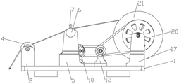
图1为本实用新型一种汽车电线生产用多参数可调整导线打圈机的主视结构示意图。Fig. 1 is a front view structure diagram of a multi-parameter adjustable wire looping machine for automobile electric wire production of the utility model.
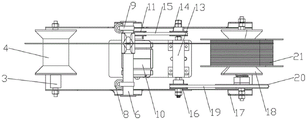
图2为本实用新型一种汽车电线生产用多参数可调整导线打圈机的俯视结构示意图。Fig. 2 is a top view structure schematic diagram of a multi-parameter adjustable wire looping machine for the production of automobile electric wires according to the utility model.
图3为本实用新型一种汽车电线生产用多参数可调整导线打圈机的穿线环三维结构示意图。Fig. 3 is a three-dimensional structure schematic diagram of a threading ring of a multi-parameter adjustable wire looping machine of the utility model for automobile wire production.
图中:1、底板,2、支架,3、第一转轴,4、导向轮,5、支撑架,6、支杆,7、穿线环,8、伸缩推杆,9、移动套,10、电机,11、主动轮,12、固定架,13、旋转轴,14、从动轮,15、第一传送带,16、第一转轮,17、放置架,18、转动辊,19、第二传送带,20、第二转轮,21、收卷盘。Among the figure: 1, bottom plate, 2, bracket, 3, first rotating shaft, 4, guide wheel, 5, support frame, 6, pole, 7, threading ring, 8, telescopic push rod, 9, moving sleeve, 10, Motor, 11, driving wheel, 12, fixed frame, 13, rotating shaft, 14, driven wheel, 15, first conveyor belt, 16, first runner, 17, placement frame, 18, turning roller, 19, second conveyor belt , 20, the second runner, 21, the winding reel.
具体实施方式Detailed ways
基于本实用新型中的实施例,本领域普通技术人员在没有做出创造性劳动前提下所获得的所有其他实施例,都属于本实用新型保护的范围。Based on the embodiments of the present utility model, all other embodiments obtained by persons of ordinary skill in the art without making creative efforts belong to the scope of protection of the present utility model.
请参阅附图1-3,本实用新型提供一种技术方案:一种汽车电线生产用多参数可调整导线打圈机,包括底板1,所述底板1上安装有张力调节收卷结构,所述张力调节收卷结构包括:支架2、第一转轴3、导向轮4、支撑架5、支杆6、穿线环7、一对伸缩推杆8、一对移动套9以及收卷组件;所述支架2安装在所述底板1上壁面,所述第一转轴3套装在所述支架2上,所述导向轮4安装在所述第一转轴3上,所述支撑架5安装在所述底板1上壁面,所述一对伸缩推杆8安装在所述底板1上,所述一对移动套9分别安装在所述一对伸缩推杆8驱动端,所述支杆6安装在所述一对移动套9上且所述支杆6与所述支撑架5接触,所述穿线环7安装在所述支杆6上,所述收卷组件安装在所述底板1上壁面。Please refer to the accompanying drawings 1-3, the utility model provides a technical solution: a multi-parameter adjustable wire looping machine for automobile wire production, including a base plate 1, a tension adjustment winding structure is installed on the base plate 1, the The tension adjustment winding structure includes: a bracket 2, a first rotating
需要说明的是,当需要对电线进行张力调节时,首先电线通过支架2上的导向轮4进行引导,后穿过穿线环7与收卷结构连接,驱动一对伸缩推杆8,一对伸缩推杆8带动支杆6进行移动,安装在支杆6上的穿线环7跟随支杆6进行移动,进而可对电线进行张力调节,张力太小会使控制更加困难,收卷松弛,张力过大可能会导致电线伸长或长度增加。It should be noted that, when it is necessary to adjust the tension of the electric wire, first the electric wire is guided by the guide wheel 4 on the bracket 2, and then passes through the
在具体实施过程中,所述收卷组件包括:电机10、主动轮11、固定架12、旋转轴13、从动轮14、第一传送带15、第一转轮16、放置架17、转动辊18、第二传送带19、第二转轮20以及收卷盘21;In the specific implementation process, the winding assembly includes: a
所述电机10安装在所述底板1上壁面,所述主动轮11安装在所述电机10驱动端,所述固定架12安装在所述底板1上壁面,所述旋转轴13套装在所述固定架12上,所述从动轮14安装在所述旋转轴13一端,所述第一传送带15安装在所述主动轮11以及所述从动轮14上,所述第一转轮16安装在所述旋转轴13另一端,所述放置架17安装在所述底板1上壁面,所述转动辊18安装在所述放置架17上,所述第二转轮20安装在所述转动辊18上,所述第二传送带19安装在所述第一转轮16以及所述第二转轮20上,所述收卷盘21安装在所述转动辊18上;The
需要说明的是,当需要对电线进行收卷时,电线经过引导后与收卷盘21连接,驱动电机10工作,电机10带动主动轮11进行转动,从动轮14在第一传送带15的作用下跟随主动轮11进行转动,旋转轴13在从动轮14的作用下进行转动,第一转轮16跟随旋转轴13进行转动,第二转轮20在第二传送带19以及第一转轮16的作用下开始带动转动辊18进行转动,安装在转动辊18上的收卷盘21同步转动,对电线进行收卷。It should be noted that when the electric wire needs to be wound up, the electric wire is connected to the
在具体实施过程中,进一步的,所述穿线环7上设有开口。In the specific implementation process, further, the
需要说明的是,穿线环7上的开口便于电线穿过,从而方便控制电线张力。It should be noted that the opening on the
在具体实施过程中,进一步的,所述固定架12与所述底板1安装方式为螺栓连接。In a specific implementation process, further, the installation method of the
需要说明的是,螺栓连接便于固定架12的安装与拆卸。It should be noted that the bolt connection facilitates the installation and removal of the
在具体实施过程中,进一步的,所述穿线环7上喷涂有耐磨涂层。In the specific implementation process, further, the wear-resistant coating is sprayed on the
需要说明的是,耐磨涂层提高了穿线环7的耐磨性,增加了使用寿命。It should be noted that the wear-resistant coating improves the wear resistance of the
在具体实施过程中,进一步的,所述底板1下壁面设有垫块。In the specific implementation process, further, cushion blocks are provided on the lower wall of the bottom plate 1 .
需要说明的是,垫块使底板1放置更加稳定。It should be noted that the pads make the placement of the base plate 1 more stable.
尽管已经示出和描述了本实用新型的实施例,对于本领域的普通技术人员而言,可以理解在不脱离本实用新型的原理和精神的情况下可以对这些实施例进行多种变化、修改、替换和变型,本实用新型的范围由所附权利要求及其等同物限定。Although the embodiments of the present invention have been shown and described, those skilled in the art can understand that various changes and modifications can be made to these embodiments without departing from the principle and spirit of the present invention , replacements and modifications, the scope of the present utility model is defined by the appended claims and their equivalents.
Claims (6)
Priority Applications (1)
| Application Number | Priority Date | Filing Date | Title |
|---|---|---|---|
| CN202222371696.1U CN218370937U (en) | 2022-09-07 | 2022-09-07 | A multi-parameter adjustable wire looping machine for automobile wire production |
Applications Claiming Priority (1)
| Application Number | Priority Date | Filing Date | Title |
|---|---|---|---|
| CN202222371696.1U CN218370937U (en) | 2022-09-07 | 2022-09-07 | A multi-parameter adjustable wire looping machine for automobile wire production |
Publications (1)
| Publication Number | Publication Date |
|---|---|
| CN218370937U true CN218370937U (en) | 2023-01-24 |
Family
ID=84971425
Family Applications (1)
| Application Number | Title | Priority Date | Filing Date |
|---|---|---|---|
| CN202222371696.1U Active CN218370937U (en) | 2022-09-07 | 2022-09-07 | A multi-parameter adjustable wire looping machine for automobile wire production |
Country Status (1)
| Country | Link |
|---|---|
| CN (1) | CN218370937U (en) |
-
2022
- 2022-09-07 CN CN202222371696.1U patent/CN218370937U/en active Active
Similar Documents
| Publication | Publication Date | Title |
|---|---|---|
| CN206711676U (en) | A kind of take-up of strand winder | |
| CN110733936A (en) | 3D prints wire winding device | |
| CN204234486U (en) | A kind of power external copper wire drawbench | |
| CN217035265U (en) | Wire and cable stranding machine suitable for multiple wires | |
| CN215770684U (en) | Automatic adhesive tape equipment that twines of wire rod | |
| CN201266517Y (en) | Horizontal lapping device | |
| CN117550423B (en) | A winding machine with an adjustable collection structure diameter | |
| CN221796581U (en) | Cantilever single strander | |
| CN209337869U (en) | A kind of cable winding storage material type tension control mechanism | |
| CN217920753U (en) | Small disc rewinding equipment | |
| CN208790920U (en) | A swing arm type electric lift wire take-up machine | |
| CN2579851Y (en) | Duoble rolling tube continuous winding device | |
| CN110027938A (en) | A kind of portable adjustable tension pay off rack device of outdoor optical cable | |
| CN220449398U (en) | Wire and cable coiling machine | |
| CN220564016U (en) | Tension adjusting device for cable production equipment | |
| CN114160712A (en) | Copper wire winding positioning mechanism | |
| CN220055838U (en) | An I-shaped wheel winding machine | |
| CN221970906U (en) | A cable winding device for production | |
| CN221909108U (en) | Cable production is with electrically conductive silk wire drawing device | |
| CN221657535U (en) | Diamond wire female wire drawing machine | |
| CN221939740U (en) | Cable processing is with pulling coiling device | |
| CN223582754U (en) | Cage type wire twisting machine for wire and cable production | |
| CN221918732U (en) | Strander with direction function | |
| CN219842838U (en) | High-efficient cabling device is used in cable production | |
| CN223728530U (en) | Wire twisting device |
Legal Events
| Date | Code | Title | Description |
|---|---|---|---|
| GR01 | Patent grant | ||
| GR01 | Patent grant | ||
| PE01 | Entry into force of the registration of the contract for pledge of patent right | ||
| PE01 | Entry into force of the registration of the contract for pledge of patent right |
Denomination of utility model: A multi parameter adjustable wire winding machine for automotive wire production Granted publication date: 20230124 Pledgee: Shandong Shanghe Rural Commercial Bank Co.,Ltd. Pledgor: Shandong Lvbao Power Technology Co.,Ltd. Registration number: Y2025980003734 |
|
| CP03 | Change of name, title or address | ||
| CP03 | Change of name, title or address |
Address after: 250000 Shandong Province, Jinan City, Shanghe County, Private Enterprise Industrial Park Patentee after: Shandong Jingbao Cable Technology Co.,Ltd. Country or region after: China Address before: Private Industrial Park, Yuhuangmiao Town, Shanghe County, Jinan City, Shandong Province Patentee before: Shandong Lvbao Power Technology Co.,Ltd. Country or region before: China |