CN218370476U - Blanking device - Google Patents
Blanking device Download PDFInfo
- Publication number
- CN218370476U CN218370476U CN202222074962.4U CN202222074962U CN218370476U CN 218370476 U CN218370476 U CN 218370476U CN 202222074962 U CN202222074962 U CN 202222074962U CN 218370476 U CN218370476 U CN 218370476U
- Authority
- CN
- China
- Prior art keywords
- frame
- discharging
- translation
- transmission
- ejection
- Prior art date
- Legal status (The legal status is an assumption and is not a legal conclusion. Google has not performed a legal analysis and makes no representation as to the accuracy of the status listed.)
- Active
Links
- 238000007599 discharging Methods 0.000 claims abstract description 57
- 238000013519 translation Methods 0.000 claims abstract description 52
- 230000007246 mechanism Effects 0.000 claims abstract description 49
- 239000011521 glass Substances 0.000 claims abstract description 40
- 239000000463 material Substances 0.000 claims abstract description 17
- 230000005540 biological transmission Effects 0.000 claims description 75
- 230000009467 reduction Effects 0.000 claims description 31
- 241000252254 Catostomidae Species 0.000 claims description 6
- 238000005096 rolling process Methods 0.000 claims description 3
- XLYOFNOQVPJJNP-UHFFFAOYSA-N water Substances O XLYOFNOQVPJJNP-UHFFFAOYSA-N 0.000 claims 1
- CDBYLPFSWZWCQE-UHFFFAOYSA-L Sodium Carbonate Chemical compound [Na+].[Na+].[O-]C([O-])=O CDBYLPFSWZWCQE-UHFFFAOYSA-L 0.000 description 2
- 230000008859 change Effects 0.000 description 2
- 238000000034 method Methods 0.000 description 2
- 238000012545 processing Methods 0.000 description 2
- 239000002994 raw material Substances 0.000 description 2
- 235000019738 Limestone Nutrition 0.000 description 1
- 239000006004 Quartz sand Substances 0.000 description 1
- VYPSYNLAJGMNEJ-UHFFFAOYSA-N Silicium dioxide Chemical compound O=[Si]=O VYPSYNLAJGMNEJ-UHFFFAOYSA-N 0.000 description 1
- TZCXTZWJZNENPQ-UHFFFAOYSA-L barium sulfate Chemical compound [Ba+2].[O-]S([O-])(=O)=O TZCXTZWJZNENPQ-UHFFFAOYSA-L 0.000 description 1
- AYJRCSIUFZENHW-DEQYMQKBSA-L barium(2+);oxomethanediolate Chemical compound [Ba+2].[O-][14C]([O-])=O AYJRCSIUFZENHW-DEQYMQKBSA-L 0.000 description 1
- 239000010428 baryte Substances 0.000 description 1
- 229910052601 baryte Inorganic materials 0.000 description 1
- 229910021538 borax Inorganic materials 0.000 description 1
- KGBXLFKZBHKPEV-UHFFFAOYSA-N boric acid Chemical compound OB(O)O KGBXLFKZBHKPEV-UHFFFAOYSA-N 0.000 description 1
- 239000004327 boric acid Substances 0.000 description 1
- 230000008878 coupling Effects 0.000 description 1
- 238000010168 coupling process Methods 0.000 description 1
- 238000005859 coupling reaction Methods 0.000 description 1
- 239000010433 feldspar Substances 0.000 description 1
- 229910052500 inorganic mineral Inorganic materials 0.000 description 1
- 239000006028 limestone Substances 0.000 description 1
- 239000007769 metal material Substances 0.000 description 1
- 238000012986 modification Methods 0.000 description 1
- 230000004048 modification Effects 0.000 description 1
- 230000008569 process Effects 0.000 description 1
- 229910000029 sodium carbonate Inorganic materials 0.000 description 1
- 235000017550 sodium carbonate Nutrition 0.000 description 1
- 239000004328 sodium tetraborate Substances 0.000 description 1
- 235000010339 sodium tetraborate Nutrition 0.000 description 1
- 238000012546 transfer Methods 0.000 description 1
Images



Landscapes
- Intermediate Stations On Conveyors (AREA)
Abstract
The utility model discloses a blanking device, which comprises a feeding mechanism, a material transferring mechanism and a discharging mechanism, wherein the material transferring mechanism comprises a frame, a truss and a translation frame, and the feeding mechanism and the discharging mechanism are respectively arranged under the left side and the right side of the truss; the blanking device is provided with the feeding mechanism, the material transferring mechanism and the discharging mechanism, wherein the sucker is moved to the feeding mechanism by utilizing a truss, a translation frame, a sliding frame, a lifting frame and a sucker of the material transferring mechanism, the glass on the feeding mechanism is sucked, then the glass is transferred to a discharging trolley of the discharging mechanism, and the discharging trolley is output by a discharging motor, so that the automatic blanking of the glass is realized, the integral automation degree is high, the efficiency is high, and the practicability is strong; meanwhile, a plurality of pairs of bearing brackets are arranged on the discharging trolley to bear the glass, so that a plurality of pieces of glass can be stored at one time.
Description
Technical Field
The utility model belongs to the technical field of the glass machinery technique and specifically relates to a blanking device is related to.
Background
The glass is an amorphous inorganic non-metallic material, and is generally prepared by taking various inorganic minerals (such as quartz sand, borax, boric acid, barite, barium carbonate, limestone, feldspar, soda ash and the like) as main raw materials and adding a small amount of auxiliary raw materials; glass need carry out the ejection of compact to glass after the processing is accomplished, then transport to all the other equipment and continue processing or pack and dispatch from the factory, and current glass unloading adopts the manual work to carry glass to the dolly usually, but because the glass specification after the ejection of compact is great, and manual handling is troublesome, consequently needs to develop a unloader that degree of automation is high.
SUMMERY OF THE UTILITY MODEL
Not enough to prior art, the utility model aims to provide a unloader on commodity circulation transfer chain that the practicality is strong, degree of automation is high.
In order to achieve the above purpose, the utility model provides a scheme does: a blanking device comprises a feeding mechanism, a material transferring mechanism and a discharging mechanism, wherein the material transferring mechanism comprises a rack, a truss and a translation frame, the feeding mechanism and the discharging mechanism are respectively arranged under the left side and the right side of the truss, the truss is connected with the translation frame in a sliding manner, a sliding guide rail is arranged on the translation frame, a sliding frame is connected on the sliding guide rail in a sliding manner, a lifting frame is connected on the sliding frame in a sliding manner, the bottom end of the lifting frame is connected with a plurality of suckers, and the suckers are used for jointly sucking glass on the feeding mechanism;
discharge mechanism includes ejection of compact frame, ejection of compact guide rail, ejection of compact dolly, ejection of compact motor, the ejection of compact frame outside sets up ejection of compact guide rail, ejection of compact guide rail extends along ejection of compact frame length direction, sliding connection ejection of compact dolly on the ejection of compact guide rail, ejection of compact motor is used for driving ejection of compact dolly and removes, it is many right to be provided with on the ejection of compact dolly to hold the bracket, it is many right to hold the bracket from top to bottom equidistant arranging, every right it is right to hold the bracket and be used for bearing glass.
The utility model has the advantages that: the automatic blanking of glass is realized, the blanking device is provided with the feeding mechanism, the material transferring mechanism and the discharging mechanism, wherein the sucker is moved to the feeding mechanism by utilizing a truss, a translation frame, a sliding frame, a lifting frame and a sucker of the material transferring mechanism, the glass on the feeding mechanism is sucked, then the glass is transferred to a discharging trolley of the discharging mechanism, and the discharging trolley is output by a discharging motor, so that the automatic blanking of the glass is realized, the integral automation degree is high, the efficiency is high, and the practicability is high; meanwhile, a plurality of pairs of supporting brackets are arranged on the discharging trolley to support the glass, and a plurality of pieces of glass can be stored at one time.
Further, the feeding mechanism comprises a feeding frame and a feeding motor, a transmission shaft and a plurality of conveying rollers are respectively connected to the feeding frame in a rotating mode, the feeding motor is connected with a feeding reduction gearbox, the feeding reduction gearbox is connected with the transmission shaft, a plurality of first driving gears are sleeved on the transmission shaft, a first driven gear is coaxially connected to the end portion of each conveying roller, and the first driving gears are meshed with the first driven gears. The utility model adopts the above structure after, realize driving many conveying rollers and rotate in step.
Furthermore, the tail end of the feeding frame is provided with a baffle, each conveying roller is sleeved with a plurality of conveying wheels, the plurality of conveying wheels are arranged at equal intervals along the length direction of the conveying roller, and the plurality of conveying wheels are used for conveying glass in a rolling mode. The utility model adopts the above structure after to glass is carried in the roll.
Furthermore, a translation guide rail and a first transmission rack are arranged on the truss, the translation guide rail and the first transmission rack extend along the length direction of the truss respectively, a first transmission gear is rotatably connected to the bottom of the translation frame, the first transmission gear is meshed with the first transmission rack, a translation motor is arranged on the translation frame, the translation motor is connected with a translation reduction gearbox, and the translation reduction gearbox is connected with the first transmission gear. The utility model adopts the above structure after, the practice drives translation frame left and right translation.
Furthermore, a pushing hydraulic cylinder is arranged on the translation frame and connected with the sliding frame. The utility model adopts the above structure after, realize driving the carriage back-and-forth movement.
Further, a lifting motor and a lifting guide rail are arranged on the sliding frame, the lifting motor is connected with a lifting reduction gearbox, the lifting reduction gearbox is connected with a second transmission gear, the lifting guide rail extends vertically, the lifting guide rail is connected with a lifting frame in a sliding mode, a second transmission rack is arranged on the lifting frame, the second transmission rack extends along the length direction of the lifting frame, and the second transmission gear is meshed with the second transmission rack. The utility model adopts the above structure after, realize driving the crane and reciprocate.
Furthermore, the discharging motor is connected with a discharging reduction gearbox, the discharging reduction gearbox is connected with a second driving gear, a second driven gear is rotatably connected to the discharging frame, the second driving gear is connected with the second driven gear through a first transmission chain, third transmission gears are rotatably connected to the front side and the rear side of the discharging frame respectively, a second transmission chain is connected between the two third transmission gears, the second transmission chain is connected with the discharging trolley, and the second driven gear is coaxially connected with one of the third transmission gears. The utility model adopts the above structure after, realize driving ejection of compact dolly back-and-forth movement.
Furthermore, two vertical limiting frames are arranged on the discharging trolley, the two limiting frames are respectively positioned on the front side and the rear side of the discharging trolley, and the two limiting frames are used for jointly limiting the glass to exit from the supporting bracket from the front side and the rear side of the supporting bracket.
Drawings
Fig. 1 is a perspective view of the overall structure of the present invention.
Fig. 2 is a perspective view of the whole structure of the present invention.
Fig. 3 is a partially enlarged view of a portion a in fig. 2.
Fig. 4 is a partially enlarged view of fig. 2 at B.
Fig. 5 is a partially enlarged view of fig. 2 at C.
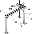
Fig. 6 is a perspective view of the material transferring mechanism of the present invention.
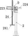
Fig. 7 is a side view of the material transferring mechanism of the present invention.
Fig. 8 is a partially enlarged view of fig. 7 at D.
The automatic feeding device comprises a feeding frame 11, a transmission shaft 12, a first driving gear 121, a conveying roller 13, a first driven gear 131, a conveying wheel 132, a feeding motor 14, a feeding reduction gearbox 141, a baffle 15, a frame 2, a truss 21, a translation guide rail 211, a first transmission rack 212, a translation frame 22, a translation motor 221, a translation reduction gearbox 222, a sliding guide rail 223, a pushing hydraulic cylinder 224, a first transmission gear 225, a sliding frame 23, a lifting guide rail 231, a lifting motor 232, a second transmission gear 233, a lifting frame 24, a suction cup 242, a second transmission rack 242, a discharging frame 31, a second driven gear 311, a third transmission gear 312, a second transmission chain 313, a discharging guide rail 32, a discharging trolley 33, a support bracket 331, a limit bracket 332, a discharging motor 34, a discharging reduction gearbox 341 and a second driving gear 342.
Detailed Description
The invention will be further described with reference to the following specific embodiments:
referring to fig. 1 to 8, a discharging device, including feed mechanism, change material mechanism, discharge mechanism, change material mechanism and include frame 2, truss 21, translation frame 22, feed mechanism includes feeding frame 11, feeding motor 14, it is connected with transmission shaft 12 to rotate respectively on the feeding frame 11, many conveying rollers 13, feeding motor 14 is connected with feeding reducing gear box 141, feeding reducing gear box 141 connects transmission shaft 12, the cover is equipped with a plurality of first driving gears 142 on the transmission shaft 12, 13 end coaxial coupling of conveying roller has first driven gear 131, first driving gear 142 and the meshing of first driven gear 131.
The feeding mechanism and the discharging mechanism are arranged under the left side and the right side of the truss 21 respectively, the translation frame 22 is connected onto the truss 21 in a sliding mode, the sliding guide rail 223 is arranged on the translation frame 22, the sliding guide rail 223 is connected with the sliding frame 23 in a sliding mode, the sliding frame 23 is connected with the lifting frame 24 in a sliding mode, the bottom end of the lifting frame 24 is connected with a plurality of suckers 241, and the suckers 241 are used for sucking glass on the feeding mechanism together.
In this embodiment, the baffle 15 is disposed at the end of the feeding frame 11, a plurality of conveying wheels 132 are sleeved on each conveying roller 13, the plurality of conveying wheels 132 are arranged at equal intervals along the length direction of the conveying roller 13, and the plurality of conveying wheels 132 are used for conveying glass in a rolling manner.
In this embodiment, the truss 21 is provided with a translation guide rail 211 and a first transmission rack 212, the translation guide rail 211 and the first transmission rack 212 extend along the length direction of the truss 21 respectively, the bottom of the translation frame 22 is rotatably connected with a first transmission gear 225, the first transmission gear 225 is engaged with the first transmission rack 212, the translation frame 22 is provided with a translation motor 221, the translation motor 221 is connected with a translation reduction box 222, and the translation reduction box 222 is connected with the first transmission gear 225; the translation frame 22 is provided with a pushing hydraulic cylinder 224, and the pushing hydraulic cylinder 224 is connected with the sliding frame 23.
Discharge mechanism includes ejection of compact frame 31, ejection of compact guide rail 32, ejection of compact dolly 33, ejection of compact motor 34, set up ejection of compact guide rail 32 outside ejection of compact frame 31, ejection of compact guide rail 32 extends along ejection of compact frame 31 length direction, sliding connection ejection of compact dolly 33 on ejection of compact guide rail 32, ejection of compact motor 34 is used for driving ejection of compact dolly 33 and removes, be provided with many pairs of support bracket 331 on the ejection of compact dolly 33, many pairs of support bracket 331 are arranged from top to bottom at equal intervals, every is used for bearing glass to supporting bracket 331.
The discharging motor 34 is connected with a discharging reduction box 341, the discharging reduction box 341 is connected with a second driving gear 342, the discharging frame 31 is rotatably connected with a second driven gear 311, the second driving gear 342 is connected with the second driven gear 311 through a first transmission chain, the front side and the rear side of the discharging frame 31 are respectively rotatably connected with third transmission gears 312, a second transmission chain 313 is connected between the two third transmission gears 312, the second transmission chain 313 is connected with the discharging trolley 33, and the second driven gear 311 is coaxially connected with one of the third transmission gears 312.
In this embodiment, the sliding frame 23 is provided with a lifting motor 232 and a lifting guide rail 231, the lifting motor 232 is connected with a lifting reduction box, the lifting reduction box is connected with a second transmission gear 233, the lifting guide rail 231 extends vertically, the lifting guide rail 231 is connected with the lifting frame 24 in a sliding manner, the lifting frame 24 is provided with a second transmission rack 242, the second transmission rack 242 extends along the length direction of the lifting frame 24, and the second transmission gear 233 is meshed with the second transmission rack 242.
In this embodiment, the discharging trolley 33 is provided with two vertical limiting frames 332, the two limiting frames 332 are respectively located at the front and rear sides of the discharging trolley 33, and the two limiting frames 332 are used for jointly limiting the glass to exit from the support bracket 331 from the front and rear sides of the support bracket 331.
Further, the first driving gear 121 and the first driven gear 131 are both bevel gears.
In this embodiment, the specific blanking process is as follows: firstly, starting a feeding motor 14, driving a feeding reduction gearbox 141 to work by the feeding motor 14, driving a transmission shaft 12 to rotate by the feeding reduction gearbox 141, driving a plurality of first driving gears 121 to rotate by the transmission shaft 12 so as to drive a plurality of first driven gears 131 to synchronously rotate, and driving a plurality of conveying rollers 13 to synchronously rotate, so that glass is conveyed block by block;
until the glass touches the baffle 15, the movement is stopped, at this time, the translation motor 221, the pushing hydraulic cylinder 224 and the lifting motor 232 are respectively started, the translation motor 221 drives the translation reduction box 222 to work, the translation reduction box 222 drives the first transmission gear 225 to rotate, the first transmission gear 225 is meshed with the first transmission rack 212 in a matching mode so as to drive the translation frame 22 to move on the translation guide rail 211 of the truss 21 (to translate in the Y-axis direction), a piston rod of the pushing hydraulic cylinder 224 stretches out and draws back so as to drive the sliding frame 23 to move on the sliding guide rail 223 (to translate in the X-axis direction), the lifting motor 232 drives the lifting reduction box to work, the lifting reduction box drives the second transmission gear 233 to rotate, the second transmission gear 233 is meshed with the second transmission rack 242 so as to drive the lifting frame 24 to move up and down (to move in the Z-axis direction) until a suction cup of the lifting frame 24 moves to the glass positioned on the conveying roller 13 and sucks the glass, the translation motor 221, the pushing hydraulic cylinder 224 and the lifting motor 232 are controlled so as to move the glass to move on the support bracket 331 of the discharging trolley 33, wherein the glass is transversely inserted into the support bracket 331 from the left side and the right side of the discharging trolley 33;
after a set amount of glass is placed on the discharging trolley 33, the discharging motor 34 is started, the discharging motor 34 drives the discharging reduction gearbox 341 to work, the discharging reduction gearbox 341 drives the second driving gear 342 to work, the second driving gear 342 drives the second driven gear 311 to rotate through the first transmission chain, the second driven gear 311 drives one of the third transmission gears 312 to rotate, and the third transmission gear 312 drives the other third transmission gear 312 to rotate through the second transmission chain 313 so as to drive the discharging trolley 33 to move and output the glass.
The above-described embodiments are only preferred embodiments of the present invention, and are not intended to limit the present invention in any way. Those skilled in the art can make further changes and modifications to the invention, or modify equivalent embodiments to equivalent variations, without departing from the scope of the invention. Therefore, the equivalent changes made by the idea of the present invention are all covered in the protection scope of the present invention.
Claims (8)
1. The utility model provides a blanking device, includes feed mechanism, changes material mechanism, discharge mechanism, its characterized in that: the material transferring mechanism comprises a rack (2), a truss (21) and a translation frame (22), wherein a feeding mechanism and a discharging mechanism are respectively arranged under the left side and the right side of the truss (21), the truss (21) is connected with the translation frame (22) in a sliding manner, a sliding guide rail (223) is arranged on the translation frame (22), a sliding frame (23) is connected on the sliding guide rail (223) in a sliding manner, a lifting frame (24) is connected on the sliding frame (23) in a sliding manner, the bottom end of the lifting frame (24) is connected with a plurality of suckers (241), and the suckers (241) are used for jointly sucking glass on the feeding mechanism;
discharge mechanism includes play work or material rest (31), ejection of compact guide rail (32), ejection of compact dolly (33), ejection of compact motor (34), it sets up to go out work or material rest (31) outside ejection of compact guide rail (32), ejection of compact guide rail (32) extend along play work or material rest (31) length direction, sliding connection ejection of compact dolly (33) on ejection of compact guide rail (32), ejection of compact motor (34) are used for driving ejection of compact dolly (33) and remove, be provided with on ejection of compact dolly (33) many to bearing bracket (331), it is many right bearing bracket (331) are from top to bottom equidistant arranging, and are every right bearing bracket (331) are used for bearing glass.
2. The blanking device according to claim 1, characterized in that: the feeding mechanism comprises a feeding frame (11) and a feeding motor (14), a transmission shaft (12) and a plurality of conveying rollers (13) are respectively rotatably connected to the feeding frame (11), the feeding motor (14) is connected with a feeding reduction gearbox (141), the feeding reduction gearbox (141) is connected with the transmission shaft (12), a plurality of first driving gears (142) are sleeved on the transmission shaft (12), a first driven gear (131) is coaxially connected to the end of each conveying roller (13), and the first driving gears (142) are meshed with the first driven gear (131).
3. A blanking unit according to claim 2, characterized in that: the glass conveying device is characterized in that a baffle (15) is arranged at the tail end of the feeding frame (11), a plurality of conveying wheels (132) are sleeved on each conveying roller (13), the plurality of conveying wheels (132) are arranged at equal intervals along the length direction of the conveying rollers (13), and the plurality of conveying wheels (132) are used for conveying glass in a rolling mode.
4. A blanking unit according to claim 3, characterized in that: the truss-type solar water heater is characterized in that a translation guide rail (211) and a first transmission rack (212) are arranged on the truss (21), the translation guide rail (211) and the first transmission rack (212) extend along the length direction of the truss (21) respectively, the bottom of the translation frame (22) is rotatably connected with a first transmission gear (225), the first transmission gear (225) is meshed with the first transmission rack (212), a translation motor (221) is arranged on the translation frame (22), the translation motor (221) is connected with a translation reduction gearbox (222), and the translation reduction gearbox (222) is connected with the first transmission gear (225).
5. A blanking unit according to claim 4, characterized in that: the translation frame (22) is provided with a pushing hydraulic cylinder (224), and the pushing hydraulic cylinder (224) is connected with the sliding frame (23).
6. A blanking unit according to claim 5, characterized in that: be provided with elevator motor (232), lift guide (231) on carriage (23), elevator motor (232) are connected with the lift reducing gear box, the lift reducing gear box is connected with second drive gear (233), vertical extension of lift guide (231), sliding connection crane (24) on lift guide (231), be provided with second driving rack (242) on crane (24), second driving rack (242) extend along crane (24) length direction, second drive gear (233) and second driving rack (242) meshing.
7. The blanking device according to claim 6, characterized in that: the discharging trolley is characterized in that the discharging motor (34) is connected with a discharging reduction box (341), the discharging reduction box (341) is connected with a second driving gear (342), the discharging frame (31) is connected with a second driven gear (311) in a rotating mode, the second driving gear (342) is connected with the second driven gear (311) through a first transmission chain, the front side and the rear side of the discharging frame (31) are respectively connected with a third transmission gear (312) in a rotating mode, a second transmission chain (313) is connected between the two third transmission gears (312), the second transmission chain (313) is connected with the discharging trolley (33), and the second driven gear (311) is coaxially connected with one of the third transmission gears (312).
8. A blanking unit according to claim 7, characterized in that: two vertical limiting frames (332) are arranged on the discharging trolley (33), the two limiting frames (332) are respectively positioned at the front side and the rear side of the discharging trolley (33), and the two limiting frames (332) are used for jointly limiting glass to exit from the supporting bracket (331) from the front side and the rear side of the supporting bracket (331).
Priority Applications (1)
| Application Number | Priority Date | Filing Date | Title |
|---|---|---|---|
| CN202222074962.4U CN218370476U (en) | 2022-08-09 | 2022-08-09 | Blanking device |
Applications Claiming Priority (1)
| Application Number | Priority Date | Filing Date | Title |
|---|---|---|---|
| CN202222074962.4U CN218370476U (en) | 2022-08-09 | 2022-08-09 | Blanking device |
Publications (1)
| Publication Number | Publication Date |
|---|---|
| CN218370476U true CN218370476U (en) | 2023-01-24 |
Family
ID=84965084
Family Applications (1)
| Application Number | Title | Priority Date | Filing Date |
|---|---|---|---|
| CN202222074962.4U Active CN218370476U (en) | 2022-08-09 | 2022-08-09 | Blanking device |
Country Status (1)
| Country | Link |
|---|---|
| CN (1) | CN218370476U (en) |
-
2022
- 2022-08-09 CN CN202222074962.4U patent/CN218370476U/en active Active
Similar Documents
| Publication | Publication Date | Title |
|---|---|---|
| CN108792623B (en) | LCD panel automatic loading and unloading equipment | |
| CN211768283U (en) | Conveying device, conveying equipment and conveying system | |
| CN219097874U (en) | Transmission device for producing and processing water pump fittings | |
| CN219173424U (en) | A transfer structure of a belt conveyor | |
| CN113562371A (en) | Liftable rod box temporary storage device | |
| CN207629209U (en) | A kind of cross axis faces full-automatic grinding lathe | |
| CN213231346U (en) | High-precision multi-layer grabbing and conveying elevator | |
| CN112499953B (en) | Glass cuts processing system | |
| CN115448026A (en) | Novel convertible row embryo machine | |
| CN212528143U (en) | Automatic stripping and slicing device of hollow brick | |
| CN219326313U (en) | Glass piece material loading conveyor | |
| CN217296254U (en) | Small container welding conveying line | |
| CN207224131U (en) | An automatic cutting and rolling shearing system | |
| CN221113041U (en) | Automatic paper feeding equipment | |
| CN219791590U (en) | Soft board buffer memory | |
| CN110540065A (en) | glass transfer device | |
| CN219822852U (en) | Conveying lifting mechanism for automatic cloth roll packaging machine | |
| CN210794731U (en) | Double layer conveying equipment | |
| CN220222707U (en) | Carton unstacking device for full-automatic car loader | |
| CN212639159U (en) | Pick up material upset manipulator | |
| CN208648123U (en) | Copper sheet feeding and conveying device | |
| CN215247900U (en) | Pulsating modular lifting conveying system | |
| CN216271948U (en) | Glass deep processing line | |
| CN223521865U (en) | Glass carrier for door and window production | |
| CN217577157U (en) | Double-layer bidirectional conveyor |
Legal Events
| Date | Code | Title | Description |
|---|---|---|---|
| GR01 | Patent grant | ||
| GR01 | Patent grant |