CN218346246U - Green ecological large-volume structure for treating torrential flood debris flow - Google Patents
Green ecological large-volume structure for treating torrential flood debris flow Download PDFInfo
- Publication number
- CN218346246U CN218346246U CN202222647598.6U CN202222647598U CN218346246U CN 218346246 U CN218346246 U CN 218346246U CN 202222647598 U CN202222647598 U CN 202222647598U CN 218346246 U CN218346246 U CN 218346246U
- Authority
- CN
- China
- Prior art keywords
- flood discharge
- massif
- lateral wall
- outside
- mountain
- Prior art date
- Legal status (The legal status is an assumption and is not a legal conclusion. Google has not performed a legal analysis and makes no representation as to the accuracy of the status listed.)
- Active
Links
Images


Abstract
The utility model provides a green ecological bulky structure of administering mountain torrent mud-rock flow, includes mountain body (1), its characterized in that: the slope of the outside bottom of massif (1) is provided with massif side flood discharge canal lateral wall (3), and the outside of massif side flood discharge canal lateral wall (3) is provided with outside flood discharge canal lateral wall (4), the outside of massif (1) and the upper portion or the upper portion to one side that are located massif side flood discharge canal lateral wall (3) are provided with massif retaining wall (7), and massif side flood discharge canal lateral wall (3), outside flood discharge canal lateral wall (4) or massif retaining wall (7) are along vertically being divided into a plurality of mutually independent layering and pouring district, and this application utilizes engineering technical means to build bulky concrete structures, has adopted the structural style that retaining wall and flood discharge wall combined organic, has both consolidated loose massif structure, has guaranteed the safe flood discharge of ground runoff when the torrential flood discharge again, and it is effectual to manage torrential flood mud flow.
Description
Technical Field
The application relates to a bulky structure, especially relates to a bulky structure of mountain torrent mud-rock flow is administered to green ecology, belongs to civil engineering technical field.
Background
The torrential flood and the debris flow are relatively common mountain disasters, and the torrential flood has the characteristics of sudden outbreak, rapid disaster, concentrated water quantity, large flow velocity and strong scouring destructive power. If the relative height difference is large, a certain gradient exists, a thick soil body exists on the earth surface, debris flow is very easily formed after torrential flood happens under the geological condition of a broken rock layer which is fractured and cut by medium-depth fracture and derivative-grade fracture under the soil body, the torrential flood and the debris flow have huge energy, the torrential flood and the debris flow are fiercely attacked, destructive damage can be caused to infrastructure, the life and property safety of people are seriously threatened, and meanwhile, towns, villages and farmlands can be buried, river channels are blocked, and secondary disasters are caused. Therefore, the treatment of the torrential flood debris flow has important practical significance, and the effective treatment of the torrential flood debris flow is very important especially in important areas where the torrential flood debris flow can burst, such as large-scale residential sites, high-speed railways, national defense engineering facilities and the like.
For a long time, effective technical means are lacked for the management of mountain torrent debris flow in a gravity area, certain effects are achieved on mountain torrents with small relative height difference through modes of reinforcing mountain torrents, arranging flood discharge channels, planting vegetation and the like, but for large mountain torrents with large height difference and mountain torrents with large transverse length, ideal effects cannot be achieved by adopting traditional management means, the resistance to mountain torrents is limited, the surface runoff of the mountain torrents is too large in rainy seasons with heavy rains or continuous rains and heavy rainfall weather caused by strong convection weather, the possibility that the mountain torrent debris flow is caused is still high, and the technical problems cannot be effectively solved all the time.
Disclosure of Invention
The purpose of this application is to the mountain torrent mud-rock flow of current key region administers and lacks effectual technological means always, great to the difference in height, the longer large-scale mountain massif of lateral length adopts the unable effect that reaches the ideal of traditional means of administering, the unable defect and not enough of eliminating of potential safety hazard of the torrent mountain torrent mud-rock flow, the utility model provides an utilize engineering technological means to build bulky concrete structure, the structural style that has adopted retaining wall and flood discharge wall to combine organically, the loose mountain massif structure of texture has both been consolidated, the safe flood discharge of ground runoff when having guaranteed again the torrent, the organizational project of being convenient for is implemented, administer the bulky structure of mountain torrent mud-rock flow to the green ecological management of mountain torrent mud-rock flow effectual.
In order to achieve the purpose, the technical solution of the application is as follows: the utility model provides a green ecological bulky structure of administering mountain torrent mud-rock flow, is including the mountain body that easily forms mountain torrent mud-rock flow geological disasters, the slope of the outside bottom of mountain body is provided with mountain torrent side flood discharge canal lateral wall, and the outside of mountain torrent side flood discharge canal lateral wall is provided with outside flood discharge canal lateral wall, and the level is provided with the flood discharge canal bottom surface between the bottom of mountain torrent side flood discharge canal lateral wall and outside flood discharge canal lateral wall bottom, and mountain torrent side flood discharge canal lateral wall, outside flood discharge canal lateral wall and flood discharge canal bottom surface constitute the flood discharge canal, the outside of mountain body and the upper portion or the upper portion in the slope that are located mountain torrent side flood discharge canal lateral wall are provided with mountain torrent retaining wall, and mountain torrent side flood discharge canal lateral wall, outside flood discharge canal lateral wall or mountain torrent retaining wall divide into a plurality of mutually independent layering along vertical and pour the district, and mountain torrent side flood discharge canal lateral wall, outside flood discharge canal lateral wall and retaining wall set up the construction joint that multichannel vertically runs through.
Furthermore, the bottom surfaces of the side wall of the flood discharge channel on the mountain side, the side wall of the flood discharge channel on the outer side and the bottom surface of the flood discharge channel are provided with gravel cushion layers.
Furthermore, the bottom soil body of the side wall of the mountain side flood discharge channel and the side wall of the outer side flood discharge channel are respectively provided with a bottom foundation for concrete pouring, and the cross section of the flood discharge channel is of an inverted trapezoidal structure.
Furthermore, the mountain side flood discharge channel side wall, the outer side flood discharge channel side wall or the mountain retaining wall is vertically arranged from bottom to top, and the first layered pouring area, the second layered pouring area and the third layered pouring area are arranged.
Furthermore, the soil body in the lateral side of the lateral side wall of the outer flood discharge channel is provided with a retaining wall 8 of the flood discharge channel with a protection and reinforcement effect in an inclined mode.
Furthermore, a construction joint is arranged on the side wall of the mountain side flood discharge channel, the side wall of the outer side flood discharge channel, the mountain retaining wall and the flood discharge channel retaining wall at intervals of 5-30 meters.
Furthermore, be provided with between massif retaining wall and the massif and between flood discharge canal retaining wall and the soil body and backfill the metalling, vertical middle part or the bottom level at backfilling the metalling is provided with prevention of seepage geotechnological cloth, and the upper surface of prevention of seepage geotechnological cloth is provided with the horizontal drain pipe that runs through massif retaining wall or flood discharge canal retaining wall.
The beneficial effect of this application is:
1. this application has adopted massif retaining wall to carry out reliable reinforcement to the loose massif structure of texture to be provided with large-scale flood discharge canal in the outside bottom of massif, the one side that the flood discharge canal is close to the massif is massif side flood discharge canal lateral wall, has guaranteed that the massif surface runoff that the heavy storm leads to can all flow in the flood discharge canal in order.
2. The application builds bulky concrete structure through geotechnical engineering measure to adopted the structural style that retaining wall and flood discharge wall combine organically, and the cooperation resumes the mode of mountain body vegetation and carries out green ecological management to the torrential flood mud-rock flow, can fundamentally solve the potential safety hazard of torrential flood mud-rock flow.
Drawings
Fig. 1 is a schematic structural diagram of a first embodiment of the present application.
Fig. 2 is a schematic structural diagram of a second embodiment of the present application.
Fig. 3 is an enlarged view of the mountain retaining wall of the present application.
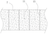
Fig. 4 is a schematic front view of the retaining wall of the present application.
In the figure: in the figure: mountain body 1, bottom basis 2, mountain body side flood discharge channel lateral wall 3, outside flood discharge channel lateral wall 4, flood discharge channel bottom surface 5, rubble bed course 6, mountain body retaining wall 7, flood discharge channel retaining wall 8, prevention of seepage geotechnological cloth 9, backfill rubble layer 10, horizontal drain pipe 11, district 12 is pour in the first layering, district 13 is pour in the second layering, district 14 is pour in the third layering, construction joint 15.
Detailed Description
The present application is described in further detail below with reference to the figures and the detailed description.
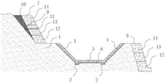
Referring to fig. 1 to 4, the large-volume structure for green ecological management of torrential flood and debris flow comprises a mountain body 1 which is easy to form geological disasters of torrential flood and debris flow, and is characterized in that: the slope of mountain body 1's outside bottom is provided with mountain body side flood discharge canal lateral wall 3, and the outside of mountain body side flood discharge canal lateral wall 3 is provided with outside flood discharge canal lateral wall 4, and the level is provided with flood discharge canal bottom surface 5 between the bottom of mountain body side flood discharge canal lateral wall 3 and outside flood discharge canal lateral wall 4 bottom, and mountain body side flood discharge canal lateral wall 3, outside flood discharge canal lateral wall 4 and flood discharge canal bottom surface 5 constitute the flood discharge canal, the outside of mountain body 1 and the upper portion or the oblique upper portion that are located mountain body side flood discharge canal lateral wall 3 are provided with mountain body retaining wall 7, and mountain body side flood discharge canal lateral wall 3, outside flood discharge canal lateral wall 4 or mountain body wall 7 are vertically divided into a plurality of mutually independent layering along pouring area, and mountain body side flood discharge canal lateral wall 3, outside flood discharge canal lateral wall 4 and mountain body retaining wall 7 set up the construction joint 15 that the multichannel vertically link up the distribution.
The bottom surfaces of the side wall 3 of the mountain flood discharge channel, the side wall 4 of the outer flood discharge channel and the bottom surface 5 of the flood discharge channel are provided with gravel cushion layers 6.
The bottom soil body of mountain side flood discharge channel lateral wall 3 and outside flood discharge channel lateral wall 4 is provided with concrete placement's bottom basis 2 respectively, and the cross section of flood discharge channel is for falling the trapezium structure.
The side flood discharge channel side wall 3 of the mountain body, the side flood discharge channel side wall 4 of the outer side or the retaining wall 7 of the mountain body are cast in a first layered casting area 12, a second layered casting area 13 and a third layered casting area 14 from bottom to top in the longitudinal direction.
The soil body in the 4 outsides in outside flood discharge canal lateral walls inclines upward to be provided with flood discharge canal retaining wall 8 that plays the protection and reinforcement effect.
And a construction joint 15 is arranged on the mountain side flood discharge channel side wall 3, the outer side flood discharge channel side wall 4, the mountain retaining wall 7 and the flood discharge channel retaining wall 8 at an interval of 5-30 meters.
Be provided with between massif retaining wall 7 and the massif 1 and between flood discharge canal retaining wall 8 and the soil body and backfill rubble layer 10, be provided with prevention of seepage geotechnological cloth 9 at vertical middle part or the bottom level of backfilling rubble layer 10, the upper surface of prevention of seepage geotechnological cloth 9 is provided with the horizontal drain pipe 11 that runs through massif retaining wall 7 or flood discharge canal retaining wall 8.
Referring to fig. 1, the present application is directed to a mountain structure with a large height difference and a large transverse length, which is prone to flood debris flow, and there are important infrastructures such as roads and bridges, towns, villages, and important facilities near or at the downstream of the mountain, and there are many mountain areas requiring preventive treatment of flood debris flow nationwide. The application builds bulky concrete structure through geotechnical engineering measure to adopted the structural style that retaining wall and flood discharge wall combine organically, and the cooperation resumes the mode of mountain body vegetation and carries out green ecological management to the torrential flood mud-rock flow, can fundamentally solve the potential safety hazard of torrential flood mud-rock flow. The concrete structure is as follows:
excavate and arrange in order in massif 1's outside bottom, for building massif retaining wall 7, flood discharge channel creation construction conditions, the slope of massif 1's outside bottom is provided with massif side flood discharge channel lateral wall 3, and the outside of massif side flood discharge channel lateral wall 3 is provided with outside flood discharge channel lateral wall 4, and massif side flood discharge channel lateral wall 3 and outside flood discharge channel lateral wall 4 can the symmetry set up, also can the asymmetric setting. The level is provided with flood discharge canal bottom surface 5 between mountain side flood discharge canal lateral wall 3's bottom and outside flood discharge canal lateral wall 4 bottoms, mountain side flood discharge canal lateral wall 3, outside flood discharge canal lateral wall 4 and flood discharge canal bottom surface 5 constitute the flood discharge canal, the cross section of flood discharge canal is for falling the trapezium structure, the degree of depth of flood discharge canal is more than 5 meters, the height and the width of flood discharge canal design according to the biggest flood discharge in this regional torrential rain flood season, form large-scale flood discharge canal, make the ground runoff can carry out in order dredging during the heavy storm.
This application is provided with massif retaining wall 7 in the outside of massif 1, and massif retaining wall 7 not only can play the soil conservation fixed action to the upper portion or the middle part of massif, can also carry out certain guard action to massif side flood discharge canal lateral wall 3, avoids a large amount of water ground runoff of soil stone to enter into the flood discharge canal in, and fundamentally has avoided the torrent to incline from massif upper portion and has just led to the mud-rock flow calamity down. Mountain retaining wall 7 is located the upper portion or the oblique upper portion of mountain side flood discharge canal lateral wall 3, also can be located mountain side flood discharge canal lateral wall 3 upper end outside and be close to one side of mountain promptly mountain retaining wall 7 can be located mountain side flood discharge canal lateral wall 3, has the step of certain width between the lower extreme outside of mountain retaining wall 7 and the upper end of mountain side flood discharge canal lateral wall 3, is similar to the terraced field structure. In addition, the soil body outside the lateral flood discharge channel side wall 4 is provided with the flood discharge channel retaining wall 8 with the protection and reinforcement functions in an inclined mode, and even if the lateral flood discharge channel side wall 4 is located on a mountain, the safety of the flood discharge channel can be guaranteed.
Because the flood discharge channel is a mass concrete structure and has heavier weight, the soil bodies at the bottom of the lateral wall 3 of the flood discharge channel at the mountain side and the lateral wall 4 of the flood discharge channel at the outer side are respectively provided with a bottom foundation 2 poured with concrete, and the grade of the concrete is not lower than C20. Meanwhile, the bottom surfaces of the side wall 3 of the flood discharge channel on the mountain side, the side wall 4 of the flood discharge channel on the outer side and the bottom surface 5 of the flood discharge channel are provided with gravel cushion layers 6, and the gravel cushion layers 6 are used as a foundation.
More importantly, mountain side flood discharge canal lateral wall 3, outside flood discharge canal lateral wall 4 and mountain retaining wall 7 that this application adopted belong to bulky concrete, produce the crack easily, and the crack is bulky concrete structure ubiquitous problem, and wholeness, durability, impermeability and the security of engineering can be endangered to these cracks, for this application has adopted the mode of layering pouring, follows vertical upward from the bottom up and divide into a plurality of districts of pouring, for example: when the mountain retaining wall 7 is of a three-layer casting structure, the mountain retaining wall 7 can be cast in the first layer casting area 12, the second layer casting area 13 and the third layer casting area 14 from bottom to top in the longitudinal direction, and during construction, the layer casting area of the upper layer can be cast only after the layer casting area of the lower layer is solidified. In addition, a plurality of construction joints 15 which are longitudinally communicated and distributed are arranged on the side wall 3 of the mountain flood discharge channel, the side wall 4 of the outer flood discharge channel and the retaining wall 7 of the mountain, the construction joints 15 are used for providing deformation space for concrete when the concrete expands with heat and contracts with cold, and one construction joint 15 is arranged at intervals of 5-30 meters.
Be provided with between massif retaining wall 7 and the massif 1 and between flood discharge canal retaining wall 8 and the soil body and backfill the metalling 10, vertical middle part or the bottom level at backfill metalling 10 are provided with prevention of seepage geotechnological cloth 9, the upper surface of prevention of seepage geotechnological cloth 9 is provided with the horizontal drain pipe 11 that runs through massif retaining wall 7 or flood discharge canal retaining wall 8, the one end parcel that drain pipe 11 is located metalling 10 has the geotechnological cloth that plays filtering action, drain pipe 11 discharges the rainwater between massif retaining wall 7 and the massif 1, it causes adverse effect to massif retaining wall 7 to have avoided long-time ponding. Meanwhile, vegetation can be planted on the surface between the mountain retaining wall 7 and the mountain 1, and vegetation coverage is increased on the surface of the mountain 1 near the mountain retaining wall 7, so that water and soil loss can be prevented, and a certain greening effect can be achieved.
The foregoing is a detailed description of the present application with reference to specific embodiments, and the specific embodiments of the present application are not considered to be limited to the description, and it will be apparent to those skilled in the art that the present application may be embodied with various changes, modifications and variations without departing from the inventive concept of the present application, and the appended claims are intended to cover all such changes, modifications and variations as fall within the true spirit and scope of the present application.
Claims (7)
1. The utility model provides a green ecological management mountain torrent mud-rock flow's bulky structure, includes mountain body (1) that easily forms mountain torrent mud-rock flow geological disasters, its characterized in that: the slope of the outside bottom of massif (1) is provided with massif side flood discharge canal lateral wall (3), and the outside of massif side flood discharge canal lateral wall (3) is provided with outside flood discharge canal lateral wall (4), and the bottom of massif side flood discharge canal lateral wall (3) and level are provided with flood discharge canal bottom surface (5) between outside flood discharge canal lateral wall (4) bottom, and massif side flood discharge canal lateral wall (3), outside flood discharge canal lateral wall (4) and flood discharge canal bottom surface (5) constitute the flood discharge canal, the outside of massif (1) and the upper portion or the upper portion to one side that are located massif side flood discharge canal lateral wall (3) are provided with massif retaining wall (7), and massif side flood discharge canal lateral wall (3), outside flood discharge canal lateral wall (4) or massif retaining wall (7) are divided into a plurality of mutually independent layering pouring district along vertical, and set up the construction joint (15) that vertically link up the distribution in massif side discharge canal lateral wall (3), outside flood discharge canal lateral wall (4) and massif retaining wall (7).
2. The green ecological structure for treating torrential flood and debris flow as claimed in claim 1, wherein: the bottom surfaces of the mountain side flood discharge channel side wall (3), the outer side flood discharge channel side wall (4) and the flood discharge channel bottom surface (5) are provided with gravel cushion layers (6).
3. The green ecological structure for treating torrential flood and debris flow as claimed in claim 1, wherein: the bottom soil body of mountain side flood discharge canal lateral wall (3) and outside flood discharge canal lateral wall (4) is provided with concrete placement's bottom basis (2) respectively, and the cross section of flood discharge canal is for falling the trapezium structure.
4. The green ecological structure for treating torrential flood and debris flow according to claim 1, wherein the structure comprises: district (12), second layering pouring district (13) and third layering pouring district (14) are pour to mountain side flood discharge canal lateral wall (3), outside flood discharge canal lateral wall (4) or mountain retaining wall (7) along vertically upwards from the bottom up for the first layering.
5. The green ecological structure for treating torrential flood and debris flow according to claim 1, wherein the structure comprises: the soil body in outside flood discharge canal lateral wall (4) outside slopes to be provided with flood discharge canal retaining wall (8) that play the protection reinforcement effect.
6. The green ecological structure for treating torrential flood and debris flow according to claim 1, wherein the structure comprises: the mountain side flood discharge channel is provided with a construction joint (15) at intervals of 5-30 meters on mountain side flood discharge channel lateral wall (3), outside flood discharge channel lateral wall (4), mountain retaining wall (7) and flood discharge channel retaining wall (8).
7. The green ecological structure for treating torrential flood and debris flow according to claim 1, wherein the structure comprises: be provided with between massif retaining wall (7) and massif (1) and between flood discharge canal retaining wall (8) and the soil body and backfill rubble layer (10), be provided with prevention of seepage geotechnological cloth (9) at the vertical middle part or the bottom level of backfilling rubble layer (10), the upper surface of prevention of seepage geotechnological cloth (9) is provided with horizontal drain pipe (11) that run through massif retaining wall (7) or flood discharge canal retaining wall (8).
Priority Applications (1)
| Application Number | Priority Date | Filing Date | Title |
|---|---|---|---|
| CN202222647598.6U CN218346246U (en) | 2022-10-09 | 2022-10-09 | Green ecological large-volume structure for treating torrential flood debris flow |
Applications Claiming Priority (1)
| Application Number | Priority Date | Filing Date | Title |
|---|---|---|---|
| CN202222647598.6U CN218346246U (en) | 2022-10-09 | 2022-10-09 | Green ecological large-volume structure for treating torrential flood debris flow |
Publications (1)
| Publication Number | Publication Date |
|---|---|
| CN218346246U true CN218346246U (en) | 2023-01-20 |
Family
ID=84895160
Family Applications (1)
| Application Number | Title | Priority Date | Filing Date |
|---|---|---|---|
| CN202222647598.6U Active CN218346246U (en) | 2022-10-09 | 2022-10-09 | Green ecological large-volume structure for treating torrential flood debris flow |
Country Status (1)
| Country | Link |
|---|---|
| CN (1) | CN218346246U (en) |
-
2022
- 2022-10-09 CN CN202222647598.6U patent/CN218346246U/en active Active
Similar Documents
| Publication | Publication Date | Title |
|---|---|---|
| CN105421485B (en) | Construction method of high-fill prefabricated cast-in-situ combined pile slab wall protection structure | |
| CN103510441B (en) | Three-dimensional-drainage roadbed structure for preventing water damage of road in cold region and construction method thereof | |
| CN106836275A (en) | Landscape eco-friendly retaining wall for rapidly protecting tillite slope and implementation method | |
| CN109736141A (en) | The anti-freeze expansion structural body and paving method of Railway Roadbed in Permafrost Regions | |
| CN111335100A (en) | Embankment structure suitable for coastal region and construction method thereof | |
| CN112392127B (en) | Dendritic embedded type flexible ecological slope drainage ditch and construction method | |
| CN101914882B (en) | Low embankment structure in phreatic high slity soil region and construction method thereof | |
| CN203498721U (en) | Three-dimensional drainage roadbed structure preventing damage by water of road in cold region | |
| CN109826065B (en) | High-fill roadbed protection system and construction method thereof | |
| CN210216254U (en) | Concrete guardrail structure | |
| CN108532406A (en) | Can rapid construction high-bearing capacity pervious surface and laying method | |
| CN110984193A (en) | Severe cold mountain area highway cutting side slope ecological protection system | |
| CN106759778A (en) | For the scattered collection mating type waterproof and water drainage system of highway median strip | |
| CN210596858U (en) | Plateau permafrost region roadbed structure | |
| CN208748462U (en) | Can rapid construction high-bearing capacity pervious surface | |
| CN218346246U (en) | Green ecological large-volume structure for treating torrential flood debris flow | |
| CN206503213U (en) | Scattered collection mating type waterproof and water drainage system for highway median strip | |
| CN216515520U (en) | Underground drainage structure of high-fill engineering in water-rich area | |
| CN214882662U (en) | Special roadbed structure above subway | |
| CN214363925U (en) | Cut water seepage ditch system | |
| CN209873822U (en) | Cutting slope slobbering ice protective structure | |
| CN210262542U (en) | Road structure for sponge city construction | |
| CN209010891U (en) | A kind of multi-functional lobby drainage facility | |
| CN209873485U (en) | Permanent temporary combined toilet structure for gully treatment | |
| CN109403356B (en) | Side slope supporting structure |
Legal Events
| Date | Code | Title | Description |
|---|---|---|---|
| GR01 | Patent grant | ||
| GR01 | Patent grant |