CN218342477U - Wet-mixed mortar mixer - Google Patents
Wet-mixed mortar mixer Download PDFInfo
- Publication number
- CN218342477U CN218342477U CN202222569841.7U CN202222569841U CN218342477U CN 218342477 U CN218342477 U CN 218342477U CN 202222569841 U CN202222569841 U CN 202222569841U CN 218342477 U CN218342477 U CN 218342477U
- Authority
- CN
- China
- Prior art keywords
- fixed
- mortar
- sand mixer
- wet
- motor
- Prior art date
- Legal status (The legal status is an assumption and is not a legal conclusion. Google has not performed a legal analysis and makes no representation as to the accuracy of the status listed.)
- Active
Links
- 239000004570 mortar (masonry) Substances 0.000 title claims abstract description 66
- 239000004576 sand Substances 0.000 claims abstract description 44
- 230000005540 biological transmission Effects 0.000 claims abstract description 4
- 230000009471 action Effects 0.000 claims description 10
- 230000007246 mechanism Effects 0.000 claims description 7
- 244000309464 bull Species 0.000 claims description 6
- 230000000149 penetrating effect Effects 0.000 claims description 4
- 238000007599 discharging Methods 0.000 abstract description 9
- 208000034189 Sclerosis Diseases 0.000 abstract 1
- 238000000034 method Methods 0.000 description 8
- 238000003756 stirring Methods 0.000 description 6
- 230000008569 process Effects 0.000 description 5
- 239000000203 mixture Substances 0.000 description 4
- 239000000463 material Substances 0.000 description 3
- 239000002699 waste material Substances 0.000 description 2
- 239000000853 adhesive Substances 0.000 description 1
- 230000001070 adhesive effect Effects 0.000 description 1
- 230000004075 alteration Effects 0.000 description 1
- 230000009286 beneficial effect Effects 0.000 description 1
- 239000004927 clay Substances 0.000 description 1
- 238000004140 cleaning Methods 0.000 description 1
- 230000000694 effects Effects 0.000 description 1
- 238000005516 engineering process Methods 0.000 description 1
- 238000000227 grinding Methods 0.000 description 1
- 238000004519 manufacturing process Methods 0.000 description 1
- 238000012986 modification Methods 0.000 description 1
- 230000004048 modification Effects 0.000 description 1
- 239000003110 molding sand Substances 0.000 description 1
- 238000005096 rolling process Methods 0.000 description 1
- 238000006467 substitution reaction Methods 0.000 description 1
Images



Landscapes
- Preparation Of Clay, And Manufacture Of Mixtures Containing Clay Or Cement (AREA)
Abstract
The utility model relates to the technical field of sand mixer processing, and discloses a wet-mixed mortar and sand mixer, which comprises a base, the top of the base is fixed with vertical plates in pairs, two vertical plates are rotatably connected with a sand mixer tank body, one side of the top of the base is provided with a first motor, an output shaft of the first motor is fixed with a driving wheel, a driven wheel is fixed on a rotating shaft at one side of the sand mixer tank body, the driven wheel is connected with the driving wheel through a belt transmission, and a transverse plate is fixed at the top of the sand mixer tank body; the utility model discloses can accelerate the ejection of compact speed of mortar, improve the discharging efficiency of mortar, can also clear away the mortar of remaining on the bucket wall, not only improve the collection rate of mortar, still ensure the subsequent normal use of roller mill, solve present roller mill when using, the sclerosis appears at a slow easy time of mortar ejection of compact speed, and the incomplete partial mortar of the mortar ejection of compact can adhere the problem on the bucket wall.
Description
Technical Field
The utility model relates to a roller mill processing technology field specifically is a wet mixture mixed mortar roller mill.
Background
The sand mixer is a device capable of rolling, grinding and crushing materials, can mix the materials while crushing the materials, is widely used for mixing molding sand with clay as an adhesive, can ensure the uniform and consistent sand mixing effect and improve the sand mixing efficiency, is usually used in the production of wet-mixed mortar, and can process and trial-prepare the mortar.
When wet-mixed mortar is produced, a sand mixer needs to be used for wet-mixed processing, the sand mixer needs to discharge the mortar after processing, and when the existing sand mixer discharges the mortar, because a discharge port is small, the discharging speed of the mortar is low, the mortar on the upper layer is easy to harden when contacting with air, the discharging of the mortar is incomplete, part of the mortar can be adhered to the barrel wall of the sand mixer, so that the mortar is wasted, and meanwhile, the mortar can be solidified on the barrel wall if not cleaned in time, and the subsequent use of the sand mixer can be influenced.
SUMMERY OF THE UTILITY MODEL
An object of the utility model is to provide a wet mixture mortar roller mill, can accelerate the ejection of compact speed of mortar, improved the discharging efficiency of mortar, can also clear away the mortar of remaining on the bucket wall, not only improve the collection rate of mortar, still ensured the subsequent normal use of roller mill, solved present roller mill when using, the hardening appears at a slow easy time in mortar ejection of compact speed, and the incomplete partial mortar of mortar ejection of compact can the problem of adhesion on the bucket wall.
In order to achieve the above object, the utility model provides a following technical scheme: the utility model provides a wet mixture mortar roller mill, includes the base, the top of base is fixed with the riser in pairs, two it is connected with the roller mill jar body to rotate between the riser, first motor is installed to one side at base top, the output shaft of first motor is fixed with the action wheel, the axis of rotation of roller mill jar body one side is fixed with from the driving wheel, be connected through belt transmission between driving wheel and the action wheel, the top of the roller mill jar body is fixed with the diaphragm, rabbling mechanism is installed at the top of diaphragm, the inside of the roller mill jar body is provided with the ring, the both sides of ring all are fixed with the dead lever in pairs, the other end of dead lever is fixed with the scraper blade, the inner wall swing joint of scraper blade and the roller mill jar body, the top of scraper blade is fixed with the straight-bar, the straight-bar runs through the surface of diaphragm and rather than run through department swing joint, the top of straight-bar is fixed with the board of folding, the top of board is fixed with the handle.
Preferably, the rabbling mechanism includes the casing, the internally mounted of casing has the second motor, the output shaft of second motor is fixed with the bull stick, the bull stick runs through to the inside of the sand mixer jar body and rotates rather than the inner wall and be connected, the fixed surface of bull stick has a plurality of puddlers.
Preferably, the surface of the vertical plate is provided with a sliding groove, the inside of the sliding groove is connected with a sliding block in a sliding manner, one end of the sliding block is fixed with a connecting rod, and the other end of the connecting rod is fixed with the surface of the sand mixer tank body.
Preferably, both sides of the sand mixer tank body are provided with screw holes, bolts penetrate through the surface of the folding plate, the bolts are movably connected with the penetrating positions of the folding plate, and the bolts are matched with the screw holes for use.
Preferably, a hand wheel is fixed at one end of the bolt.
Preferably, the scraper is designed in an arc shape, and the scraper is tightly attached to the inner wall of the sand mixer tank under the action of the circular ring.
Compared with the prior art, the beneficial effects of the utility model are as follows:
the utility model discloses can accelerate the ejection of compact speed of mortar, prevent that the mortar that is located the upper strata from contacting with the air and appearing hardening, the discharging efficiency of mortar is improved, and can also clear away the mortar of remaining on the bucket wall, thereby prevent that the mortar adhesion from causing the waste of mortar on the bucket wall of roller mill, simultaneously through the cleaing away of remaining mortar on the bucket wall, the collection rate of mortar has not only been improved, still ensured the subsequent normal use of roller mill, current roller mill when using has been solved, the hardening appears easily at a slow speed in the mortar ejection of compact, and the incomplete partial mortar of the mortar ejection of compact can the problem of adhesion on the bucket wall.
Drawings
FIG. 1 is a schematic perspective view of the present invention;
FIG. 2 is a schematic perspective view of the present invention;
FIG. 3 is a schematic view of the partial three-dimensional cross-sectional structure of the present invention;
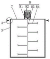
FIG. 4 is a schematic view of the partial cross-sectional structure of the present invention;
FIG. 5 is a schematic view of a partial three-dimensional structure of the present invention;
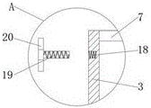
fig. 6 is an enlarged schematic view of a portion a in fig. 4 according to the present invention.
In the figure: 1. a base; 2. a vertical plate; 3. a sand mixer tank body; 4. a first motor; 5. a driving wheel; 6. a driven wheel; 7. a transverse plate; 8. a stirring mechanism; 81. a housing; 82. a second motor; 83. a rotating rod; 84. a stirring rod; 9. a circular ring; 10. a fixing rod; 11. a squeegee; 12. a straight rod; 13. folding the template; 14. a handle; 15. a chute; 16. a slider; 17. a connecting rod; 18. a screw hole; 19. a bolt; 20. a handwheel.
Detailed Description
The technical solutions in the embodiments of the present invention will be described clearly and completely with reference to the accompanying drawings in the embodiments of the present invention, and it is obvious that the described embodiments are only some embodiments of the present invention, not all embodiments. Based on the embodiments in the present invention, all other embodiments obtained by a person skilled in the art without creative efforts all belong to the protection scope of the present invention.
Referring to fig. 1-6, a wet-mixed mortar mixer comprises a base 1, wherein vertical plates 2 are fixed on the top of the base 1 in pairs, a sand mixer tank 3 is rotatably connected between the two vertical plates 2, a first motor 4 is installed on one side of the top of the base 1, a driving wheel 5 is fixed on an output shaft of the first motor 4, a driven wheel 6 is fixed on a rotating shaft on one side of the sand mixer tank 3, the driven wheel 6 is connected with the driving wheel 5 through a belt in a transmission manner, a transverse plate 7 is fixed on the top of the sand mixer tank 3, a stirring mechanism 8 is installed on the top of the transverse plate 7, a circular ring 9 is arranged inside the sand mixer tank 3, fixing rods 10 are fixed on both sides of the circular ring 9 in pairs, a scraper 11 is fixed on the other end of the fixing rod 10, the scraper 11 is movably connected with the inner wall of the sand mixer tank 3, a straight rod 12 is fixed on the top of the scraper 11, the straight rod 12 penetrates through the surface of the transverse plate 7 and is movably connected with the penetrating position of the transverse plate, the top of the straight rod 12 is fixed with the folding plate 13, the top of the folding plate 13 is fixed with the handle 14, the sand mixer can accelerate the discharging speed of mortar, the mortar on the upper layer is prevented from being hardened due to contact with air, the discharging efficiency of the mortar is improved, the mortar remained on the barrel wall can be removed, the mortar is prevented from being adhered to the barrel wall of the sand mixer to cause waste of the mortar, meanwhile, the mortar is removed through the residual mortar on the barrel wall, the collecting rate of the mortar is improved, the subsequent normal use of the sand mixer is ensured, and the problems that when the conventional sand mixer is used, the mortar is low in discharging speed and easy to be hardened, and the mortar can be adhered to the barrel wall due to incomplete discharging of the mortar.
The stirring mechanism 8 comprises a shell 81, a second motor 82 is installed inside the shell 81, a rotating rod 83 is fixed on an output shaft of the second motor 82, the rotating rod 83 penetrates through the inside of the sand mixer tank 3 and is connected with the inner wall of the sand mixer tank in a rotating mode, a plurality of stirring rods 84 are fixed on the surface of the rotating rod 83, in the embodiment, when the sand mixer is actually used, the second motor 82 is started firstly, the output shaft of the second motor 82 drives the rotating rod 83 to rotate, the stirring rods 84 are driven to rotate together, and therefore mortar is mixed and stirred.
The screw holes 18 are formed in the two sides of the sand mixer tank body 3, the bolts 19 penetrate through the surface of the folding plate 13, the bolts 19 are movably connected with the penetrating positions of the folding plate 13, the bolts 19 are matched with the screw holes 18 for use, in the embodiment, the bolts 19 are firstly aligned to the screw holes 18 through the arrangement of the screw holes 18 and the bolts 19, then the bolts 19 are rotated to enter the inside of the screw holes 18, the folding plate 13 can be fixed, and when the cleaning assembly needs to be used, the bolts 19 can be rotated reversely, so that the fixing of the folding plate 13 is released.
A hand wheel 20 is fixed at one end of the bolt 19, and in the embodiment, the hand wheel 20 is arranged, so that the bolt 19 can be driven to rotate together when the hand wheel 20 is rotated, and the force application rotation of workers is facilitated.
The scraper 11 is designed to be arc-shaped, and the scraper 11 is tightly adhered to the inner wall of the sand mixer tank 3 under the action of the ring 9.
The working principle is as follows: in the working process, after the mortar processing is finished, the first motor 4 is started at first, the output shaft of the first motor 4 drives the driving wheel 5 connected through the belt and the driven wheel 6 to rotate together, the sand mixer tank body 3 is made to rotate, the mortar in the tank is poured into the collecting device, when the mortar is about to finish pouring, the tank body can stop rotating, a certain inclination angle is kept, then the bolt 19 is rotated, the fixing of the folding plate 13 is released, then a worker can pull the handle 14 and drive the straight rod 12 to move, and simultaneously the circular ring 9 and the scraper 11 are driven to move together, so that the residual mortar on the inner wall of the sand mixer tank body 3 is scraped and falls into the collecting device.
It should be noted that, in this document, relational terms such as first and second, and the like are used solely to distinguish one entity or action from another entity or action without necessarily requiring or implying any actual such relationship or order between such entities or actions. Also, the terms "comprises," "comprising," or any other variation thereof, are intended to cover a non-exclusive inclusion, such that a process, method, article, or apparatus that comprises a list of elements does not include only those elements but may include other elements not expressly listed or inherent to such process, method, article, or apparatus. Without further limitation, an element defined by the phrases "comprising one of 8230; \8230;" 8230; "does not exclude the presence of additional like elements in a process, method, article, or apparatus that comprises the element.
Although embodiments of the present invention have been shown and described, it will be appreciated by those skilled in the art that changes, modifications, substitutions and alterations can be made in these embodiments without departing from the principles and spirit of the invention, the scope of which is defined in the appended claims and their equivalents.
Claims (6)
1. The utility model provides a wet-mixed mortar roller mill, includes base (1), its characterized in that: the top of base (1) is fixed with riser (2) in pairs, two it is connected with sand mixer jar body (3) to rotate between riser (2), first motor (4) are installed to one side at base (1) top, the output shaft of first motor (4) is fixed with action wheel (5), the axis of rotation of sand mixer jar body (3) one side is fixed with from driving wheel (6), be connected through belt transmission between follow driving wheel (6) and action wheel (5), the top of sand mixer jar body (3) is fixed with diaphragm (7), rabbling mechanism (8) are installed at the top of diaphragm (7), the inside of sand mixer jar body (3) is provided with ring (9), the both sides of ring (9) all are fixed with dead lever (10) in pairs, the other end of dead lever (10) is fixed with scraper blade (11), scraper blade (11) and the inner wall swing joint of sand mixer jar body (3), the top of scraper blade (11) is fixed with straight-bar (12), straight-bar (12) runs through the surface of diaphragm (7) and runs through rather than the department swing joint, the top of straight-bar (12) is fixed with folding plate (13), there is the top of straight-bar (13) the top is fixed with folding plate (13).
2. The wet-mixed mortar mixer according to claim 1, wherein: rabbling mechanism (8) include casing (81), the internally mounted of casing (81) has second motor (82), the output shaft of second motor (82) is fixed with bull stick (83), bull stick (83) run through to the inside of the roller mill jar body (3) and rotate rather than the inner wall and be connected, the fixed surface of bull stick (83) has a plurality of puddlers (84).
3. The wet-mixed mortar mixer according to claim 1, wherein: the surface of the vertical plate (2) is provided with a sliding groove (15), the sliding groove (15) is connected with a sliding block (16) in a sliding manner, one end of the sliding block (16) is fixed with a connecting rod (17), and the other end of the connecting rod (17) is fixed with the surface of the sand mixer tank body (3).
4. A wet mix mortar mixer according to claim 1, characterized in that: screw holes (18) are formed in the two sides of the sand mixer tank body (3), bolts (19) penetrate through the surface of the folding plate (13), the bolts (19) are movably connected with the penetrating positions of the folding plate (13), and the bolts (19) are matched with the screw holes (18) for use.
5. The wet-mixed mortar mixer according to claim 4, wherein: and a hand wheel (20) is fixed at one end of the bolt (19).
6. The wet-mixed mortar mixer according to claim 1, wherein: the scraper (11) is designed in an arc shape, and the scraper (11) is tightly attached to the inner wall of the sand mixer tank body (3) under the action of the circular ring (9).
Priority Applications (1)
| Application Number | Priority Date | Filing Date | Title |
|---|---|---|---|
| CN202222569841.7U CN218342477U (en) | 2022-09-28 | 2022-09-28 | Wet-mixed mortar mixer |
Applications Claiming Priority (1)
| Application Number | Priority Date | Filing Date | Title |
|---|---|---|---|
| CN202222569841.7U CN218342477U (en) | 2022-09-28 | 2022-09-28 | Wet-mixed mortar mixer |
Publications (1)
| Publication Number | Publication Date |
|---|---|
| CN218342477U true CN218342477U (en) | 2023-01-20 |
Family
ID=84895579
Family Applications (1)
| Application Number | Title | Priority Date | Filing Date |
|---|---|---|---|
| CN202222569841.7U Active CN218342477U (en) | 2022-09-28 | 2022-09-28 | Wet-mixed mortar mixer |
Country Status (1)
| Country | Link |
|---|---|
| CN (1) | CN218342477U (en) |
Cited By (1)
| Publication number | Priority date | Publication date | Assignee | Title |
|---|---|---|---|---|
| CN118906236A (en) * | 2024-10-11 | 2024-11-08 | 浙江泰石新材料科技有限公司 | Energy-saving thermal insulation mortar production device |
-
2022
- 2022-09-28 CN CN202222569841.7U patent/CN218342477U/en active Active
Cited By (1)
| Publication number | Priority date | Publication date | Assignee | Title |
|---|---|---|---|---|
| CN118906236A (en) * | 2024-10-11 | 2024-11-08 | 浙江泰石新材料科技有限公司 | Energy-saving thermal insulation mortar production device |
Similar Documents
| Publication | Publication Date | Title |
|---|---|---|
| CN113431330B (en) | Building 3D printing head | |
| CN214143155U (en) | Concrete placement device is used in municipal works construction | |
| CN219076073U (en) | A high-efficiency cement slurry mixing device | |
| CN218406539U (en) | Concrete pouring machine | |
| CN217862027U (en) | A strong vertical concrete processing equipment | |
| CN213867206U (en) | A kind of asphalt regeneration mixing device for highway maintenance work | |
| CN218365589U (en) | A mixer for producing low water content recycled aggregate brick that permeates water | |
| CN111873183A (en) | Concrete stirring device for building construction and stirring method thereof | |
| CN116460978A (en) | Bridge pit concrete filling device | |
| CN215549767U (en) | Concrete mixing device | |
| CN211194443U (en) | Concrete mixing device is used in building site construction | |
| CN221664283U (en) | Anti-condensation casting machine for house construction | |
| CN216616886U (en) | Building engineering is with pouring device | |
| CN222779797U (en) | A material discharging mechanism for a concrete mixing tank | |
| CN220241930U (en) | Concrete stirring device | |
| CN223033808U (en) | A road and bridge crack filling device with anti-blocking function | |
| CN221523272U (en) | Grouting device for void of cement concrete pavement slab bottom | |
| CN221793219U (en) | A screw conveying and centrifugal compacting device for component-based concrete | |
| CN222270740U (en) | A concrete mixer | |
| CN219309591U (en) | Concrete waste recovery device | |
| CN223269683U (en) | Grouting device for building construction | |
| CN215976866U (en) | Bridge construction equipment | |
| CN222039064U (en) | Stirring device for PC water permeable brick reinforcing agent | |
| CN221021654U (en) | Mixing device for mortar production | |
| CN216690442U (en) | Novel mortar plastering device based on building engineering uses |
Legal Events
| Date | Code | Title | Description |
|---|---|---|---|
| GR01 | Patent grant | ||
| GR01 | Patent grant |