CN218335888U - But angle regulation's solar panel - Google Patents
But angle regulation's solar panel Download PDFInfo
- Publication number
- CN218335888U CN218335888U CN202222854510.8U CN202222854510U CN218335888U CN 218335888 U CN218335888 U CN 218335888U CN 202222854510 U CN202222854510 U CN 202222854510U CN 218335888 U CN218335888 U CN 218335888U
- Authority
- CN
- China
- Prior art keywords
- fixed
- solar panel
- base
- lifting rod
- fixing
- Prior art date
- Legal status (The legal status is an assumption and is not a legal conclusion. Google has not performed a legal analysis and makes no representation as to the accuracy of the status listed.)
- Active
Links
- 229910000831 Steel Inorganic materials 0.000 claims abstract description 8
- 239000010959 steel Substances 0.000 claims abstract description 8
- 238000005286 illumination Methods 0.000 description 7
- 238000010248 power generation Methods 0.000 description 4
- 238000009434 installation Methods 0.000 description 2
- 238000012986 modification Methods 0.000 description 2
- 230000004048 modification Effects 0.000 description 2
- 230000009286 beneficial effect Effects 0.000 description 1
- 230000007812 deficiency Effects 0.000 description 1
- 230000005611 electricity Effects 0.000 description 1
- 238000005516 engineering process Methods 0.000 description 1
- 238000000034 method Methods 0.000 description 1
- 230000005855 radiation Effects 0.000 description 1
- 239000004065 semiconductor Substances 0.000 description 1
Images


Classifications
-
- Y—GENERAL TAGGING OF NEW TECHNOLOGICAL DEVELOPMENTS; GENERAL TAGGING OF CROSS-SECTIONAL TECHNOLOGIES SPANNING OVER SEVERAL SECTIONS OF THE IPC; TECHNICAL SUBJECTS COVERED BY FORMER USPC CROSS-REFERENCE ART COLLECTIONS [XRACs] AND DIGESTS
- Y02—TECHNOLOGIES OR APPLICATIONS FOR MITIGATION OR ADAPTATION AGAINST CLIMATE CHANGE
- Y02E—REDUCTION OF GREENHOUSE GAS [GHG] EMISSIONS, RELATED TO ENERGY GENERATION, TRANSMISSION OR DISTRIBUTION
- Y02E10/00—Energy generation through renewable energy sources
- Y02E10/50—Photovoltaic [PV] energy
Landscapes
- Photovoltaic Devices (AREA)
Abstract
本实用新型属于太阳能板技术领域,且公开了一种可调节角度的太阳能板,包括基台,所述基台的中间位置固定有固定支架,所述固定支架左侧设有升降杆,所述升降杆的顶端固定有滑块,所述固定支架的侧壁开设有槽孔,相对两个槽孔的中间位置固定有太阳能板,本实用新型设置了升降杆、滑块、凹槽等,当开始调整太阳能板的角度时,升降杆的顶端固定有滑块,升降杆开始升或缩,滑块在太阳能板下表面的凹槽中滑动,太阳能板两侧的连接杆在槽孔中转动,这样就可以任意调节太阳能板的角度,太阳能板的顶端设有固定环,通过固定在滑轮上的钢丝绳连接,也可以起到调节太阳能板的角度以及增加稳定性的作用。
The utility model belongs to the technical field of solar panels, and discloses an angle-adjustable solar panel, which includes a base, a fixed support is fixed at the middle position of the base, and a lifting rod is arranged on the left side of the fixed support. The top of the lifting rod is fixed with a slider, and the side wall of the fixed bracket is provided with a slot, and a solar panel is fixed in the middle of the two slots. The utility model is provided with a lifting rod, a slider, a groove, etc., when When starting to adjust the angle of the solar panel, a slider is fixed on the top of the lifting rod, and the lifting rod starts to rise or shrink, the slider slides in the groove on the lower surface of the solar panel, and the connecting rods on both sides of the solar panel rotate in the slot. In this way, the angle of the solar panel can be adjusted arbitrarily. The top of the solar panel is provided with a fixed ring, which can also be used to adjust the angle of the solar panel and increase stability through the connection of the steel wire rope fixed on the pulley.
Description
技术领域technical field
本实用新型属于太阳能板技术领域,具体涉及一种可调节角度的太阳能板。The utility model belongs to the technical field of solar panels, in particular to an angle-adjustable solar panel.
背景技术Background technique
太阳能板是由一个或多个太阳能板片组成成为的太阳能板,太阳能板是具有把光转换成电特性的一种半导体器件,它可以把照射在其表面的太阳能辐射能转换成直流电,太阳能板板是光伏发电系统或产品中最基本的组件,也是太阳能光伏发电系统中的核心部分。A solar panel is a solar panel composed of one or more solar panels. A solar panel is a semiconductor device that converts light into electricity. It can convert solar radiation energy irradiated on its surface into direct current. Solar panels The panel is the most basic component in a photovoltaic power generation system or product, and is also the core part of a solar photovoltaic power generation system.
但是目前市场上的太阳能板还存在一定的不足,现有的太阳能板主要通过安装架来安装,安装架大多为角度固定的支架结构,影响太阳能板的发电效率问题,此外,传统太阳能板的安装位置比较固定,局限性大,不能任意改变方向的问题。However, there are still some deficiencies in the solar panels currently on the market. The existing solar panels are mainly installed through mounting frames, and most of the mounting frames are bracket structures with fixed angles, which affect the power generation efficiency of solar panels. The position is relatively fixed, the limitations are large, and the direction cannot be changed arbitrarily.
实用新型内容Utility model content
本实用新型的目的在于提供一种可调节角度的太阳能板,以解决上述背景技术中提出的太阳能板安装角度固定,影响太阳能板的发电效率问题,此外,传统太阳能板的安装位置固定,不能任意改变方向的问题。The purpose of this utility model is to provide a solar panel with an adjustable angle, so as to solve the problem that the installation angle of the solar panel is fixed in the above-mentioned background technology, which affects the power generation efficiency of the solar panel. In addition, the installation position of the traditional solar panel is fixed and cannot be arbitrarily The problem of changing direction.
为实现上述目的,本实用新型提供如下技术方案:一种可调节角度的太阳能板,包括基台,所述基台的中间位置固定有固定支架,所述固定支架左侧设有升降杆,所述升降杆的顶端固定有滑块,所述固定支架的侧壁开设有槽孔,相对两个槽孔的中间位置固定有太阳能板,所述太阳能板的两侧壁固定有连接杆,所述连接杆嵌入于槽孔中;In order to achieve the above purpose, the utility model provides the following technical solutions: a solar panel with adjustable angle, including a base, a fixed bracket is fixed at the middle position of the base, and a lifting rod is provided on the left side of the fixed bracket, so that The top of the lifting rod is fixed with a slider, the side wall of the fixed bracket is provided with a slot, and a solar panel is fixed in the middle of the two slots, and a connecting rod is fixed on both side walls of the solar panel. The connecting rod is embedded in the slot;
优选的,所述太阳能板的顶端固定连接有固定环,所述太阳能板的下表面中间位置开设有凹槽,所述凹槽内滑动连接有滑块,所述固定支架的侧面顶端固定有第一驱动电机,所述第一驱动电机的侧端固定连接有滑轮,所述滑轮表面连接有钢丝绳,所述钢丝绳的另一端连接在固定环上。Preferably, a fixed ring is fixedly connected to the top of the solar panel, a groove is provided in the middle of the lower surface of the solar panel, a slider is slidably connected to the groove, and a second top is fixed on the top of the side of the fixed bracket. A drive motor, the side end of the first drive motor is fixedly connected with a pulley, the surface of the pulley is connected with a steel wire rope, and the other end of the steel wire rope is connected with the fixed ring.
优选的,所述基台的中心处固定有旋转杆,所述旋转杆的下端固定在旋转底座上,所述旋转底座内部底端固定有第二驱动电机,所述旋转底座通过侧端设有的第二螺栓固定在地面上。Preferably, a rotating rod is fixed at the center of the abutment, the lower end of the rotating rod is fixed on the rotating base, the inner bottom of the rotating base is fixed with a second drive motor, and the rotating base is provided with The second bolt is fixed to the ground.
优选的,所述基台的侧端固定连接有固定杆,所述固定杆的下端固定在固定底座上,所述固定底座通过侧端设有的第一螺栓固定在地面上,所述固定杆和固定底座分别设有四个,且四个固定杆和固定底座分布在基台的两侧。Preferably, the side end of the abutment is fixedly connected with a fixed rod, the lower end of the fixed rod is fixed on the fixed base, and the fixed base is fixed on the ground through the first bolt provided at the side end, and the fixed rod There are four fixed bases and four fixed bases respectively, and the four fixed rods and the fixed bases are distributed on both sides of the abutment.
优选的,所述旋转底座的下端面与固定底座的下端面在同一水平线上。Preferably, the lower end surface of the rotating base is on the same level as the lower end surface of the fixed base.
优选的,所述太阳能板的上表面固定有光照传感器,所述光照传感器设有两个,且两个分布在太阳能板的上下端,所述基台的侧壁中心位置固定有控制器。Preferably, an illumination sensor is fixed on the upper surface of the solar panel, two illumination sensors are arranged at the upper and lower ends of the solar panel, and a controller is fixed at the center of the side wall of the base.
与现有技术相比,本实用新型的有益效果是:Compared with the prior art, the beneficial effects of the utility model are:
(1)本实用新型设置了升降杆、滑块、凹槽等,当开始调整太阳能板的角度时,升降杆的顶端固定有滑块,升降杆开始升或缩,滑块在太阳能板下表面的凹槽中滑动,太阳能板两侧的连接杆在槽孔中转动,这样就可以任意调节太阳能板的角度,太阳能板的顶端设有固定环,通过固定在滑轮上的钢丝绳连接,也可以起到调节太阳能板的角度以及增加稳定性的作用。(1) The utility model is equipped with lifting rods, sliders, grooves, etc. When the angle of the solar panel is adjusted, a slider is fixed on the top of the lifting rod, and the lifting rod starts to rise or shrink, and the slider is on the lower surface of the solar panel Sliding in the groove of the solar panel, the connecting rods on both sides of the solar panel rotate in the slot hole, so that the angle of the solar panel can be adjusted arbitrarily. To adjust the angle of the solar panel and increase the stability.
(2)本实用新型设置了旋转杆、旋转底座、第二驱动电机,当第二驱动电机接收到旋转信号时,第二驱动电机就会转动,然后带动旋转杆旋转,旋转杆与基台固定连接,这样就可以带动整体旋转,任意调整太阳能板的方向。(2) The utility model is provided with a rotating rod, a rotating base, and a second driving motor. When the second driving motor receives a rotation signal, the second driving motor will rotate, and then drive the rotating rod to rotate, and the rotating rod is fixed to the base Connect, so that the whole can be driven to rotate, and the direction of the solar panel can be adjusted arbitrarily.
附图说明Description of drawings
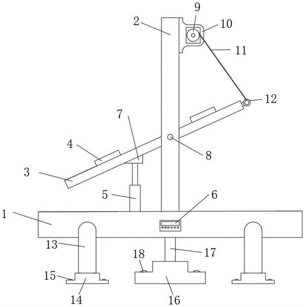
图1为本实用新型的结构示意图;Fig. 1 is the structural representation of the utility model;
图2为本实用新型的侧视图;Fig. 2 is a side view of the utility model;
图3为本实用新型太阳能板的俯视图;Fig. 3 is the top view of the utility model solar panel;
图4为本实用新型旋转底座的剖视图;Fig. 4 is a cross-sectional view of the rotating base of the utility model;
图中:1、基台;2、固定支架;3、太阳能板;4、光照传感器;5、升降杆;6、控制器;7、滑块;8、槽孔;9、滑轮;10、第一驱动电机;11、钢丝绳;12、固定环;13、固定杆;14、固定底座;15、第一螺栓;16、旋转底座;17、旋转杆;18、第二螺栓;19、连接杆;20、凹槽;21、第二驱动电机。In the figure: 1. abutment; 2. fixed bracket; 3. solar panel; 4. light sensor; 5. lifting rod; 6. controller; 7. slider; 8. slot; 9. pulley; 10. 1. drive motor; 11. wire rope; 12. fixed ring; 13. fixed rod; 14. fixed base; 15. first bolt; 16. rotating base; 17. rotating rod; 18. second bolt; 19. connecting rod; 20, the groove; 21, the second driving motor.
具体实施方式detailed description
下面将结合本实用新型实施例中的附图,对本实用新型实施例中的技术方案进行清楚、完整地描述,显然,所描述的实施例仅仅是本实用新型一部分实施例,而不是全部的实施例。基于本实用新型中的实施例,本领域普通技术人员在没有做出创造性劳动前提下所获得的所有其他实施例,都属于本实用新型保护的范围。The technical solutions in the embodiments of the present invention will be clearly and completely described below in conjunction with the accompanying drawings in the embodiments of the present invention. Obviously, the described embodiments are only part of the embodiments of the present invention, not all of them. example. Based on the embodiments of the present utility model, all other embodiments obtained by persons of ordinary skill in the art without making creative efforts belong to the scope of protection of the present utility model.
请参阅图1-图3所示,本实用新型提供如下技术方案:一种可调节角度的太阳能板,包括基台1,基台1的中间位置固定有固定支架2,固定支架2左侧设有升降杆5,升降杆5的顶端固定有滑块7,固定支架2的侧壁开设有槽孔8,相对两个槽孔8的中间位置固定有太阳能板3,太阳能板3的两侧壁固定有连接杆19,连接杆19嵌入于槽孔8中,太阳能板3的顶端固定连接有固定环12,太阳能板3的下表面中间位置开设有凹槽20,凹槽20内滑动连接有滑块7,固定支架2的侧面顶端固定有第一驱动电机10,第一驱动电机10的侧端固定连接有滑轮9,滑轮9表面连接有钢丝绳11,钢丝绳11的另一端连接在固定环12上。Please refer to Fig. 1-Fig. 3, the utility model provides the following technical solutions: a solar panel with an adjustable angle, including a
通过上述技术方案:Through the above technical solutions:
当开始调整太阳能板3的角度时,升降杆5的顶端固定有滑块7,升降杆5开始升或缩,升降杆5的顶端固定有滑块7,滑块7在太阳能板3下表面的凹槽20中滑动,太阳能板3两侧的连接杆19在槽孔8中转动,这样就可以任意调节太阳能板3的角度,太阳能板3的顶端设有固定环12,通过固定在滑轮9上的钢丝绳11连接,当第一驱动电机10接收到信号时,固定在第一驱动电机10上的滑轮9就会转动,然后通过转动来收放钢丝绳11,来达到调节太阳能板3的角度以及增加稳定性的作用。When starting to adjust the angle of the
进一步的,基台1的侧端固定连接有固定杆13,固定杆13的下端固定在固定底座14上,固定底座14通过侧端设有的第一螺栓15固定在地面上,固定杆13和固定底座14分别设有四个,且四个固定杆13和固定底座14分布在基台1的两侧,旋转底座16的下端面与固定底座14的下端面在同一水平线上。Further, the side end of the
具体地,设有四个固定杆13和固定底座14,且旋转底座16与固定底座14的下端面保持在同一水平线上,这样使整体的结构能够更加稳定。Specifically, four fixed
进一步的,太阳能板3的上表面固定有光照传感器4,光照传感器4设有两个,且两个分布在太阳能板3的上下端,基台1的侧壁中心位置固定有控制器6。Further, an
具体地,设有两个光照传感器4,目的是能够更加准确检测出当时太阳能板3的角度是否达到合理的光照角度,安装控制器6,是为了能够控制光照传感器4传出的信号。Specifically, two
请参阅图1-图2和图3所示,基台1的中心处固定有旋转杆17,旋转杆17的下端固定在旋转底座16上,旋转底座16内部底端固定有第二驱动电机21,旋转底座16通过侧端设有的第二螺栓18固定在地面上。Please refer to Fig. 1-Fig. 2 and Fig. 3, the center of the
通过上述技术方案:Through the above technical solutions:
当第二驱动电机21接收到旋转信号时,第二驱动电机21就会转动,然后带动旋转杆17旋转,旋转杆17与基台1固定连接,这样就可以带动整体旋转,包括太阳能板3,这样就可以调整太阳能板3的方向。When the
尽管已经示出和描述了本实用新型的实施例,对于本领域的普通技术人员而言,可以理解在不脱离本实用新型的原理和精神的情况下可以对这些实施例进行多种变化、修改、替换和变型,本实用新型的范围由所附权利要求及其等同物限定。Although the embodiments of the present invention have been shown and described, those skilled in the art can understand that various changes and modifications can be made to these embodiments without departing from the principle and spirit of the present invention , replacements and modifications, the scope of the present utility model is defined by the appended claims and their equivalents.
Claims (6)
Priority Applications (1)
| Application Number | Priority Date | Filing Date | Title |
|---|---|---|---|
| CN202222854510.8U CN218335888U (en) | 2022-10-28 | 2022-10-28 | But angle regulation's solar panel |
Applications Claiming Priority (1)
| Application Number | Priority Date | Filing Date | Title |
|---|---|---|---|
| CN202222854510.8U CN218335888U (en) | 2022-10-28 | 2022-10-28 | But angle regulation's solar panel |
Publications (1)
| Publication Number | Publication Date |
|---|---|
| CN218335888U true CN218335888U (en) | 2023-01-17 |
Family
ID=84826701
Family Applications (1)
| Application Number | Title | Priority Date | Filing Date |
|---|---|---|---|
| CN202222854510.8U Active CN218335888U (en) | 2022-10-28 | 2022-10-28 | But angle regulation's solar panel |
Country Status (1)
| Country | Link |
|---|---|
| CN (1) | CN218335888U (en) |
-
2022
- 2022-10-28 CN CN202222854510.8U patent/CN218335888U/en active Active
Similar Documents
| Publication | Publication Date | Title |
|---|---|---|
| CN209245947U (en) | A kind of energy-saving and environment-friendly solar energy intelligent road-lamp | |
| CN222127972U (en) | Photovoltaic power plant flexible support | |
| CN217769992U (en) | Power generation facility of adjustable photovoltaic board photic angle | |
| CN111414016A (en) | Photovoltaic power generation sun tracking device | |
| CN208794283U (en) | A kind of solar street light being easily installed with maintenance | |
| CN213027923U (en) | Photovoltaic power generation device of easy installation | |
| CN219164495U (en) | Solar panel mounting structure | |
| CN111756317A (en) | Adjustable photovoltaic cell panel assembly based on rope pulling type | |
| CN112072992A (en) | Solar photovoltaic power generation equipment for commercial illumination | |
| CN216924221U (en) | Stable solar LED street lamp with solar cell panel adjustable in angle | |
| CN215498839U (en) | Photovoltaic module with angle adjusting function for new energy power generation | |
| CN217037105U (en) | Traction type adjustable photovoltaic support with reflector | |
| CN214281288U (en) | Roof photovoltaic support | |
| CN212896803U (en) | Energy-saving green building | |
| CN208190571U (en) | A kind of intelligent solar solar panel fixing device for installing that can just rotate entirely | |
| CN211551456U (en) | A solar panel mounting structure for a solar street light | |
| CN207720074U (en) | A kind of photovoltaic bracket of solar power generation tower | |
| CN206958813U (en) | A kind of new energy road lamp energy-saving electric supply installation | |
| CN113452311B (en) | A frame assembly of a combined solar photovoltaic panel | |
| CN220775715U (en) | Photovoltaic panel installing support | |
| CN219611681U (en) | Road engineering photovoltaic power generation device | |
| CN222602323U (en) | Angle adjusting structure of solar photovoltaic module | |
| CN220541033U (en) | Photovoltaic street lamp based on perovskite photovoltaic cell | |
| CN210899022U (en) | Simple to operate's photovoltaic support | |
| CN218335823U (en) | Photovoltaic power generation board installation construction platform |
Legal Events
| Date | Code | Title | Description |
|---|---|---|---|
| GR01 | Patent grant | ||
| GR01 | Patent grant | ||
| TR01 | Transfer of patent right | ||
| TR01 | Transfer of patent right |
Effective date of registration: 20241206 Address after: No. 2-3 Chaoyang Road, Tangzhuang Town, Gaoyou City, Yangzhou City, Jiangsu Province, China 225600 Patentee after: Gaoyou Xinchen New Energy Co.,Ltd. Country or region after: China Address before: Room 1101, Building 1, Xingyuan Dingxin Science Park, No. 9, Jinxiu Middle Road, Laokeng Community, Longtian Street, Pingshan District, Shenzhen, Guangdong 518000 Patentee before: Shenzhen Yinghongda Electronics Co.,Ltd. Country or region before: China |