CN218289811U - Blank pressing device for textiles - Google Patents
Blank pressing device for textiles Download PDFInfo
- Publication number
- CN218289811U CN218289811U CN202221843220.7U CN202221843220U CN218289811U CN 218289811 U CN218289811 U CN 218289811U CN 202221843220 U CN202221843220 U CN 202221843220U CN 218289811 U CN218289811 U CN 218289811U
- Authority
- CN
- China
- Prior art keywords
- fixedly connected
- mount pad
- roller
- workstation
- piston cylinder
- Prior art date
- Legal status (The legal status is an assumption and is not a legal conclusion. Google has not performed a legal analysis and makes no representation as to the accuracy of the status listed.)
- Active
Links
- 239000004753 textile Substances 0.000 title claims description 45
- 239000004744 fabric Substances 0.000 claims abstract description 35
- 238000009434 installation Methods 0.000 claims abstract description 20
- 244000309464 bull Species 0.000 claims abstract description 5
- 239000003921 oil Substances 0.000 claims description 7
- 239000010720 hydraulic oil Substances 0.000 claims description 6
- 239000011230 binding agent Substances 0.000 claims 6
- 238000010030 laminating Methods 0.000 claims 1
- 238000004519 manufacturing process Methods 0.000 claims 1
- 230000037303 wrinkles Effects 0.000 description 7
- 230000000694 effects Effects 0.000 description 6
- 229920000728 polyester Polymers 0.000 description 2
- 230000001681 protective effect Effects 0.000 description 2
- 229920000742 Cotton Polymers 0.000 description 1
- 239000004677 Nylon Substances 0.000 description 1
- 230000004075 alteration Effects 0.000 description 1
- 230000009286 beneficial effect Effects 0.000 description 1
- 239000010727 cylinder oil Substances 0.000 description 1
- 238000010586 diagram Methods 0.000 description 1
- 230000003028 elevating effect Effects 0.000 description 1
- 238000009940 knitting Methods 0.000 description 1
- 238000000034 method Methods 0.000 description 1
- 238000012986 modification Methods 0.000 description 1
- 230000004048 modification Effects 0.000 description 1
- 229920001778 nylon Polymers 0.000 description 1
- 239000002994 raw material Substances 0.000 description 1
- 238000006467 substitution reaction Methods 0.000 description 1
- 230000001629 suppression Effects 0.000 description 1
- 238000009941 weaving Methods 0.000 description 1
- 210000002268 wool Anatomy 0.000 description 1
Images



Landscapes
- Treatment Of Fiber Materials (AREA)
Abstract
The utility model discloses a blank pressing device for fabrics belongs to fabrics processing field, a blank pressing device for fabrics, including the workstation, the first mount pad of fixed connection on the workstation rotates on the first mount pad and is connected with the pivot, fixedly connected with gear on the bull stick, first rack and second rack all with gear engagement, one side of keeping away from the installation roller on the workstation is equipped with the power unit that is used for pulling out fabrics on the installation roller. The utility model discloses a first tensioning roller and second tensioning roller are kept away from for the fabrics can obtain further tightening, and when the relative third mount pad downstream of second mount pad, the clutch blocks of being connected through extension spring and second piston rod can the downstream, and then the clutch blocks can contact with the pivot, and then the pivot rotates the resistance increase that receives, and then the fabrics is difficult to pull out from the mount roller, and then makes the tension that the fabrics received increase.
Description
Technical Field
The utility model relates to a fabrics processing technology field specifically is a blank pressing device for fabrics.
Background
Knitted fabrics include weft knitted fabrics and warp knitted fabrics according to the weaving method. The weft-knitted fabric is usually made of low-elasticity polyester yarns or special-shaped polyester yarns, nylon yarns, cotton yarns, wool yarns and the like as raw materials, flat needle tissues are adopted, flat needle tissues, rib flat needle tissues, double rib flat needle tissues, jacquard tissues, looped pile tissues and the like are changed, and the weft-knitted fabric is knitted on various weft knitting machines.
One patent with publication number CN215441068U discloses a textile fabric processing and edge pressing device, which comprises an edge pressing roller, a lifting mechanism and a driving mechanism; the two edge pressing rollers are arranged and are respectively arranged on the left side and the right side of the processing machine table; the left end and the right end of each of the two edge pressing rollers are fixedly connected with a connecting rotating shaft, one end of each connecting rotating shaft, which is far away from the edge pressing roller, is rotatably connected with a longitudinal connecting plate, and the top ends of the longitudinal connecting plates on the two connecting rotating shafts are connected with horizontal protective covers; the lifting mechanism comprises a driving cylinder arranged at the top end of the horizontal protective cover. The utility model provides a textile fabric processing blank pressing device mainly includes two blank pressing rollers, and two blank pressing rollers are installed respectively in the left and right sides of processing board, adjust its height through elevating system, control the blank pressing roller through actuating mechanism and remove about, make its strength can not realize the suppression work to the cloth avris, simultaneously, can play the effect of flattening to the surface fabric.
Although the technical scheme can achieve the effect of pressing and flattening the edge side of the cloth, the effect of controlling the flattening force of the cloth is poor, and the cloth with serious wrinkles or the cloth which cannot bear large tension is inconvenient to use.
SUMMERY OF THE UTILITY MODEL
An object of the utility model is to provide a blank pressing device for fabrics to solve the problem that proposes in the above-mentioned background art.
In order to achieve the above object, the utility model provides a following technical scheme: the utility model provides a blank pressing device for fabrics, includes the workstation, the first mount pad of fixed connection on the workstation, it is connected with the pivot to rotate on the first mount pad, fixedly connected with has the installation roller that is used for placing the fabrics in the pivot, sliding connection has second mount pad and third mount pad on the workstation, it is connected with first tensioning roller to rotate on the second mount pad, it is connected with second tensioning roller to rotate on the third mount pad, the first rack of fixedly connected with on the second mount pad, fixedly connected with second rack on the third mount pad, the lower surface rotation of workstation is connected with the bull stick, fixedly connected with gear on the bull stick, first rack and second rack all with gear engagement, one side of keeping away from the installation roller on the workstation is equipped with the power unit who is used for pulling out fabrics on the installation roller.
As a further preferred aspect of this technical scheme, a first piston cylinder is fixedly connected to the second mounting seat, a first piston rod is fixedly connected to the third mounting seat, the first piston rod is slidably connected to the first piston cylinder, a second piston cylinder is fixedly connected to the first mounting seat, a second piston rod is slidably connected to the second piston cylinder, an oil pipe is fixedly connected between the first piston cylinder and the second piston cylinder, and hydraulic oil is filled in both the first piston cylinder and the second piston cylinder.
As a further preferred of this technical scheme, sliding connection has the clutch blocks on the first mount pad, the clutch blocks is laminated with the pivot interval, fixedly connected with extension spring between clutch blocks and the second piston rod.
As a further preferred aspect of the present technical solution, the friction block is fixedly connected with a slide block, and the first mounting seat is provided with a slide groove matched with the slide block.
As a further preferred aspect of the present technical solution, a rotating disc is fixedly connected to the rotating rod.
As a further preferred of this technical scheme, power unit includes the motor, motor fixed connection is on the workstation, fixedly connected with fourth mount pad on the workstation, it is connected with first drive roller to rotate on the fourth mount pad, first drive roller fixed connection is at the output of motor, sliding connection has the rectangular block on the fourth mount pad, it is connected with the installation axle to rotate on the rectangular block, install epaxial fixedly connected with and first drive roller complex second drive roller.
As a further preferable aspect of the present technical solution, the power mechanism further includes a nut screwed on the fourth mounting seat, and the nut is rotatably connected with the rectangular block.
The utility model provides a blank pressing device for fabrics possesses following beneficial effect:
(1) The utility model discloses a detach the fold with the fabrics after first tensioning roller and second tensioning roller, then adjust the distance between first tensioning roller and the second tensioning roller to the comparatively serious fabrics of fold for first tensioning roller and second tensioning roller are kept away from, and then drive the second mount pad with gear engagement's first rack and descend, and it rises to drive the third mount pad with gear engagement's second rack, and then make the fabrics can obtain further tightening, strengthen the effect of getting rid of the fabrics fold.
(2) The utility model discloses a when the relative third mount pad downstream of second mount pad, first piston rod just can be followed and outwards taken out in the first piston cylinder, and then hydraulic oil in the second piston cylinder can enter into in the first piston cylinder through oil pipe, and then the second piston rod can slide to the second piston cylinder, when the second piston rod slides to the second piston cylinder, the clutch blocks through extension spring and second piston rod connection can the downstream, and then the clutch blocks can contact with the pivot, and then the pivot rotates the resistance increase that receives, and then the fabrics is difficult to pull out from the installation roller, and then make the tension that the fabrics received increase.
Drawings
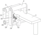
Fig. 1 is a schematic structural view of the present invention in an operating state;
FIG. 2 is a schematic view of the overall structure of the present invention;
FIG. 3 is a schematic structural view of a gear according to the present invention;
fig. 4 is a schematic structural diagram of the slide block of the present invention.
In the figure: 1. a work table; 11. a first mounting seat; 12. mounting a roller; 13. a rotating shaft; 2. a first tension roller; 21. a second mounting seat; 22. a first rack; 23. a rotating rod; 24. a gear; 25. a turntable; 3. a second tension roller; 31. a third mounting seat; 32. a second rack; 4. a motor; 41. a first driving roller; 42. a fourth mounting seat; 43. a second driving roller; 44. installing a shaft; 45. a rectangular block; 46. a nut; 5. a first piston cylinder; 51. a first piston rod; 52. an oil pipe; 53. a second piston cylinder; 54. a second piston rod; 55. a tension spring; 56. a friction block; 57. a slide block.
Detailed Description
The technical solution in the embodiments of the present invention will be clearly and completely described below with reference to the accompanying drawings in the embodiments of the present invention.
The utility model provides a technical scheme: as shown in fig. 1-3, in this embodiment, an edge pressing device for textiles includes a workbench 1, a first mounting base 11 is fixedly connected to the workbench 1, a rotating shaft 13 is rotatably connected to the first mounting base 11, a mounting roller 12 for placing textiles is fixedly connected to the rotating shaft 13, a second mounting base 21 and a third mounting base 31 are slidably connected to the workbench 1, a first tensioning roller 2 is rotatably connected to the second mounting base 21, a second tensioning roller 3 is rotatably connected to the third mounting base 31, a first rack 22 is fixedly connected to the second mounting base 21, a second rack 32 is fixedly connected to the third mounting base 31, a rotating rod 23 is rotatably connected to the lower surface of the workbench 1, a gear 24 is fixedly connected to the rotating rod 23, both the first rack 22 and the second rack 32 are engaged with the gear 24, a power mechanism for pulling out textiles on the mounting roller 12 is disposed on a side of the workbench 1 away from the mounting roller 12, the textile is wound and installed on the installation roller 12, one end of the textile is pulled out, the textile sequentially passes through the lower part of the first tensioning roller 2 and the upper part of the second tensioning roller 3 and is finally connected to the power mechanism, at the moment, the power mechanism drives the textile to be pulled out from the installation roller 12, the textile passes through the first tensioning roller 2 and the second tensioning roller 3 to remove wrinkles, the distance between the first tensioning roller 2 and the second tensioning roller 3 is adjusted for the textile with serious wrinkles, so that the first tensioning roller 2 and the second tensioning roller 3 are far away, namely, the driving gear 24 rotates anticlockwise in the state shown in the figure 3, the first rack 22 meshed with the gear 24 drives the second installation seat 21 to descend, the second rack 32 meshed with the gear 24 drives the third installation seat 31 to ascend, and further the textile can be tensioned, the removal effect on the wrinkles of the textile is enhanced.
As shown in fig. 1 and 2, a first piston cylinder 5 is fixedly connected to the second mounting seat 21, a first piston rod 51 is fixedly connected to the third mounting seat 31, the first piston rod 51 is slidably connected to the first piston cylinder 5, a second piston cylinder 53 is fixedly connected to the first mounting seat 11, a second piston rod 54 is slidably connected to the second piston cylinder 53, an oil pipe 52 is fixedly connected between the first piston cylinder 5 and the second piston cylinder 53, hydraulic oil is filled in the first piston cylinder 5 and the second piston cylinder 53, when the second mounting seat 21 moves downward relative to the third mounting seat 31, the first piston rod 51 can be drawn out from the first piston cylinder 5, and then the hydraulic oil in the second piston cylinder 53 can enter the first piston cylinder 5 through the oil pipe 52, and then the second piston rod 54 can slide into the second piston cylinder 53.
As shown in fig. 1 and 2, a friction block 56 is slidably connected to the first mounting seat 11, the friction block 56 is intermittently attached to the rotating shaft 13, a tension spring 55 is fixedly connected between the friction block 56 and the second piston rod 54, when the second piston rod 54 slides into the second piston cylinder 53, the friction block 56 connected to the second piston rod 54 through the tension spring 55 can move downward, the friction block 56 can contact the rotating shaft 13, the resistance to rotation of the rotating shaft 13 is increased, the textile is not easily torn out of the mounting roller 12, the tension applied to the textile is increased, the distance that the second mounting seat 21 slides downward relative to the third mounting seat 31 is longer, the tension applied to the friction block 56 by the second piston rod 54 is larger, and the friction between the friction block 56 and the rotating shaft 13 is larger, the tension applied to the textile is larger.
As shown in fig. 2 and 4, a sliding block 57 is fixedly connected to the friction block 56, a sliding groove matched with the sliding block 57 is formed in the first mounting seat 11, the friction block 56 can slide on the first mounting seat 11 in a limiting manner by arranging the sliding block 57, and the friction block 56 is prevented from being separated from the first mounting seat 11.
As shown in fig. 2 and 3, a rotary plate 25 is fixedly connected to the rotary rod 23, and the rotary plate 25 is arranged to allow a worker to conveniently rotate the rotary rod 23 to drive the gear 24 to rotate.
As shown in fig. 1 and 2, the power mechanism includes a motor 4, the motor 4 is fixedly connected to the workbench 1, a fourth mounting seat 42 is fixedly connected to the workbench 1, a first driving roller 41 is rotatably connected to the fourth mounting seat 42, the first driving roller 41 is fixedly connected to an output end of the motor 4, a rectangular block 45 is slidably connected to the fourth mounting seat 42, a mounting shaft 44 is rotatably connected to the rectangular block 45, a second driving roller 43 matched with the first driving roller 41 is fixedly connected to the mounting shaft 44, the textile is passed between the first driving roller 41 and the second driving roller 43, the motor 4 is started to rotate the first driving roller 41, and the textile is pulled out from the mounting roller 12 by friction force between the textile and the second driving roller 43 when the first driving roller 41 rotates.
As shown in fig. 1 and 2, the power mechanism further includes a nut 46 screwed on the fourth mounting seat 42, the nut 46 is rotatably connected with the rectangular block 45, the rectangular block 45 can be controlled to move up and down in the fourth mounting seat 42 by rotating the nut 46, and further, the distance between the first driving roller 41 and the second driving roller 43 can be adjusted, so as to adapt to textiles with different thicknesses.
The utility model provides a blank pressing device for fabrics, concrete theory of operation as follows:
the textile is wound and installed on the installation roller 12, one end of the textile is pulled out, the textile sequentially penetrates through the lower portion of the first tensioning roller 2 and the upper portion of the second tensioning roller 3 and is finally connected to the power mechanism, at the moment, the power mechanism drives the textile to be pulled out from the installation roller 12, the textile is removed from wrinkles after passing through the first tensioning roller 2 and the second tensioning roller 3, the distance between the first tensioning roller 2 and the second tensioning roller 3 is adjusted for the textile with serious wrinkles, the first tensioning roller 2 and the second tensioning roller 3 are kept away, namely, the driving gear 24 rotates anticlockwise in the state of figure 3, the first rack 22 meshed with the gear 24 drives the second installation seat 21 to descend, the second rack 32 meshed with the gear 24 drives the third installation seat 31 to ascend, the textile can be further tightened, and the removal effect of the wrinkles on the textile is enhanced;
when the second mounting seat 21 moves downward relative to the third mounting seat 31, the first piston rod 51 can be drawn out from the first piston cylinder 5, and then hydraulic oil in the second piston cylinder 53 can enter the first piston cylinder 5 through the oil pipe 52, and then the second piston rod 54 can slide in the second piston cylinder 53, when the second piston rod 54 slides in the second piston cylinder 53, the friction block 56 connected with the second piston rod 54 through the tension spring 55 can move downward, and then the friction block 56 can be contacted with the rotating shaft 13, so that the resistance received by the rotating shaft 13 is increased, and further the textile is not easy to be pulled out from the mounting roller 12, so that the tension received by the textile is increased, the larger the downward sliding distance of the second mounting seat 21 relative to the third mounting seat 31 is, the longer the downward sliding distance of the second piston rod 54 is, and further the larger the tension applied to the friction block 56 by the second piston rod 54 through the tension spring 55 is, and the larger the friction force between the friction block 56 and the rotating shaft 13 is, the larger the tension received by the textile is;
the textile passes through the space between the first driving roller 41 and the second driving roller 43, the first driving roller 41 is rotated by the starting motor 4, the textile is pulled out of the mounting roller 12 under the action of friction force between the textile and the second driving roller 43 when the first driving roller 41 rotates, the rectangular block 45 can be controlled to move up and down in the fourth mounting seat 42 through the rotating nut 46, and then the distance between the first driving roller 41 and the second driving roller 43 can be adjusted, so that the textile with different thicknesses can be adapted.
Although embodiments of the present invention have been shown and described, it will be appreciated by those skilled in the art that changes, modifications, substitutions and alterations can be made in these embodiments without departing from the principles and spirit of the invention, the scope of which is defined in the appended claims and their equivalents.
Claims (7)
1. The utility model provides a blank pressing device for fabrics, includes workstation (1), its characterized in that: the utility model discloses a textile manufacturing machine, including workstation (1), workstation (1) go up the first mount pad of fixed connection (11), it is connected with pivot (13) to rotate on first mount pad (11), fixedly connected with has installation roller (12) that are used for placing the textile on pivot (13), sliding connection has second mount pad (21) and third mount pad (31) on workstation (1), it is connected with first tensioning roller (2) to rotate on second mount pad (21), it is connected with second tensioning roller (3) to rotate on third mount pad (31), the first rack of fixedly connected with (22) on second mount pad (21), fixedly connected with second rack (32) on third mount pad (31), the lower surface rotation of workstation (1) is connected with bull stick (23), fixedly connected with gear (24) on bull stick (23), first rack (22) and second rack (32) all mesh with gear (24), one side of keeping away from installation roller (12) on workstation (1) is equipped with the power unit that is used for pulling out installation roller (12).
2. A binder assembly for a textile article according to claim 1 including: the hydraulic cylinder is characterized in that a first piston cylinder (5) is fixedly connected to the second mounting seat (21), a first piston rod (51) is fixedly connected to the third mounting seat (31), the first piston rod (51) is connected to the first piston cylinder (5) in a sliding mode, a second piston cylinder (53) is fixedly connected to the first mounting seat (11), a second piston rod (54) is connected to the second piston cylinder (53) in the sliding mode, an oil pipe (52) is fixedly connected between the first piston cylinder (5) and the second piston cylinder (53), and hydraulic oil is filled in the first piston cylinder (5) and the second piston cylinder (53).
3. A binder assembly for a textile article according to claim 2 wherein: sliding connection has clutch blocks (56) on first mount pad (11), clutch blocks (56) and pivot (13) intermittent type laminating, fixedly connected with extension spring (55) between clutch blocks (56) and second piston rod (54).
4. A binder assembly for a textile article according to claim 3 wherein: the friction block (56) is fixedly connected with a sliding block (57), and the first mounting seat (11) is provided with a sliding groove matched with the sliding block (57).
5. A binder assembly for a textile article in accordance with claim 1, wherein: and a turntable (25) is fixedly connected to the rotating rod (23).
6. A binder assembly for a textile article in accordance with claim 1, wherein: power unit includes motor (4), motor (4) fixed connection is on workstation (1), fixedly connected with fourth mount pad (42) is gone up in workstation (1), it is connected with first drive roller (41) to rotate on fourth mount pad (42), first drive roller (41) fixed connection is at the output of motor (4), sliding connection has rectangular block (45) on fourth mount pad (42), rotating connection has installation axle (44) on rectangular block (45), fixedly connected with and first drive roller (41) complex second drive roller (43) are gone up in installation axle (44).
7. A binder assembly for a textile article according to claim 6 further comprising: the power mechanism further comprises a nut (46) in threaded connection with the fourth mounting seat (42), and the nut (46) is rotatably connected with the rectangular block (45).
Priority Applications (1)
| Application Number | Priority Date | Filing Date | Title |
|---|---|---|---|
| CN202221843220.7U CN218289811U (en) | 2022-07-18 | 2022-07-18 | Blank pressing device for textiles |
Applications Claiming Priority (1)
| Application Number | Priority Date | Filing Date | Title |
|---|---|---|---|
| CN202221843220.7U CN218289811U (en) | 2022-07-18 | 2022-07-18 | Blank pressing device for textiles |
Publications (1)
| Publication Number | Publication Date |
|---|---|
| CN218289811U true CN218289811U (en) | 2023-01-13 |
Family
ID=84789001
Family Applications (1)
| Application Number | Title | Priority Date | Filing Date |
|---|---|---|---|
| CN202221843220.7U Active CN218289811U (en) | 2022-07-18 | 2022-07-18 | Blank pressing device for textiles |
Country Status (1)
| Country | Link |
|---|---|
| CN (1) | CN218289811U (en) |
Cited By (2)
| Publication number | Priority date | Publication date | Assignee | Title |
|---|---|---|---|---|
| CN117758401A (en) * | 2023-12-26 | 2024-03-26 | 安徽翰联色纺股份有限公司 | Air-jet spinning device with spinning starter system and method thereof |
| CN119370668A (en) * | 2025-01-01 | 2025-01-28 | 内蒙古普泽新材料科技有限公司 | A swing felting and weighing pressurizing system for mineral wool |
-
2022
- 2022-07-18 CN CN202221843220.7U patent/CN218289811U/en active Active
Cited By (3)
| Publication number | Priority date | Publication date | Assignee | Title |
|---|---|---|---|---|
| CN117758401A (en) * | 2023-12-26 | 2024-03-26 | 安徽翰联色纺股份有限公司 | Air-jet spinning device with spinning starter system and method thereof |
| CN119370668A (en) * | 2025-01-01 | 2025-01-28 | 内蒙古普泽新材料科技有限公司 | A swing felting and weighing pressurizing system for mineral wool |
| CN119370668B (en) * | 2025-01-01 | 2025-03-18 | 内蒙古普泽新材料科技有限公司 | Swing felt laying and weighing pressurizing system for mineral cotton |
Similar Documents
| Publication | Publication Date | Title |
|---|---|---|
| CN114474958B (en) | Forming process and forming device of carbon fiber preform | |
| CN114438768B (en) | High-stability cutting device for textile processing and using method thereof | |
| CN212865312U (en) | Ironing device for textile fabric | |
| CN116374732A (en) | A textile thread winding mechanism | |
| CN118850839B (en) | Winding device for textile fabric processing | |
| CN201857476U (en) | Plastic cylinder braiding machine | |
| CN112342773A (en) | Cutting device for textile fabric | |
| CN216193195U (en) | Cloth dragging wheel device of sewing equipment | |
| CN218880351U (en) | Flattening mechanism | |
| CN219519436U (en) | Tensioning equipment for PE coating of box wrapping cloth | |
| CN218711248U (en) | Jacquard flat machine | |
| CN201924140U (en) | Jacquard cloth pressing mechanism of plastic cylinder knitting machine | |
| CN220538108U (en) | Cotton quilt edge covering device | |
| CN211771900U (en) | Cotton quilt edge covering traction device | |
| CN222935633U (en) | Double roller combination structure of a flat knitting machine | |
| CN113668145B (en) | A mopping wheel device for sewing equipment | |
| CN223226324U (en) | Antibacterial layer dip dyeing device for antibacterial fabric | |
| CN214005234U (en) | Shearing device is used in textile fabric production | |
| CN209740343U (en) | Winding device for textile fabric processing | |
| CN86201045U (en) | Fabric collator | |
| CN115367531A (en) | Non-woven fabrics processing is with preventing fold device | |
| CN208023193U (en) | A kind of braider | |
| CN213261562U (en) | Lifting device for hot roll of compound machine | |
| CN223281053U (en) | Knitted fabric straightening device | |
| CN219791895U (en) | Textile fabric conveying mechanism |
Legal Events
| Date | Code | Title | Description |
|---|---|---|---|
| GR01 | Patent grant | ||
| GR01 | Patent grant |