CN218273232U - A touchable smart notebook computer - Google Patents
A touchable smart notebook computer Download PDFInfo
- Publication number
- CN218273232U CN218273232U CN202222599932.5U CN202222599932U CN218273232U CN 218273232 U CN218273232 U CN 218273232U CN 202222599932 U CN202222599932 U CN 202222599932U CN 218273232 U CN218273232 U CN 218273232U
- Authority
- CN
- China
- Prior art keywords
- base
- fixedly connected
- notebook computer
- touchable
- groove
- Prior art date
- Legal status (The legal status is an assumption and is not a legal conclusion. Google has not performed a legal analysis and makes no representation as to the accuracy of the status listed.)
- Active
Links
Images

Landscapes
- Casings For Electric Apparatus (AREA)
Abstract
Description
技术领域technical field
本实用新型涉及笔记本电脑技术领域,尤其涉及一种可触控智能笔记本电脑。The utility model relates to the technical field of notebook computers, in particular to a touchable intelligent notebook computer.
背景技术Background technique
可触控智能笔记本电脑是一种电脑的一种,电脑通常分为台式电脑、一体机电脑和笔记本电脑,可触控笔记本电脑的显示屏采用的是触摸显示屏,能够方便使用者通过显示屏触控操作笔记本电脑。Touchable smart notebook computer is a kind of computer. Computers are usually divided into desktop computers, all-in-one computers and notebook computers. Touch operated laptop.
现有的可触控智能笔记本电脑在使用过程中,显示屏容易受到挤压,从而导致屏幕受损,影响触控效果;且利用橡胶块进行保护起到的作用有限,因此需要一种可触控智能笔记本电脑。During the use of existing touchable smart notebook computers, the display screen is easily squeezed, resulting in damage to the screen and affecting the touch effect; and the use of rubber blocks for protection has limited effect, so a touchable control smart laptops.
实用新型内容Utility model content
本实用新型的目的是为了解决现有技术中存在的缺点,而提出的一种可触控智能笔记本电脑。The purpose of the utility model is to solve the shortcomings in the prior art, and propose a touchable smart notebook computer.
为了实现上述目的,本实用新型采用了如下技术方案:In order to achieve the above object, the utility model adopts the following technical solutions:
一种可触控智能笔记本电脑,包括底座1,所述底座1的内部固定连接有连接轴2,所述连接轴2的内部转动连接有安装板3,所述安装板3的内部开设有第一安装槽4,所述第一安装槽4的内侧壁设置有滑槽5,所述滑槽5的内侧壁滑动连接有滑块6,所述滑块6的侧表面固定连接有弹簧7,所述弹簧7远离所述滑块6的一端与所述第一安装槽4的内底部固定连接;所述底座1的外表面固定连接有限位块8,所述限位块8的位置与所述滑块6的位置相对应;所述底座1的外表面固定连接有两个橡胶块9,两个所述橡胶块9对称分布;所述安装板3的内部安装有显示屏10。A touchable smart notebook computer, comprising a
可选地,所述底座1的外表面安装有触摸板11。Optionally, a
可选地,所述底座1的底部开设有散热口13,所述散热口13的两侧均设置有限位槽14。Optionally, the bottom of the
可选地,所述限位槽14的内侧壁转动连接有连接杆15,所述连接杆15远离所述限位槽14的一端活动连接有支撑块16。Optionally, a connecting
可选地,所述底座1的底部开设有第二安装槽17;所述第二安装槽17的内部滑动连接有限位板19,所述限位板19远离所述第二安装槽17的一端位于所述限位槽14的内部。Optionally, the bottom of the
可选地,所述底座1的底部开设有矩形槽;所述矩形槽的内侧壁滑动连接有连接块18,所述连接块18远离所述矩形槽的一端与所述限位板19的外表面固定连接。Optionally, a rectangular slot is opened on the bottom of the
可选地,所述底座1的底部固定连接有4个防滑垫12。Optionally, four
本实用新型具有如下有益效果:The utility model has the following beneficial effects:
1、本实用新型的可触控智能笔记本电脑,由于设置了滑块、弹簧和限位块,当安装板带动显示屏向下移动时,限位块会对滑块产生压力,滑块利用弹簧进行缓冲,有利于增强装置的保护性,延长显示屏的使用寿命,避免显示屏受到挤压导致损坏。1. The touchable smart notebook computer of the present invention is equipped with a slider, a spring and a limit block. When the installation plate drives the display screen to move downward, the limit block will exert pressure on the slider, and the slider uses the spring to move downward. Buffering is beneficial to enhance the protection of the device, prolong the service life of the display screen, and prevent the display screen from being damaged due to extrusion.
2、本实用新型的可触控智能笔记本电脑,由于设置了连接杆和支撑块,限位板可对支撑块进行限位,在使用时推动连接块可将支撑块与连接杆取出;且支撑块可以对连接杆进行支撑,有利于提升装置的散热效果,避免装置底部通风不畅影响散热。2. For the touchable smart notebook computer of the present invention, since the connecting rod and the supporting block are provided, the limiting plate can limit the supporting block, and the supporting block and the connecting rod can be taken out by pushing the connecting block during use; and the supporting The block can support the connecting rod, which is beneficial to improve the heat dissipation effect of the device, and avoid the poor ventilation at the bottom of the device from affecting heat dissipation.
附图说明Description of drawings
为了更清楚地说明本实用新型实施例或现有技术中的技术方案,下面将对实施例中所需要使用的附图作简单地介绍,显而易见地,下面描述中的附图仅仅是本实用新型的一些实施例,对于本领域普通技术人员来讲,在不付出创造性劳动性的前提下,还可以根据这些附图获得其他的附图。In order to more clearly illustrate the technical solutions in the embodiments of the present invention or the prior art, the accompanying drawings required in the embodiments will be briefly introduced below. Obviously, the accompanying drawings in the following description are only the present invention For some embodiments of the present invention, those skilled in the art can also obtain other drawings based on these drawings without paying creative efforts.
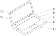
图1为本实施例公开的可触控智能笔记本电脑的整体结构示意图;FIG. 1 is a schematic diagram of the overall structure of the touchable smart notebook computer disclosed in this embodiment;
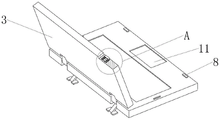
图2为本实施例公开的可触控智能笔记本电脑的剖视图;Fig. 2 is a sectional view of the touchable smart notebook computer disclosed in this embodiment;
图3为本实施例公开的图2中A处放大图;Fig. 3 is an enlarged view of A in Fig. 2 disclosed in this embodiment;
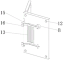
图4为本实施例公开的可触控智能笔记本电脑的底部结构示意图;FIG. 4 is a schematic diagram of the bottom structure of the touchable smart notebook computer disclosed in this embodiment;
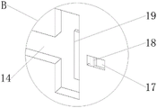
图5为本实施例公开的图4中B处放大图。Fig. 5 is an enlarged view of B in Fig. 4 disclosed in this embodiment.
图例说明:illustration:
1、底座;2、连接轴;3、安装板;4、第一安装槽;5、滑槽;6、滑块;7、弹簧;8、限位块;9、橡胶块;10、显示屏;11、触摸板;12、防滑垫;13、散热口;14、限位槽;15、连接杆;16、支撑块;17、第二安装槽;18、连接块;19、限位板。1. Base; 2. Connecting shaft; 3. Mounting plate; 4. First installation groove; 5. Chute; 6. Slider; 7. Spring; 8. Limiting block; 9. Rubber block; 10. Display ; 11, touch panel; 12, anti-skid pad; 13, heat dissipation port; 14, limit groove; 15, connecting rod; 16, support block; 17, second installation groove;
具体实施方式detailed description
下面将结合本实用新型实施例中的附图,对本实用新型实施例中的技术方案进行清楚、完整地描述,显然,所描述的实施例仅仅是本实用新型一部分实施例,而不是全部的实施例。基于本实用新型中的实施例,本领域普通技术人员在没有做出创造性劳动前提下所获得的所有其他实施例,都属于本实用新型保护的范围。The technical solutions in the embodiments of the present invention will be clearly and completely described below in conjunction with the accompanying drawings in the embodiments of the present invention. Obviously, the described embodiments are only part of the embodiments of the present invention, not all of them. example. Based on the embodiments of the present utility model, all other embodiments obtained by persons of ordinary skill in the art without making creative efforts belong to the scope of protection of the present utility model.
本实用新型的说明书和权利要求书以及上述附图中的术语“第一”、“第二”、“第三”等(如果存在)是用于区别类似的对象,而不必用于描述特定的顺序或先后次序。应当理解,这样描述的对象在适当情况下可以互换。此外,术语“包括”和“具有”以及他们的任何变形,意图在于覆盖不排他的包含。The terms "first", "second", "third", etc. (if any) in the description and claims of the present utility model and the above drawings are used to distinguish similar objects and not necessarily to describe specific sequence or sequence. It should be understood that the objects so described are interchangeable under appropriate circumstances. Furthermore, the terms "comprising" and "having", as well as any variations thereof, are intended to cover a non-exclusive inclusion.
在本实用新型中,下文论述的附图以及用来描述本实用新型公开的原理的各实施例仅用于说明,而不应解释为限制本实用新型公开的范围。所属领域的技术人员将理解,本实用新型的原理可在任何适当布置的系统中实施。将详细说明示例性实施方式,在附图中示出了这些实施方式的实例。此外,将参考附图详细描述根据示例性实施例的终端。附图中的相同附图标号指代相同的元件。In the present utility model, the drawings discussed below and the various embodiments used to describe the principles disclosed in the utility model are only for illustration, and should not be construed as limiting the scope of the utility model disclosure. Those skilled in the art will understand that the principles of the invention may be implemented in any suitably arranged system. Reference will now be made in detail to exemplary embodiments, examples of which are illustrated in the accompanying drawings. Also, a terminal according to an exemplary embodiment will be described in detail with reference to the accompanying drawings. The same reference numerals in the figures refer to the same elements.
本实用新型说明书中使用的术语仅用来描述特定实施方式,而并不意图显示本实用新型的概念。除非上下文中有明确不同的意义,否则,以单数形式使用的表达涵盖复数形式的表达。在本实用新型说明书中,应理解,诸如“包括”、“具有”以及“含有”等术语意图说明存在本实用新型说明书中揭示的特征、数字、步骤、动作或其组合的可能性,而并不意图排除可存在或可添加一个或多个其他特征、数字、步骤、动作或其组合的可能性。附图中的相同参考标号指代相同部分。Terms used in the description of the present invention are only used to describe specific embodiments, and are not intended to show the concept of the present invention. Expressions used in the singular encompass expressions in the plural unless there is a clearly different meaning in the context. In the specification of the utility model, it should be understood that terms such as "comprising", "having" and "containing" are intended to indicate the possibility of the features, numbers, steps, actions or combinations thereof disclosed in the specification of the utility model, and not It is not intended to exclude the possibility that one or more other features, numbers, steps, actions or combinations thereof may be present or may be added. The same reference numerals in the drawings refer to the same parts.
本实用新型的目的是为了解决现有技术中存在的缺点,而提出的一种可触控智能笔记本电脑。The purpose of the utility model is to solve the shortcomings in the prior art, and propose a touchable smart notebook computer.
为使本实用新型的上述目的、特征和优点能够更加明显易懂,下面结合附图和具体实施方式对本实用新型作进一步详细的说明。In order to make the above purpose, features and advantages of the utility model more obvious and understandable, the utility model will be further described in detail below in conjunction with the accompanying drawings and specific embodiments.
参照图1-5,本实施例公开的一种可触控智能笔记本电脑,包括底座1,底座1的内部固定连接有连接轴2,连接轴2的内部转动连接有安装板3,连接轴2便于安装板3带动显示屏10进行转动,从而对角度进行调节。安装板3的内部开设有第一安装槽4,第一安装槽4的内侧壁设置有滑槽5,滑槽5的内侧壁滑动连接有滑块6,滑块6的侧表面固定连接有弹簧7,且弹簧7远离滑块6的一端与第一安装槽4的内底部固定连接。底座1的外表面固定连接有限位块8,限位块8与滑块6的位置相对应。底座1的外表面固定连接有橡胶块9,橡胶块9的数量为两个,且呈对称分布。安装板3的内部安装有显示屏10。滑块6在滑槽5的内部进行移动,从而对弹簧7进行挤压,便于通过弹簧7对滑块6的受力进行缓冲,有利于保护显示屏10,使其避免受到挤压。Referring to Figures 1-5, a touchable smart notebook computer disclosed in this embodiment includes a
在本实施例中,底座1的外表面安装有触摸板11,触摸板11位于两个限位块8之间。触摸板11用于进行电脑操作。In this embodiment, a
在本实施例中,底座1的底部开设有散热口13,散热口13的两侧均设置有限位槽14。散热口13配合连接杆15和支撑块16将底座1进行抬升,有利于增强装置的散热效果。In this embodiment, the bottom of the
在本实施例中,限位槽14的内侧壁转动连接有连接杆15,连接杆15远离限位槽14的一端活动连接有支撑块16。In this embodiment, the inner sidewall of the limiting
进一步地,底座1的底部开设有第二安装槽17,第二安装槽17的内部滑动连接有限位板19,限位板19远离第二安装槽17的一端位于限位槽14的内部。第二安装槽17便于利用连接块18对限位板19进行推动,使其对支撑块16进行限位,第二安装槽17的内部设置有小弹簧,可对限位板19进行推动。Further, the bottom of the
进一步地,底座1的底部开设有矩形槽,矩形槽的内侧壁滑动连接有连接块18,连接块18远离矩形槽的一端与限位板19的外表面固定连接。Further, the bottom of the
进一步地,底座1的底部固定连接有防滑垫12,防滑垫12的数量为4个,呈对称分布。Further, the bottom of the
工作原理:working principle:
当合上安装板3时,限位块8会对滑块6进行接触,滑块6通过弹簧7对外部受力进行缓冲,有利于保护显示屏10,避免显示屏10受到挤压导致损坏;同时两侧橡胶块9对安装板3进行限位,避免安装板3与底座1的外表面直接贴合,再将连接杆15与支撑块16移出进行支撑,便于增强装置的散热效果。When the mounting
本说明书中各个实施例采用递进的方式描述,每个实施例重点说明的都是与其他实施例的不同之处,各个实施例之间相同相似部分互相参见即可。Each embodiment in this specification is described in a progressive manner, each embodiment focuses on the difference from other embodiments, and the same and similar parts of each embodiment can be referred to each other.
本文中应用了具体个例对本实用新型的原理及实施方式进行了阐述,以上实施例的说明只是用于帮助理解本实用新型的核心思想;同时,对于本领域的一般技术人员,依据本实用新型的思想,在具体实施方式及应用范围上均会有改变之处。综上所述,本说明书内容不应理解为对本实用新型的限制。In this paper, specific examples are used to illustrate the principle and implementation of the present utility model. The description of the above embodiments is only used to help understand the core idea of the present utility model; meanwhile, for those skilled in the art, according to the utility model Thoughts, there will be changes in specific implementation methods and application ranges. To sum up, the contents of this specification should not be understood as limiting the utility model.
Claims (7)
Priority Applications (1)
| Application Number | Priority Date | Filing Date | Title |
|---|---|---|---|
| CN202222599932.5U CN218273232U (en) | 2022-09-29 | 2022-09-29 | A touchable smart notebook computer |
Applications Claiming Priority (1)
| Application Number | Priority Date | Filing Date | Title |
|---|---|---|---|
| CN202222599932.5U CN218273232U (en) | 2022-09-29 | 2022-09-29 | A touchable smart notebook computer |
Publications (1)
| Publication Number | Publication Date |
|---|---|
| CN218273232U true CN218273232U (en) | 2023-01-10 |
Family
ID=84747911
Family Applications (1)
| Application Number | Title | Priority Date | Filing Date |
|---|---|---|---|
| CN202222599932.5U Active CN218273232U (en) | 2022-09-29 | 2022-09-29 | A touchable smart notebook computer |
Country Status (1)
| Country | Link |
|---|---|
| CN (1) | CN218273232U (en) |
-
2022
- 2022-09-29 CN CN202222599932.5U patent/CN218273232U/en active Active
Similar Documents
| Publication | Publication Date | Title |
|---|---|---|
| US11914432B2 (en) | Portable electronic device | |
| CN211928498U (en) | Hard disk mounting structure for computer | |
| CN219588482U (en) | An Improved Large Screen Display System | |
| CN207817583U (en) | Industrial control all-in-one machine | |
| CN108776507A (en) | A kind of flush type mounting structure of notebook Trackpad | |
| CN220605021U (en) | USB interface and docking station | |
| CN210954829U (en) | Double-video expander of notebook computer | |
| CN207625026U (en) | A HDMI socket assembly | |
| CN211928497U (en) | An efficient fixing device for computer hardware | |
| CN202735914U (en) | Electronic device with turnover limiting function | |
| CN217982260U (en) | All-in-one computer with socket protection mechanism | |
| CN209373515U (en) | A kind of computer hard disc mounting structure | |
| CN219476049U (en) | docking station for laptop | |
| CN218413392U (en) | Work station | |
| CN211149338U (en) | Novel external plug-in OCP network card fixing device | |
| CN206195803U (en) | Novel connection of miniaturized power supply and signal sharing device | |
| CN114188770B (en) | A VGA electrical connector with protective structure | |
| CN205485754U (en) | Structure of intelligent computer mainboard | |
| CN221765979U (en) | A server with a supporting installation structure | |
| CN217903548U (en) | Dustproof slot structure of computer hardware | |
| CN209389379U (en) | An external computer USB interface expansion device | |
| CN217902345U (en) | A laptop computer that is convenient for covering the camera | |
| CN218975336U (en) | Combined isolating switch | |
| CN217932540U (en) | Data miner for big data analysis | |
| CN218158941U (en) | A computer case with expandable ups module |
Legal Events
| Date | Code | Title | Description |
|---|---|---|---|
| GR01 | Patent grant | ||
| GR01 | Patent grant | ||
| PP01 | Preservation of patent right |
Effective date of registration: 20250813 Granted publication date: 20230110 |
|
| PP01 | Preservation of patent right |