CN218261744U - Prestressed tensioning jack lifting device - Google Patents
Prestressed tensioning jack lifting device Download PDFInfo
- Publication number
- CN218261744U CN218261744U CN202221641364.4U CN202221641364U CN218261744U CN 218261744 U CN218261744 U CN 218261744U CN 202221641364 U CN202221641364 U CN 202221641364U CN 218261744 U CN218261744 U CN 218261744U
- Authority
- CN
- China
- Prior art keywords
- fixed mounting
- threaded rod
- bispin
- supporting
- support post
- Prior art date
- Legal status (The legal status is an assumption and is not a legal conclusion. Google has not performed a legal analysis and makes no representation as to the accuracy of the status listed.)
- Active
Links
- 238000000034 method Methods 0.000 description 13
- 230000008569 process Effects 0.000 description 6
- 230000009471 action Effects 0.000 description 4
- 230000001174 ascending effect Effects 0.000 description 2
- 230000008901 benefit Effects 0.000 description 2
- 238000010276 construction Methods 0.000 description 2
- 230000007246 mechanism Effects 0.000 description 2
- 230000010363 phase shift Effects 0.000 description 2
- 229910000831 Steel Inorganic materials 0.000 description 1
- 230000004075 alteration Effects 0.000 description 1
- 230000009286 beneficial effect Effects 0.000 description 1
- 230000005540 biological transmission Effects 0.000 description 1
- 238000010586 diagram Methods 0.000 description 1
- 230000004048 modification Effects 0.000 description 1
- 238000012986 modification Methods 0.000 description 1
- 239000010959 steel Substances 0.000 description 1
- 238000006467 substitution reaction Methods 0.000 description 1
Images



Landscapes
- Invalid Beds And Related Equipment (AREA)
Abstract
The utility model relates to a prestressing force stretch-draw jack hoisting device, including the supporting baseplate, the last surface right side fixed mounting of supporting baseplate has two fixing bases, two movable mounting has bispin to the threaded rod between the fixing base, the equal threaded connection in the left and right sides of bispin to the threaded rod has lateral shifting block, two the equal fixed mounting in upper surface of lateral shifting block has lower connecting seat, the bispin is equipped with the support post to the intermediate position outside of threaded rod, the inside swing joint of support post has vertical lift post, the equal fixed mounting in the left and right sides of vertical lift post has last connecting seat, the top of support post is equipped with the jack body. This prestressing force stretch-draw jack hoisting device has realized the longitudinal movement of jack body through setting up bispin to threaded rod, lateral shifting piece, vertical lifting column and support member, is provided with removal wheel and lip block simultaneously, has guaranteed the overall stability of device.
Description
Technical Field
The utility model relates to a prestressing force stretch-draw jack technical field specifically is a prestressing force stretch-draw jack hoisting device.
Background
The prestressed jack is a special jack for tensioning prestressed bars such as steel strand wires. The prestress jack is a straight-through hydraulic double-acting jack and needs to be matched with a high-pressure oil pump for use, and the power for tensioning and jacking is provided by high-pressure oil of the high-pressure oil pump. The jack can be divided into a front clamping jack and a common feed-through jack according to different structures. The prestressed jack has compact structure, stable work during tensioning, high oil pressure and large tension force, and is widely applied to prestressed construction projects such as highway bridges, railway bridges, hydroelectric dam bodies, high-rise buildings and the like.
The prestressed jack has the advantages of large volume, heavy weight, difficult transportation, complex positioning process, no special height adjusting mechanism, large manpower consumption for realizing the lifting work of the prestressed jack, serious restriction on the construction period and increase of the labor cost. The present invention was made in view of the above problems.
SUMMERY OF THE UTILITY MODEL
To prior art's not enough, the utility model provides a prestressing force tensioning jack hoisting device possesses and can carry out the ascending removal of vertical side fast, stability advantage such as higher, has solved current prestressing force jack that mentions in the above-mentioned background art and has not dedicated height adjustment mechanism, need consume the problem that the promotion work of a large amount of manpowers could realize prestressing force jack.
In order to achieve the above purpose, the utility model provides a following technical scheme: the utility model provides a prestressing force tensioning jack hoisting device, includes supporting baseplate, supporting baseplate's upper surface right side fixed mounting has two fixing bases, two movable mounting has the bispin to the threaded rod between the fixing base, the equal threaded connection in the left and right sides of bispin to the threaded rod has the lateral shifting piece, two the equal fixed mounting in upper surface of lateral shifting piece has lower connecting seat, the intermediate position outside of bispin to the threaded rod is equipped with the support post, support post fixed mounting is at the upper surface of supporting baseplate, the support post has all seted up the logical groove of longitudinal connection for the left and right sides face of hollow structure and support post, the inside swing joint of support post has the longitudinal lift post, the equal fixed mounting in the left and right sides of longitudinal lift post has last connecting seat, is located leftwards go up between connecting seat and the lower connecting seat and lie in the right side between last connecting seat and the lower connecting seat equal movable mounting have the support member, the top of support post is equipped with the jack body.
Further, first belt pulley has been cup jointed to the right-hand member of bispin to the threaded rod, supporting baseplate's upper surface right side fixed mounting has L shape motor mounting panel, the rear side at the bispin to the threaded rod is established to L shape motor mounting panel, fixed mounting has driving motor on the L shape motor mounting panel, and driving motor stability when the operation has been guaranteed to L shape motor mounting panel, driving motor's output has been cup jointed the second belt pulley, be equipped with driving belt between second belt pulley and the first belt pulley.
Further, two smooth slide bars are fixedly mounted between the two fixing seats, the two smooth slide bars are respectively arranged on the front side and the rear side of the double-spiral-direction threaded rod, limiting blocks are fixedly connected to the front side and the rear side of the two transverse moving blocks, limiting holes are transversely formed in the limiting blocks, and the smooth slide bars and the limiting holes limit the transverse moving blocks.
Further, two be equipped with the supporting seat between the fixing base, supporting seat fixed mounting is at the upper surface of supporting baseplate, the bispin is to the threaded rod and passes the supporting seat, and the stability of bispin to the threaded rod in the rotation process has been guaranteed to the supporting seat.
Furthermore, the inside intermediate position fixed mounting of support post has the guide post, the connecting hole has been seted up to the intermediate position of vertical lift post, the diameter of guide post is the same with the diameter of connecting hole, the size of vertical lift post is the same with the inside size of support post, has realized spacing to vertical lift post.
Furthermore, the top fixed mounting of vertical promotion post has the connecting frame, the jack body is established in the connecting frame, and the connecting frame has guaranteed the stability of jack body at the longitudinal movement in-process.
Further, the equal fixed mounting of lower surface four corners department of supporting baseplate has the removal wheel, is convenient for realize the utility model discloses a remove.
Further, the equal fixed mounting in intermediate position of both sides face has a connecting block, two around the supporting baseplate the intermediate position of connecting block all sets up threaded hole, two equal threaded connection has the screw rod spare in the connecting block, the top fixed mounting of screw rod spare has rotatory rocking handle, the bottom fixed mounting of screw rod spare has the lip block, and the lip block has guaranteed the utility model discloses stability when using.
Compared with the prior art, the technical scheme of the application has the following beneficial effects:
1. according to the prestress tensioning jack lifting device, the driving motor is started when the prestress tensioning jack lifting device is used by arranging the double-turning threaded rod, the transverse moving blocks, the longitudinal lifting column and the supporting rod piece, the double-turning threaded rod is rotated under the connection of the first belt pulley, the second belt pulley and the transmission belt, the two transverse moving blocks move oppositely or oppositely in the rotating process of the double-turning threaded rod, and the jack body is longitudinally moved under the action of the lower connecting seat, the supporting rod piece and the upper connecting seat, so that the principle is simple, and the prestress tensioning jack lifting device is easy to install and maintain;
2. this prestressing force stretch-draw jack hoisting device removes the wheel through setting up, has improved the utility model discloses flexibility when using, through setting up screw rod spare, rotatory rocking handle and lip block, rotate rotatory rocking handle when using, rotatory rocking handle drives screw rod spare and lip block and moves down to guaranteed the utility model discloses stability in the use.
Drawings
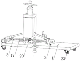
Fig. 1 is a schematic view of the overall structure of the present invention;
fig. 2 is a rear view of the present invention;
fig. 3 is a side view of the present invention;
fig. 4 is an enlarged view of a point a in fig. 3 according to the present invention;
fig. 5 is a partial cross-sectional view of the present invention;
fig. 6 is the utility model discloses a lateral shifting block, the structural schematic diagram of lower connecting seat and stopper.
In the figure: 1. a support base plate; 2. a fixed seat; 3. a double-rotation-direction threaded rod; 4. a transverse moving block; 5. a lower connecting seat; 6. supporting the upright post; 7. a through groove is longitudinally connected; 8. a longitudinal lifting column; 9. an upper connecting seat; 10. supporting the rod member; 11. a jack body; 12. a first pulley; 13. an L-shaped motor mounting plate; 14. a drive motor; 15. a second pulley; 16. a drive belt; 17. a smooth slide bar; 18. a limiting block; 19. a limiting hole; 20. a supporting seat; 21. a guide upright post; 22. a connecting frame; 23. a moving wheel; 24. connecting blocks; 25. a threaded rod member; 26. rotating the rocking handle; 27. and supporting the cushion block.
Detailed Description
The technical solutions in the embodiments of the present invention will be described clearly and completely with reference to the drawings in the embodiments of the present invention, and it is obvious that the described embodiments are only some embodiments of the present invention, not all embodiments. Based on the embodiments in the present invention, all other embodiments obtained by a person skilled in the art without creative work belong to the protection scope of the present invention.
Referring to fig. 1 to 6, the prestressed tension jack lifting apparatus of the present embodiment includes a supporting base plate 1, two fixed seats 2 are fixedly arranged on the right side of the upper surface of the supporting bottom plate 1, a double-rotation-direction threaded rod 3 is movably arranged between the two fixed seats 2, the left side and the right side of the double-rotation-direction threaded rod 3 are both in threaded connection with transverse moving blocks 4, the upper surfaces of the two transverse moving blocks 4 are both fixedly provided with lower connecting seats 5, a supporting upright post 6 is arranged outside the middle position of the double-rotation-direction threaded rod 3, the supporting upright post 6 is fixedly arranged on the upper surface of the supporting bottom plate 1, the supporting upright post 6 is of a hollow structure, the left side surface and the right side surface of the supporting upright post 6 are both provided with a longitudinal connecting through groove 7, the inside of the supporting upright post 6 is movably connected with a longitudinal lifting column 8, the middle position inside the supporting upright post 6 is fixedly provided with a guide upright post 21, the middle position of the longitudinal lifting column 8 is provided with a connecting hole, the guide upright post 21 is inserted in the connecting hole, the diameter of the guide post 21 is the same as the diameter of the connection hole, the size of the longitudinal lifting column 8 is the same as the inner size of the support post 6, thereby realizing the limit of the longitudinal lifting column 8, the upper connecting seats 9 are fixedly arranged on the left and the right sides of the longitudinal lifting column 8, the supporting rod members 10 are movably arranged between the upper connecting seat 9 and the lower connecting seat 5 on the left side and between the upper connecting seat 9 and the lower connecting seat 5 on the right side, a jack body 11 is arranged above the supporting upright post 6, a connecting frame 22 is fixedly arranged at the top end of the longitudinal lifting column 8, the jack body 11 is arranged in the connecting frame 22, and the limiting of the jack body 11 is realized by arranging the connecting frame 22.
Two smooth sliding rods 17 are fixedly installed between the two fixing seats 2, the two smooth sliding rods 17 are respectively arranged on the front side and the rear side of the double-spiral-direction threaded rod 3, limiting blocks 18 are fixedly connected to the front side and the rear side of the two transverse moving blocks 4, limiting holes 19 are transversely formed in the limiting blocks 18, the smooth sliding rod 17 on the front side penetrates through the limiting holes 19 formed in the two limiting blocks 18 on the front side, and the smooth sliding rod 17 on the rear side penetrates through the limiting holes 19 formed in the two limiting blocks 18 on the rear side, so that the transverse moving blocks 4 are limited.
Two be equipped with supporting seat 20 between fixing base 2, supporting seat 20 fixed mounting is at the upper surface of supporting baseplate 1, and the distance between two fixing bases 2 and the supporting seat 20 equals, bispin is to threaded rod 3 and passes supporting seat 20, and supporting seat 20 has guaranteed the stability of bispin is to threaded rod 3 at the rotation in-process.
The implementation scenario is specifically as follows: the utility model discloses in the use, operating personnel starts driving motor 14, driving motor 14's output takes place to rotate, the rotation of second belt pulley 15 has been realized, first belt pulley 12 takes place to rotate under driving belt 16's connection, thereby realized the rotation of bispin to threaded rod 3, in the 3 pivoted in-process of bispin to threaded rod, two lateral shifting blocks 4 of threaded connection will carry out the phase shift or carry on the opposite directions on it, when two lateral shifting blocks 4 drive two connecting seats 5 down and carry out the phase shift, the contained angle between two spinal branch vaulting poles 10 of the left and right sides will diminish gradually, vertical lift column 8 will drive connecting frame 22 and jack body 11 rebound this moment, when two lateral shifting blocks 4 drive two connecting seats 5 down and carry out the opposite directions, the contained angle between two spinal branch vaulting poles 10 will grow, jack body 11 lapse at this moment, the principle is simple, jack body 11 in the ascending removal of vertical side has been realized.
Please refer to fig. 1-3, a prestressing force stretch-draw jack hoisting device in this embodiment, the equal fixed mounting in lower surface four corners department of supporting baseplate 1 has removal wheel 23, is convenient for realize the utility model discloses a removal and transport have strengthened the utility model discloses a flexibility, the equal fixed mounting in intermediate position of both sides face has connecting block 24, two around supporting baseplate 1 the intermediate position of connecting block 24 has all seted up threaded hole, two equal threaded connection has screw member 25 in connecting block 24, screw member 25's top fixed mounting has rotatory rocking handle 26, screw member 25's bottom fixed mounting has supporting pad 27, and wherein rotatory rocking handle 26 establishes in connecting block 24's top, and supporting pad 27 establishes in connecting block 24's below, works as the utility model discloses in the use, operating personnel rotate the rotatory rocking handle 26 of both sides before and after, rotatory rocking handle 26 will drive screw member 25 and supporting pad 27 and move downwards, has guaranteed the stability of the utility model in the use.
It should be noted that, in this document, relational terms such as first and second, and the like are used solely to distinguish one entity or action from another entity or action without necessarily requiring or implying any actual such relationship or order between such entities or actions. Also, the terms "comprises," "comprising," or any other variation thereof, are intended to cover a non-exclusive inclusion, such that a process, method, article, or apparatus that comprises a list of elements does not include only those elements but may include other elements not expressly listed or inherent to such process, method, article, or apparatus. Without further limitation, an element defined by the phrases "comprising one of 8230; \8230;" 8230; "does not exclude the presence of additional like elements in a process, method, article, or apparatus that comprises the element.
Although embodiments of the present invention have been shown and described, it will be appreciated by those skilled in the art that various changes, modifications, substitutions and alterations can be made in these embodiments without departing from the principles and spirit of the invention, the scope of which is defined in the appended claims and their equivalents.
Claims (8)
1. A prestressed tensioning jack lifting device comprises a supporting base plate (1), and is characterized in that: the utility model discloses a support structure, including the upper surface right side fixed mounting of supporting baseplate (1) has two fixing bases (2), two movable mounting has bispin to threaded rod (3) between fixing base (2), the equal threaded connection in the left and right sides of bispin to threaded rod (3) has lateral shifting block (4), two the equal fixed mounting in upper surface of lateral shifting block (4) has lower connecting seat (5), the intermediate position outside of bispin to threaded rod (3) is equipped with support post (6), support post (6) fixed mounting is at the upper surface of supporting baseplate (1), longitudinal connection logical groove (7) have all been seted up for the left and right sides face of hollow structure and support post (6) to support post (6), the inside swing joint of support post (6) has vertical lifting column (8), the equal fixed mounting in the left and right sides of vertical lifting column (8) has last connecting seat (9), is located left between last connecting seat (9) and the lower connecting seat (5) and equal movable mounting between last connecting seat (9) and the lower connecting seat (5) that are located the right side have support member (10), the top of support post (6) is equipped with jack body (11).
2. The prestressed tension jack lifting apparatus as claimed in claim 1, wherein: first belt pulley (12) have been cup jointed to the right-hand member of bispin to threaded rod (3), the upper surface right side fixed mounting of supporting baseplate (1) has L shape motor mounting panel (13), establish the rear side in bispin to threaded rod (3) L shape motor mounting panel (13), fixed mounting has driving motor (14) on L shape motor mounting panel (13), second belt pulley (15) have been cup jointed to the output of driving motor (14), be equipped with driving belt (16) between second belt pulley (15) and first belt pulley (12).
3. The pre-stressed tensioning jack lifting device of claim 1, wherein: two smooth sliding rods (17) are fixedly mounted between the two fixing seats (2), the two smooth sliding rods (17) are respectively arranged on the front side and the rear side of the double-spiral-direction threaded rod (3), limiting blocks (18) are fixedly connected to the front side and the rear side of the two transverse moving blocks (4), and limiting holes (19) are transversely formed in the limiting blocks (18).
4. The pre-stressed tensioning jack lifting device of claim 1, wherein: two be equipped with supporting seat (20) between fixing base (2), supporting seat (20) fixed mounting is at the upper surface of supporting baseplate (1), supporting seat (20) are passed to bispin direction threaded rod (3).
5. The prestressed tension jack lifting apparatus as claimed in claim 1, wherein: the inside intermediate position fixed mounting of support post (6) has guide post (21), the connecting hole has been seted up to the intermediate position of vertical lift post (8), the diameter of guide post (21) is the same with the diameter of connecting hole, the inside size of size and support post (6) of vertical lift post (8) is the same.
6. The pre-stressed tensioning jack lifting device of claim 1, wherein: the top end of the longitudinal lifting column (8) is fixedly provided with a connecting frame (22), and the jack body (11) is arranged in the connecting frame (22).
7. The pre-stressed tensioning jack lifting device of claim 1, wherein: the four corners of the lower surface of the supporting bottom plate (1) are fixedly provided with moving wheels (23).
8. The prestressed tension jack lifting apparatus as claimed in claim 1, wherein: the supporting base plate (1) front and back both sides face the equal fixed mounting in intermediate position of intermediate position have connecting block (24), two the intermediate position of connecting block (24) is threaded hole all, two equal threaded connection has screw rod piece (25) in connecting block (24), the top fixed mounting of screw rod piece (25) has rotatory rocking handle (26), the bottom fixed mounting of screw rod piece (25) has supporting pad (27).
Priority Applications (1)
| Application Number | Priority Date | Filing Date | Title |
|---|---|---|---|
| CN202221641364.4U CN218261744U (en) | 2022-06-29 | 2022-06-29 | Prestressed tensioning jack lifting device |
Applications Claiming Priority (1)
| Application Number | Priority Date | Filing Date | Title |
|---|---|---|---|
| CN202221641364.4U CN218261744U (en) | 2022-06-29 | 2022-06-29 | Prestressed tensioning jack lifting device |
Publications (1)
| Publication Number | Publication Date |
|---|---|
| CN218261744U true CN218261744U (en) | 2023-01-10 |
Family
ID=84758728
Family Applications (1)
| Application Number | Title | Priority Date | Filing Date |
|---|---|---|---|
| CN202221641364.4U Active CN218261744U (en) | 2022-06-29 | 2022-06-29 | Prestressed tensioning jack lifting device |
Country Status (1)
| Country | Link |
|---|---|
| CN (1) | CN218261744U (en) |
-
2022
- 2022-06-29 CN CN202221641364.4U patent/CN218261744U/en active Active
Similar Documents
| Publication | Publication Date | Title |
|---|---|---|
| CN117819403B (en) | Auxiliary hoisting equipment and method for bridge construction | |
| CN211904632U (en) | A place platform for stair structure capability test | |
| CN113931227B (en) | A subway prefabricated station top component assembly machine and assembly method | |
| CN214530227U (en) | Supporting equipment for bridge engineering construction | |
| CN112095476B (en) | Superposition construction device for I-shaped steel-concrete composite beam concrete | |
| CN210420901U (en) | Bridge reinforcing apparatus | |
| CN116949945B (en) | Rotary supporting device for self-balancing bridge girder erection machine | |
| CN118639565A (en) | A safe and efficient steel box girder curved bridge construction technology | |
| CN217703951U (en) | Sliding device of tensioning jack | |
| CN218434693U (en) | A kind of I-beam mobile trolley | |
| CN216072870U (en) | A quick hoisting device for road bridge tunnel construction | |
| CN215628145U (en) | High manganese steel frog mechanical impact hardening processing supporting structure | |
| CN112281594B (en) | Vibration forming device for recycled cement stabilized macadam and working method thereof | |
| CN212714547U (en) | Segment prefabricated beam erection adjusting device | |
| CN213389756U (en) | Precast beam construction platform with adjustable pre-camber | |
| CN213802586U (en) | Auxiliary assembling device for suspension type railway vehicle bogie | |
| CN220955594U (en) | Tunnel construction trolley | |
| CN222079613U (en) | A sleeper mold flip demoulding mechanism | |
| CN220580518U (en) | Gravity center offset limiting device of lifting type climbing formwork system | |
| CN221093640U (en) | Supporting mechanism for hydraulic engineering construction | |
| CN223823220U (en) | A new type of tensioning jack hoisting | |
| CN211893016U (en) | Limiting mechanism for automobile glass transport frame | |
| CN118811677B (en) | A bridge construction hoisting device and method | |
| CN220909105U (en) | Double-sided lifting mechanism for turnover plate of climbing frame | |
| CN215160645U (en) | An installation and positioning device for the main beam of an overhead crane |
Legal Events
| Date | Code | Title | Description |
|---|---|---|---|
| GR01 | Patent grant | ||
| GR01 | Patent grant |