CN218255908U - concrete mixer - Google Patents
concrete mixer Download PDFInfo
- Publication number
- CN218255908U CN218255908U CN202222398758.8U CN202222398758U CN218255908U CN 218255908 U CN218255908 U CN 218255908U CN 202222398758 U CN202222398758 U CN 202222398758U CN 218255908 U CN218255908 U CN 218255908U
- Authority
- CN
- China
- Prior art keywords
- tank body
- rod
- rotating rod
- concrete mixer
- discharge pipe
- Prior art date
- Legal status (The legal status is an assumption and is not a legal conclusion. Google has not performed a legal analysis and makes no representation as to the accuracy of the status listed.)
- Active
Links
- 239000004567 concrete Substances 0.000 title claims abstract description 39
- 238000003756 stirring Methods 0.000 claims abstract description 32
- 230000006835 compression Effects 0.000 claims abstract description 12
- 238000007906 compression Methods 0.000 claims abstract description 12
- 230000001681 protective effect Effects 0.000 claims description 8
- 238000007599 discharging Methods 0.000 abstract description 6
- 230000000149 penetrating effect Effects 0.000 abstract 1
- 239000000463 material Substances 0.000 description 9
- 238000010276 construction Methods 0.000 description 2
- 238000010586 diagram Methods 0.000 description 2
- 230000000694 effects Effects 0.000 description 2
- XLYOFNOQVPJJNP-UHFFFAOYSA-N water Substances O XLYOFNOQVPJJNP-UHFFFAOYSA-N 0.000 description 2
- 230000009286 beneficial effect Effects 0.000 description 1
- 239000004566 building material Substances 0.000 description 1
- 238000004140 cleaning Methods 0.000 description 1
- 239000002131 composite material Substances 0.000 description 1
- 230000006378 damage Effects 0.000 description 1
- 238000006073 displacement reaction Methods 0.000 description 1
- 238000000034 method Methods 0.000 description 1
- 239000002994 raw material Substances 0.000 description 1
- 239000002699 waste material Substances 0.000 description 1
Images



Landscapes
- Preparation Of Clay, And Manufacture Of Mixtures Containing Clay Or Cement (AREA)
Abstract
Description
技术领域technical field
本实用新型涉及搅拌装置技术领域,尤其涉及一种混凝土搅拌器。The utility model relates to the technical field of mixing devices, in particular to a concrete mixer.
背景技术Background technique
混凝土是指由胶凝材料将集料胶结成整体的工程复合材料的统称。混凝土是土木工程施工过程中常用的一种建筑材料。在配置混凝土时,通常需要用到搅拌装置对各种材料进行搅拌,使其均匀混合。Concrete is a general term for engineering composite materials in which aggregates are cemented into a whole by cementitious materials. Concrete is a building material commonly used in civil engineering construction. When configuring concrete, it is usually necessary to use a mixing device to stir various materials to make them evenly mixed.
如专利号为CN202122951837.2的实用新型公开了一种土木工程施工用混凝土搅拌装置,该装置设置有条形电磁铁、磁性端板与搅拌轴,通过条形电磁铁使磁性端板沿着搅拌轴的径向运动,从而增加搅拌轴与混凝土原料接触的几率,提高搅拌速率。For example, the utility model whose patent number is CN202122951837.2 discloses a concrete stirring device for civil engineering construction. The radial movement of the shaft increases the probability of contact between the mixing shaft and the concrete raw material and increases the mixing rate.
通过分析发现,传统的混凝土搅拌装置通常是由罐体与搅拌组件构成,通过搅拌组件对混凝土进行搅拌,搅拌完成后,通过罐体下方的出料管排出,由于出料管位于罐体底部,工作人员开闭出料管时,需要蹲在罐体下方操作,增大了工作人员的负担,导致装置操作不够方便。Through analysis, it is found that the traditional concrete mixing device is usually composed of a tank and a mixing component. The concrete is mixed through the mixing component. After the mixing is completed, it is discharged through the discharge pipe under the tank. Since the discharge pipe is located at the bottom of the tank, When the staff opens and closes the discharge pipe, they need to squat under the tank body to operate, which increases the burden on the staff and makes the device operation inconvenient.
实用新型内容Utility model content
为了解决上述技术问题,本实用新型提供了一种混凝土搅拌器,以解决现有装置操作不够方便的问题。In order to solve the above technical problems, the utility model provides a concrete mixer to solve the problem of inconvenient operation of the existing device.
本实用新型一种混凝土搅拌器的目的与功效,由以下具体技术手段所达成:The purpose and effect of a concrete mixer of the utility model are achieved by the following specific technical means:
一种混凝土搅拌器,包括罐体与支撑柱,所述罐体上设置有多组所述支撑柱,所述罐体顶端设置有顶盖,所述罐体内穿设有搅拌组件,所述罐体底端设置有出料管,所述出料管内穿设有操纵组件,所述操纵组件包括转动杆与挡板,所述挡板穿设在所述出料管内,所述挡板两侧均设置有限位杆,所述限位杆穿设在固定筒内,所述固定筒设置在所述出料管上,所述限位杆上套设有压缩弹簧,所述压缩弹簧位于所述固定筒一端连接,所述限位杆末端设置有横杆,所述横杆穿设在通槽内,所述通槽开设在所述转动杆上,所述转动杆设置在所述罐体上。A concrete mixer, comprising a tank body and a support column, the tank body is provided with multiple sets of the support columns, the top of the tank body is provided with a top cover, the tank body is pierced with a stirring assembly, the tank body The bottom end of the body is provided with a discharge pipe, and a manipulation assembly is pierced in the discharge pipe, and the manipulation assembly includes a rotating rod and a baffle, and the baffle is installed in the discharge pipe, and the two sides of the baffle are Both are equipped with limit rods, the limit rods are installed in the fixed cylinder, the fixed cylinder is set on the discharge pipe, the limit rods are covered with compression springs, and the compression springs are located on the One end of the fixed cylinder is connected, the end of the limit rod is provided with a cross bar, and the cross bar is set in a through groove, and the through groove is opened on the rotating rod, and the rotating rod is arranged on the tank body .
上述技术方案进一步包括:所述搅拌组件包括电机与搅拌轴,所述电机设置在所述罐体侧面,所述电机与所述搅拌轴顶端均套设有带轮,两组所述带轮通过皮带连接,所述搅拌轴穿设在固定架内,所述固定架穿设在所述罐体内,所述搅拌轴上设置有多组搅拌叶。The above technical solution further includes: the stirring assembly includes a motor and a stirring shaft, the motor is arranged on the side of the tank body, the motor and the top of the stirring shaft are both sleeved with pulleys, and the two sets of pulleys pass through The agitating shaft is connected by a belt, the agitating shaft is installed in a fixed frame, the fixed frame is installed in the tank body, and multiple sets of agitating blades are arranged on the agitating shaft.
上述技术方案进一步包括:所述顶盖上设置有防护罩,所述皮带与所述带轮均位于所述防护罩内,所述搅拌叶末端与刮板连接,所述刮板与所述罐体内壁接触。The above technical solution further includes: the top cover is provided with a protective cover, the belt and the pulley are both located in the protective cover, the end of the stirring blade is connected to the scraper, and the scraper is connected to the tank Internal wall contact.
上述技术方案进一步包括:所述顶盖上设置有固定杆,所述固定杆上套设有橡胶套,所述固定杆与所述橡胶套均穿设在套筒内,所述套筒设置在所述罐体上。The above technical solution further includes: the top cover is provided with a fixed rod, the fixed rod is covered with a rubber sleeve, the fixed rod and the rubber sleeve are both installed in a sleeve, and the sleeve is arranged on on the tank.
上述技术方案进一步包括:所述顶盖上设置有卡块,所述卡块卡设在卡槽内,所述卡槽开设在所述罐体上。The above technical solution further includes: the top cover is provided with a clamping block, the clamping block is clamped in a clamping groove, and the clamping groove is opened on the tank body.
上述技术方案进一步包括:所述罐体上开设有滑槽,所述滑槽内穿设有滑动块,所述滑动块上开设有固定槽,所述固定槽与所述转动杆相适配。The above technical solution further includes: the tank body is provided with a chute, the chute is pierced with a sliding block, and the sliding block is provided with a fixing groove, and the fixing groove is adapted to the rotating rod.
上述技术方案进一步包括:所述转动杆顶端套设有防滑套,所述支撑柱底端设置有防滑垫。The above technical solution further includes: the top end of the rotating rod is covered with an anti-slip sleeve, and the bottom end of the support column is provided with an anti-slip pad.
与现有技术相比,本实用新型具有如下有益效果:Compared with the prior art, the utility model has the following beneficial effects:
第一,向罐体内添加胶凝材料、颗粒状集料与水,启动搅拌组件,对其进行搅拌,使其均匀混合,形成混凝土,排出混凝土时,工作人员只需要拉动转动杆,使得转动杆转动,通过通槽挤压横杆,从而使横杆推动限位杆在固定筒内移动,限位杆移动会带动挡板移动,从而将挡板伸出出料管外,将出料管打开,使得罐体内的混凝土从出料管排出,便于工作人员使用;松开转动杆后,在压缩弹簧的作用下,限位杆复位,从而将挡板插入出料管内,将出料管封闭,从而避免混凝土泄漏;通过转动杆、横杆、限位杆、压缩弹簧、固定筒与挡板的设置,使得装置可快速开闭,操作更加方便。First, add cementitious materials, granular aggregates and water to the tank, start the mixing component, stir it, make it evenly mixed, and form concrete. When discharging the concrete, the staff only need to pull the rotating rod to make the rotating rod Rotate, squeeze the cross bar through the through slot, so that the cross bar pushes the limit rod to move in the fixed cylinder, the movement of the limit rod will drive the baffle to move, so that the baffle will extend out of the discharge pipe, and the discharge pipe will be opened , so that the concrete in the tank is discharged from the discharge pipe, which is convenient for the staff to use; after the rotating rod is released, under the action of the compression spring, the limit rod resets, so that the baffle is inserted into the discharge pipe, and the discharge pipe is closed. In order to avoid concrete leakage; through the setting of the rotating rod, cross rod, limit rod, compression spring, fixed cylinder and baffle, the device can be quickly opened and closed, and the operation is more convenient.
第二,固定杆穿在套筒内,通过橡胶套增大摩擦,避免固定杆松动,从而将顶盖牢靠的固定在罐体顶面,取下顶盖时,只需要用力拉动固定杆,使其退出套筒,即可解除对顶盖的锁定,便于工作人员将其取下,对装置内部进行清洗;通过固定杆、橡胶套、套筒、卡块与卡槽的设置,使得装置部件可快速拆装,便于工作人员对装置进行清洗。Second, the fixing rod is worn in the sleeve, and the friction is increased through the rubber sleeve to prevent the fixing rod from loosening, so that the top cover is firmly fixed on the top surface of the tank body. When removing the top cover, you only need to pull the fixing rod hard to make the When it withdraws from the sleeve, the lock on the top cover can be released, which is convenient for the staff to take it off and clean the inside of the device; through the setting of the fixing rod, rubber sleeve, sleeve, block and slot, the parts of the device can be Quick disassembly and assembly are convenient for the staff to clean the device.
附图说明Description of drawings
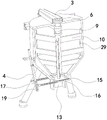
图1为本实用新型一种混凝土搅拌器的整体图。Fig. 1 is an overall view of a concrete mixer of the present invention.
图2为本实用新型一种混凝土搅拌器的爆炸图。Fig. 2 is an exploded view of a concrete mixer of the present invention.
图3为图2中A区域的放大示意图。FIG. 3 is an enlarged schematic diagram of area A in FIG. 2 .
图4为本实用新型一种混凝土搅拌器的剖视图。Fig. 4 is a sectional view of a concrete mixer of the present invention.
图5为本实用新型一种混凝土搅拌器的打开状态示意图。Fig. 5 is a schematic diagram of an open state of a concrete mixer of the present invention.
图中,部件名称与附图编号的对应关系为:In the figure, the corresponding relationship between component names and drawing numbers is:
1、罐体;2、顶盖;3、防护罩;4、转动杆;5、支撑柱;6、带轮;7、皮带;8、固定架;9、搅拌轴;10、搅拌叶;11、卡槽;12、固定筒;13、出料管;14、防滑垫;15、挡板;16、限位杆;17、横杆;18、压缩弹簧;19、通槽;20、电机;21、滑动块;22、固定槽;23、滑槽;24、防滑套;25、卡块;26、固定杆;27、橡胶套;28、套筒;29、刮板。1. Tank body; 2. Top cover; 3. Protective cover; 4. Rotating rod; 5. Support column; 6. Pulley; 7. Belt; 8. Fixed frame; 9. Stirring shaft; 10. Stirring blade; , card slot; 12, fixed cylinder; 13, discharge pipe; 14, anti-skid pad; 15, baffle; 16, limit rod; 17, cross bar; 18, compression spring; 19, through groove; 20, motor; 21, sliding block; 22, fixed groove; 23, chute; 24, anti-skid sleeve; 25, block; 26, fixed rod; 27, rubber sleeve; 28, sleeve; 29, scraper.
具体实施方式detailed description
下面结合附图和实施例对本实用新型的实施方式作进一步详细描述。以下实施例用于说明本实用新型,但不能用来限制本实用新型的范围。The implementation of the present utility model will be further described in detail below in conjunction with the accompanying drawings and examples. The following examples are used to illustrate the utility model, but cannot be used to limit the scope of the utility model.
实施例:Example:
如附图1至附图5所示:As shown in accompanying
本实用新型提供了一种混凝土搅拌器,包括罐体1与支撑柱5,罐体1顶端设置有顶盖2,罐体1内穿设有搅拌组件,罐体1底端设置有出料管13,出料管13内穿设的操纵组件包括转动杆4与挡板15,挡板15两侧设置的限位杆16穿设在出料管13上的固定筒12内,限位杆16上套设有压缩弹簧18,压缩弹簧18位于固定筒12一端连接,限位杆16末端设置的横杆17穿设在转动杆4上的通槽19内,转动杆4设置在罐体1上。向罐体1内添加胶凝材料、颗粒状集料与水,启动搅拌组件,对其进行搅拌,使其均匀混合,形成混凝土,排出混凝土时,工作人员只需要拉动转动杆4,使得转动杆4转动,通过通槽19挤压横杆17,从而使横杆17推动限位杆16在固定筒12内移动,限位杆16移动会带动挡板15移动,从而使挡板15伸出出料管13外,将出料管13打开,使得罐体1内的混凝土从出料管13排出,便于工作人员使用;松开转动杆4后,在压缩弹簧18的作用下,限位杆16复位,从而将挡板15插入出料管13内,将出料管13封闭,从而避免混凝土泄漏,实现装置的快速开闭,无需工作人员蹲在装置底部对装置进行开闭操作,使得装置操作更加方便,减轻工作人员的负担。The utility model provides a concrete mixer, comprising a
参考如图2与图4,搅拌组件包括电机20与搅拌轴9,电机20设置在罐体1侧面,电机20与搅拌轴9顶端均套设有带轮6,两组带轮6通过皮带7连接,搅拌轴9穿设在固定架8内,固定架8穿设在罐体1内,搅拌轴9上设置有多组搅拌叶10。将材料加入到罐体1后,启动电机20,通过带轮6与皮带7带动搅拌轴9旋转,从而通过多组搅拌叶10对材料进行搅拌,使其均匀混合在一起,形成混凝土,使得装置的搅拌效果更好。Referring to Fig. 2 and Fig. 4, the stirring assembly includes a
参考如图2与图4,顶盖2上设置有防护罩3,皮带7与带轮6均位于防护罩3内,搅拌叶10末端与刮板29连接,刮板29与罐体1内壁接触。通过防护罩3将皮带7与带轮6遮盖,避免工作人员误触而受伤,提高装置的安全性;刮板29可将附着在罐体1内壁的混凝土刮下,避免混凝土凝固在罐体1内壁上,导致材料浪费,并且不利于后续清理。Referring to Figure 2 and Figure 4, the
参考如图1与图3,顶盖2上设置有固定杆26,固定杆26上套设有橡胶套27,固定杆26与橡胶套27均穿设在套筒28内,套筒28设置在罐体1上。固定杆26穿在套筒28内,通过橡胶套27摩擦,避免固定杆26,从而将顶盖2靠的固定在罐体1面,取下顶盖2,只需要用力拉动固定杆26,使其退出套筒28,即可解除对顶盖2的锁定,便于工作人员将其取下,对装置内部进行清洗。Referring to Figure 1 and Figure 3, the
参考如图2与图3,顶盖2上设置有卡块25,卡块25卡设在卡槽11内,卡槽11开设在罐体1上。卡块25卡在卡槽11内,可避免顶盖2转动,对顶盖2起到辅助固定的作用,减轻固定杆26的负担,延长装置的使用寿命。Referring to FIG. 2 and FIG. 3 , the
参考如图3与图5,罐体1上的滑槽23内穿设有滑动块21,滑动块21上开设有固定槽22,固定槽22与转动杆4相适配。拉动转动杆4,将出料管13打开后,推动滑动块21,使得滑动块21上的固定槽22扣在转动杆4上,从而将转动杆4固定,无需工作人员一直拉住转动杆4,减轻工作人员的负担,使得装置使用更加轻松。Referring to Fig. 3 and Fig. 5, a sliding
参考如图2与图3,转动杆4顶端套设有防滑套24,支撑柱5底端设置有防滑垫14。防滑套24可避免工作人员出现手滑的情况,并且使工作人员手部与转动杆4之间为软接触,使工作人员感到更加舒适;防滑垫14可增大摩擦,避免装置出现位移,影响使用。Referring to Fig. 2 and Fig. 3, the top end of the
本实施例的具体使用方式与作用:使用装置时,向罐体1内添加各种材料,启动电机20,通过带轮6与皮带7带动搅拌轴9旋转,从而通过多组搅拌叶10对材料进行搅拌,使其均匀混合在一起,形成混凝土,排出混凝土时,工作人员只需要拉动转动杆4,通过通槽19挤压横杆17,从而使横杆17推动限位杆16在固定筒12内移动,从而使挡板15伸出出料管13外,将出料管13打开,使得罐体1内的混凝土从出料管13排出,便于工作人员使用;松开转动杆4后,在压缩弹簧18的作用下,限位杆16复位,从而将挡板15插入出料管13内,将出料管13封闭,实现装置的快速开闭,无需工作人员蹲在装置底部对装置进行开闭操作,使得装置操作更加方便,减轻工作人员的负担。The specific use and function of this embodiment: when using the device, add various materials to the
Claims (7)
Priority Applications (1)
| Application Number | Priority Date | Filing Date | Title |
|---|---|---|---|
| CN202222398758.8U CN218255908U (en) | 2022-09-09 | 2022-09-09 | concrete mixer |
Applications Claiming Priority (1)
| Application Number | Priority Date | Filing Date | Title |
|---|---|---|---|
| CN202222398758.8U CN218255908U (en) | 2022-09-09 | 2022-09-09 | concrete mixer |
Publications (1)
| Publication Number | Publication Date |
|---|---|
| CN218255908U true CN218255908U (en) | 2023-01-10 |
Family
ID=84713021
Family Applications (1)
| Application Number | Title | Priority Date | Filing Date |
|---|---|---|---|
| CN202222398758.8U Active CN218255908U (en) | 2022-09-09 | 2022-09-09 | concrete mixer |
Country Status (1)
| Country | Link |
|---|---|
| CN (1) | CN218255908U (en) |
Cited By (1)
| Publication number | Priority date | Publication date | Assignee | Title |
|---|---|---|---|---|
| CN118493610A (en) * | 2024-05-17 | 2024-08-16 | 上海克洛慧诚新材料科技有限公司 | A raw material stirring device for producing ceramic fiber composite materials |
-
2022
- 2022-09-09 CN CN202222398758.8U patent/CN218255908U/en active Active
Cited By (1)
| Publication number | Priority date | Publication date | Assignee | Title |
|---|---|---|---|---|
| CN118493610A (en) * | 2024-05-17 | 2024-08-16 | 上海克洛慧诚新材料科技有限公司 | A raw material stirring device for producing ceramic fiber composite materials |
Similar Documents
| Publication | Publication Date | Title |
|---|---|---|
| CN108202397B (en) | Ordinary concrete mixer is used in tunnel construction | |
| CN219849425U (en) | A raw material mixing device that prevents the discharge port from being clogged | |
| CN216099674U (en) | Concrete mixing device with cleaning function | |
| CN207204018U (en) | An ink mixer with a cleaning device | |
| CN217802456U (en) | Concrete mixing device for building construction | |
| CN217257230U (en) | Gypsum slurry stirring machine for gypsum powder production line | |
| CN218131257U (en) | Degradable sheet raw material mixing device | |
| CN216682744U (en) | A concrete mixer with the function of grading and filtering sand and gravel | |
| CN212170854U (en) | Concrete mixing device is used in road bridge construction | |
| CN206701790U (en) | A kind of hole washer | |
| CN214584698U (en) | A kind of concrete admixture performance testing device | |
| CN211587401U (en) | A concrete filter | |
| CN220918856U (en) | An easy-to-clean water-based acrylic resin dispersing and stirring device | |
| CN216458333U (en) | Mechanical automatic stirring device for easy cleaning | |
| CN103112190A (en) | Device and method for solid-liquid separation | |
| CN209775126U (en) | Mortar mixer convenient to wash | |
| CN209453889U (en) | A kind of aerated bricks waste material recovery device | |
| CN114768596A (en) | Gypsum mixing stirring device for orthopedics | |
| CN220807956U (en) | Concrete mixer device for road and bridge | |
| CN206633214U (en) | A kind of efficient cement mortar mixer | |
| CN218089926U (en) | A cotton blending machine with uniform density | |
| CN207628322U (en) | A kind of waterproofing agent combination mixing device | |
| CN220443598U (en) | Mixing hopper convenient to unpick and wash | |
| CN218496668U (en) | A performance check out test set for concrete | |
| CN214819709U (en) | A kind of stirring device for construction engineering |
Legal Events
| Date | Code | Title | Description |
|---|---|---|---|
| GR01 | Patent grant | ||
| GR01 | Patent grant |