CN218243594U - Mobile phone maintenance detection device - Google Patents
Mobile phone maintenance detection device Download PDFInfo
- Publication number
- CN218243594U CN218243594U CN202222043807.6U CN202222043807U CN218243594U CN 218243594 U CN218243594 U CN 218243594U CN 202222043807 U CN202222043807 U CN 202222043807U CN 218243594 U CN218243594 U CN 218243594U
- Authority
- CN
- China
- Prior art keywords
- type
- detection device
- mobile phone
- shaped
- seat
- Prior art date
- Legal status (The legal status is an assumption and is not a legal conclusion. Google has not performed a legal analysis and makes no representation as to the accuracy of the status listed.)
- Active
Links
- 238000001514 detection method Methods 0.000 title claims abstract description 23
- 238000012423 maintenance Methods 0.000 title claims description 16
- 238000000034 method Methods 0.000 description 4
- 230000005540 biological transmission Effects 0.000 description 1
- 230000007547 defect Effects 0.000 description 1
- 238000010586 diagram Methods 0.000 description 1
- 230000005489 elastic deformation Effects 0.000 description 1
Images


Landscapes
- Telephone Set Structure (AREA)
Abstract
The utility model belongs to the technical field of the cell-phone is maintained and is detected, especially, be a cell-phone is maintained detection device, it includes U type seat, the inner chamber has been seted up in the U type seat, the inner chamber internal rotation is provided with the connecting axle, the fixed gear that is provided with of one end of connecting axle, the outside of U type seat slides and is provided with two U type poles, and two U type poles all extend the inner chamber and the fixed fixture block that is provided with, and two fixture blocks are close to one side all fixed and are provided with the rack mutually, and two racks are close to one side all fixed and are provided with the rack, and the one end of two U type poles all extends all fixed L type support that is provided with on the U type seat. The utility model has the advantages of reasonable design, can conveniently realize pressing from both sides tight fixed to the cell-phone to can play the guard action to the cell-phone when pressing from both sides tightly, facilitate the use, the reliability is high.
Description
Technical Field
The utility model relates to a cell-phone is maintained and is detected technical field, especially relates to a cell-phone is maintained detection device.
Background
With the development of the times and the continuous progress of science and technology, mobile phones are changed continuously, the former mobile phones are all provided with keys, the existing mobile phones are provided with touch screens, the development is convenient for our lives step by step, the existing mobile phones can not be separated from the existing lives, the existing mobile phones are usually maintained and detected by directly placing the mobile phones on a desktop, then the mobile phones are maintained and detected by using tools of operators, but the mobile phones are not clamped and fixed in the maintenance and detection process, and the detection is easily influenced by the deviation of the mobile phones in the maintenance and detection process, so that the mobile phone maintenance and detection device is provided for solving the problems.
SUMMERY OF THE UTILITY MODEL
The utility model aims at solving the defects in the prior art, and providing a mobile phone maintenance and detection device.
In order to realize the purpose, the utility model adopts the following technical scheme:
the utility model provides a detection device is maintained to cell-phone, includes U type seat, the inner chamber has been seted up in the U type seat, the inner chamber internal rotation is provided with the connecting axle, the fixed gear that is provided with of one end of connecting axle, the outside of U type seat slides and is provided with two U type poles, and two U type poles all extend the inner chamber and fixed fixture block that is provided with, and two fixture blocks are close to one side fixed rack that is provided with all mutually, and two racks are close to one side fixed rack that is provided with all mutually, and the one end of two U type poles all extends on the U type seat and all fixes L type support that is provided with.
Preferably, an L-shaped plate is fixedly installed at the bottom side of the U-shaped seat, a screw rod is arranged in the L-shaped plate in a threaded mode, and a supporting plate is fixedly arranged at the top end of the screw rod.
Preferably, the front end of the connecting shaft extends to the front side of the U-shaped seat and is fixedly provided with a pulling plate.
Preferably, two sliding holes are formed in two sides of the U-shaped seat, and the two U-shaped rods are arranged in the corresponding sliding holes in a sliding mode.
Preferably, one side that two fixture blocks kept away from mutually all is fixed and is provided with the spring, and two springs are all fixed to be set up on the inner wall of inner chamber.
Preferably, rubber pads are fixedly arranged on the two L-shaped supports.
In the utility model, the mobile phone maintenance and detection device can conveniently realize the clamping and fixing of the mobile phone through the common matching of the U-shaped seat, the inner cavity, the connecting shaft, the pulling plate, the meshing transmission of the two racks and the gear, the two U-shaped rods, the two clamping blocks, the two springs, the two L-shaped supports and the two rubber pads, and can play a role in protecting the mobile phone when clamping, thereby solving the problem that the detection is influenced by the movement of the mobile phone easily in the maintenance and detection process in the prior art;
the utility model has the advantages of reasonable design, can conveniently realize pressing from both sides tight fixedly to the cell-phone to can play the guard action when pressing from both sides tightly, facilitate the use, the reliability is high.
Drawings
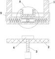
Fig. 1 is a schematic perspective view of a mobile phone maintenance and detection device provided by the present invention;
fig. 2 is a schematic structural diagram of a mobile phone maintenance and detection device provided by the present invention;
fig. 3 is a partially enlarged view of a portion a in fig. 2.
In the figure: 1. a U-shaped seat; 2. an L-shaped plate; 3. a screw; 4. a resisting plate; 5. an inner cavity; 6. a connecting shaft; 7. pulling a plate; 8. a gear; 9. a U-shaped rod; 10. a clamping block; 11. a rack; 12. a spring; 13. an L-shaped support; 14. and (7) a rubber pad.
Detailed Description
The technical solutions in the embodiments of the present invention will be described clearly and completely with reference to the accompanying drawings in the embodiments of the present invention, and it is obvious that the described embodiments are only some embodiments of the present invention, not all embodiments.
Referring to fig. 1-3, a mobile phone maintenance and detection device comprises a U-shaped seat 1, an inner cavity 5 is formed in the U-shaped seat 1, a connecting shaft 6 is arranged in the inner cavity 5 in a rotating manner, a gear 8 is fixedly arranged at one end of the connecting shaft 6, two U-shaped rods 9 are slidably arranged on the outer side of the U-shaped seat 1, the two U-shaped rods 9 extend into the inner cavity 5 and are fixedly provided with clamping blocks 10, racks 11 are fixedly arranged on one sides, close to each other, of the two racks 11, and L-shaped supports 13 are fixedly arranged on one ends of the two U-shaped rods 9, which extend onto the U-shaped seat 1.
In this embodiment, the bottom side of the U-shaped seat 1 is fixedly provided with an L-shaped plate 2, the screw 3 is arranged in the L-shaped plate 2, and the top end of the screw 3 is fixedly provided with a support plate 4, so that the U-shaped seat 1 can be conveniently fixed on a desktop.
In this embodiment, the front end of the connecting shaft 6 extends to the front side of the U-shaped seat 1 and is fixedly provided with the pulling plate 7, so that the connecting shaft 6 can be conveniently pulled manually to rotate.
In this embodiment, two sliding holes are respectively formed in two sides of the U-shaped seat 1, and the two U-shaped rods 9 are slidably disposed in the corresponding sliding holes, so that the two U-shaped rods 9 can be conveniently slidably disposed.
In this embodiment, one side that two fixture blocks 10 kept away from mutually all fixedly is provided with spring 12, and two springs 12 all fixedly set up on the inner wall of inner chamber 5, can make things convenient for the removal that resets of two fixture blocks 10.
In this embodiment, the two L-shaped supports 13 are both fixedly provided with rubber pads 14, which can protect the mobile phone during the clamping process.
The utility model discloses in, when using, can be through placing U type seat 1 on the desktop, and with L template 2 card on the desktop, then can be through manual rotating screw rod 3, make it drive and support board 4 and desktop looks butt, can fix U type seat 1, then can drive arm-tie 7 anticlockwise rotation through manual pulling, can make it drive gear 8 anticlockwise rotation through connecting axle 6, thereby can promote two fixture blocks 10 through two racks 11 and keep away from the removal mutually, make it can extrude corresponding spring 12, can drive two L type supports 13 through two U type poles 9 simultaneously and keep away from the removal mutually, then can place the collection that needs to maintain the detection on two L type supports 13, then release arm-tie 7, can make it pass through the elastic deformation of two springs 12, can make two L type supports 13 be close to the removal and reset mutually, make it can press from both sides tight fixedly to the cell-phone through two L type supports 13, and can play the guard action to the cell-phone through two rubber pads 14.
The basic principles and the main features of the invention and the advantages of the invention have been shown and described above, it will be evident to those skilled in the art that the invention is not limited to the details of the foregoing illustrative embodiments, but that the invention may be embodied in other specific forms without departing from the spirit or essential characteristics thereof. The present embodiments are therefore to be considered in all respects as illustrative and not restrictive, the scope of the invention being indicated by the appended claims rather than by the foregoing description, and all changes which come within the meaning and range of equivalency of the claims are therefore intended to be embraced therein. Any reference sign in a claim should not be construed as limiting the claim concerned.
Furthermore, it should be understood that although the present specification describes embodiments, not every embodiment includes only a single embodiment, and such description is for clarity purposes only, and it is to be understood that all embodiments may be combined as appropriate by one of ordinary skill in the art to form other embodiments as will be apparent to those of skill in the art from the description herein.
Claims (6)
1. The utility model provides a detection device is maintained to cell-phone, includes U type seat (1), its characterized in that, inner chamber (5) have been seted up in U type seat (1), inner chamber (5) internal rotation is provided with connecting axle (6), the fixed gear (8) that is provided with of one end of connecting axle (6), the outside of U type seat (1) is slided and is provided with two U type poles (9), and two U type poles (9) all extend inner chamber (5) and fixed be provided with fixture block (10), and one side that two fixture block (10) are close to mutually all fixedly is provided with rack (11), and one side that two rack (11) are close to mutually all fixedly is provided with rack (11), and the one end of two U type poles (9) all extends on U type seat (1) and all fixedly is provided with L type support (13).
2. The mobile phone maintenance and detection device according to claim 1, wherein an L-shaped plate (2) is fixedly installed at the bottom side of the U-shaped seat (1), a screw (3) is arranged on an internal thread of the L-shaped plate (2), and a support plate (4) is fixedly arranged at the top end of the screw (3).
3. The mobile phone maintenance and detection device according to claim 1, wherein the front end of the connecting shaft (6) extends to the front side of the U-shaped seat (1) and is fixedly provided with a pulling plate (7).
4. The mobile phone maintenance and detection device according to claim 1, wherein two sliding holes are formed in both sides of the U-shaped seat (1), and the two U-shaped rods (9) are slidably disposed in the corresponding sliding holes.
5. The mobile phone maintenance detection device according to claim 1, wherein the two clamping blocks (10) are fixedly provided with springs (12) at the sides far away from each other, and the two springs (12) are fixedly provided on the inner wall of the inner cavity (5).
6. The mobile phone maintenance detection device according to claim 1, wherein the two L-shaped supports (13) are respectively and fixedly provided with a rubber pad (14).
Priority Applications (1)
| Application Number | Priority Date | Filing Date | Title |
|---|---|---|---|
| CN202222043807.6U CN218243594U (en) | 2022-08-04 | 2022-08-04 | Mobile phone maintenance detection device |
Applications Claiming Priority (1)
| Application Number | Priority Date | Filing Date | Title |
|---|---|---|---|
| CN202222043807.6U CN218243594U (en) | 2022-08-04 | 2022-08-04 | Mobile phone maintenance detection device |
Publications (1)
| Publication Number | Publication Date |
|---|---|
| CN218243594U true CN218243594U (en) | 2023-01-06 |
Family
ID=84679951
Family Applications (1)
| Application Number | Title | Priority Date | Filing Date |
|---|---|---|---|
| CN202222043807.6U Active CN218243594U (en) | 2022-08-04 | 2022-08-04 | Mobile phone maintenance detection device |
Country Status (1)
| Country | Link |
|---|---|
| CN (1) | CN218243594U (en) |
-
2022
- 2022-08-04 CN CN202222043807.6U patent/CN218243594U/en active Active
Similar Documents
| Publication | Publication Date | Title |
|---|---|---|
| CN214999084U (en) | Electromechanical device damping device | |
| CN218697836U (en) | Handicraft fixing device | |
| CN218658645U (en) | Composite battery box sealing performance test detection fixing tool | |
| CN219854075U (en) | Display screen detection jig aluminum profile limiting frame | |
| CN216971481U (en) | Pole piece cold pressing wrinkle-proof device | |
| CN214671496U (en) | Warning sign convenient to place for electric power engineering construction | |
| CN216714899U (en) | Quick corner connector for connecting hollow frame | |
| CN215283353U (en) | Smart mobile phone film pasting equipment | |
| CN214075992U (en) | A quick-plug hollow fiber curtain membrane | |
| CN212824843U (en) | Anchor clamps are used in processing of cell-phone display screen | |
| CN212000119U (en) | A wire guide device for a circular knitting machine | |
| CN216559604U (en) | Elasticity detection device is used in spring production and processing with protection machanism | |
| CN109910675B (en) | But new energy automobile quick replacement battery | |
| CN219750021U (en) | Split bicycle mating joint | |
| CN208432348U (en) | A kind of spring dynamometer being conveniently replaceable spring | |
| CN222040403U (en) | A high-stability automobile control panel frame | |
| CN222429019U (en) | Punching device for processing mobile phone support | |
| CN216801908U (en) | A fixing device for metal filter mesh processing | |
| CN220362471U (en) | Clamping device for gold processing | |
| CN215768355U (en) | Natural gas heat value tester | |
| CN222932612U (en) | Display screen assembly production facility | |
| CN219282262U (en) | Bearing clamping structure of rotary antenna tower turntable | |
| CN217877859U (en) | Direct-reading water meter convenient for cleaning dirt | |
| CN221287210U (en) | Rock wool filter chamber picture peg changes structure | |
| CN220988156U (en) | Wall chart rack |
Legal Events
| Date | Code | Title | Description |
|---|---|---|---|
| GR01 | Patent grant | ||
| GR01 | Patent grant |