CN218224205U - Hot-pressing mechanism for glasses case - Google Patents
Hot-pressing mechanism for glasses case Download PDFInfo
- Publication number
- CN218224205U CN218224205U CN202222279940.1U CN202222279940U CN218224205U CN 218224205 U CN218224205 U CN 218224205U CN 202222279940 U CN202222279940 U CN 202222279940U CN 218224205 U CN218224205 U CN 218224205U
- Authority
- CN
- China
- Prior art keywords
- locating part
- spectacle case
- sliding plate
- piece
- board
- Prior art date
- Legal status (The legal status is an assumption and is not a legal conclusion. Google has not performed a legal analysis and makes no representation as to the accuracy of the status listed.)
- Active
Links
- 230000007246 mechanism Effects 0.000 title claims abstract description 18
- 239000011521 glass Substances 0.000 title claims description 8
- 238000007731 hot pressing Methods 0.000 title claims description 7
- 241000510164 Cumberlandia monodonta Species 0.000 claims abstract description 30
- 238000009434 installation Methods 0.000 claims abstract description 25
- 238000003825 pressing Methods 0.000 claims abstract description 16
- 238000010438 heat treatment Methods 0.000 claims abstract description 8
- 239000013013 elastic material Substances 0.000 claims description 3
- 239000000463 material Substances 0.000 claims description 3
- 238000004519 manufacturing process Methods 0.000 description 5
- 238000001125 extrusion Methods 0.000 description 4
- 238000000034 method Methods 0.000 description 3
- 230000004048 modification Effects 0.000 description 2
- 238000012986 modification Methods 0.000 description 2
- 230000008859 change Effects 0.000 description 1
- 238000006073 displacement reaction Methods 0.000 description 1
- 230000006872 improvement Effects 0.000 description 1
- 239000012535 impurity Substances 0.000 description 1
- 238000004080 punching Methods 0.000 description 1
Images


Landscapes
- Automatic Assembly (AREA)
Abstract
The utility model provides a hot press mechanism for spectacle case relates to hot press mechanism field, a hot press mechanism for spectacle case, include board, support frame, drive actuating cylinder, gag lever post, sliding plate, installation piece, pressing piece, locating part, pressing piece demountable installation in the installation piece, the locating part install in on the board, be provided with the spacing groove on the locating part, the inside heating element that is provided with of locating part, the utility model discloses when using, place the spectacle case in the spacing groove, then heat the spectacle case of spacing inslot portion through heating element, later drive the sliding plate through driving actuating cylinder, the sliding plate drives installation piece and pressing piece, extrudees the spectacle case of mounting groove inside, extrudees the spectacle case into the shape of spacing groove, the utility model discloses an extruded article and locating part can be changed, can produce the spectacle case of different shapes, and the utility model discloses simple structure, reasonable in design, convenient to use.
Description
Technical Field
The application relates to the field of hot pressing mechanisms, in particular to a hot pressing mechanism for a glasses case.
Background
The spectacle case need extrude the limit portion of spectacle case at the in-process of processing, and need heat at the extruded in-process, and present extrusion equipment can't change extruded part for the spectacle case style of finished product is single, and present extrusion equipment, and the structure is complicated, and manufacturing cost is higher.
Disclosure of Invention
An object of the embodiment of the application is to provide a hot pressing mechanism for spectacle case, which can solve the technical problems of single production style and complex production equipment structure of the spectacle case.
The embodiment of the application provides a hot pressing mechanism for spectacle case, include board, support frame, drive actuating cylinder, gag lever post, sliding plate, installation piece, pressing piece, locating part, the support frame is installed on the board, the gag lever post install in the support frame with between the board, sliding plate slidable mounting in on the gag lever post, it is used for the drive to drive actuating cylinder the sliding plate along the gag lever post reciprocates, the installation piece set up in the sliding plate lower extreme, press piece demountable installation in the installation piece, the locating part install in on the board, be provided with the spacing groove on the locating part, the pressing piece set up in directly over the spacing groove, the inside heating element that is provided with of locating part.
Preferably, the number of the pressing pieces is two, and the limiting piece is provided with two limiting grooves.
Preferably, the limiting part left and right sides is provided with limiting post, the limiting part demountable installation in the board upper end.
Preferably, four limiting rods are arranged, and the limiting rods are distributed at four top corners of the sliding plate.
Preferably, supporting legs are arranged below the machine table, the number of the supporting legs is at least four, and buffer blocks are arranged below the supporting legs and made of elastic materials.
Preferably, handles are arranged on the left side and the right side of the machine table.
Preferably, the left side and the right side of the support frame are provided with protection plates, and the protection plates are made of high-temperature-resistant materials.
The utility model has the advantages that:
the utility model provides a pair of a hot press mechanism for spectacle case, include board, support frame, drive actuating cylinder, gag lever post, sliding plate, installation piece, pressing piece, locating part, the support frame is installed on the board, the gag lever post install in the support frame with between the board, the sliding plate slidable mounting in on the gag lever post, it is used for the drive to drive actuating cylinder the sliding plate along the gag lever post reciprocates, the installation piece set up in the sliding plate lower extreme, press piece demountable installation in install in the installation piece, the locating part install in on the board, be provided with the spacing groove on the locating part, press piece set up in directly over the spacing groove, the inside heating element that is provided with of locating part, the utility model discloses when using, place the spectacle case in the spacing groove, then heat the spectacle case of spacing inslot portion through heating element, later drive the sliding plate through driving actuating cylinder and press the pressing piece, the sliding plate drives installation piece and extrudees the spectacle case inside the mounting groove, extrudees the shape of spectacle case spacing groove, the utility model discloses an extruded article and locating part can be changed, can produce the spectacle case of different shapes of production, and the utility model discloses simple structure, reasonable in design, convenient to use.
Drawings
In order to more clearly illustrate the technical solutions of the embodiments of the present application, the drawings that are required to be used in the embodiments will be briefly described below, it should be understood that the following drawings only illustrate some embodiments of the present application and therefore should not be considered as limiting the scope, and for those skilled in the art, other related drawings can be obtained from the drawings without inventive effort.
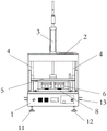
FIG. 1 is a schematic view of the present invention;
fig. 2 is a front view of the present invention;
fig. 3 is a cross-sectional view of the present invention.
The reference numerals are respectively:
the device comprises a machine table (1), a support frame (2), a driving cylinder (3), a limiting rod (4), a sliding plate (5), an installation block (6), a pressing piece (7), a limiting piece (8), a limiting groove (9), a limiting column (10), a supporting leg (11), a buffer block (12), a handle (13) and a protection plate (14).
Detailed Description
In order to make the objects, technical solutions and advantages of the embodiments of the present application clearer, the technical solutions in the embodiments of the present application will be clearly and completely described below with reference to the drawings in the embodiments of the present application, and it is obvious that the described embodiments are some embodiments of the present application, but not all embodiments. The components of the embodiments of the present application, as generally described and illustrated in the figures herein, could be arranged and designed in a wide variety of different configurations.
Thus, the following detailed description of the embodiments of the present application, presented in the accompanying drawings, is not intended to limit the scope of the claimed application, but is merely representative of selected embodiments of the application. All other embodiments, which can be derived by a person skilled in the art from the embodiments given herein without making any creative effort, shall fall within the protection scope of the present application.
It should be noted that: like reference numbers and letters refer to like items in the following figures, and thus, once an item is defined in one figure, it need not be further defined and explained in subsequent figures.
In the description of the present application, it should be noted that the terms "center", "upper", "lower", "left", "right", "vertical", "horizontal", "inner", "outer", and the like indicate orientations or positional relationships based on the orientations or positional relationships shown in the drawings or orientations or positional relationships that the products of the application usually place when in use, and are used only for convenience in describing the present application and simplifying the description, but do not indicate or imply that the devices or elements being referred to must have a specific orientation, be constructed and operated in a specific orientation, and thus, should not be construed as limiting the present application. Furthermore, the terms "first," "second," "third," and the like are used solely to distinguish one from another and are not to be construed as indicating or implying relative importance.
Furthermore, the terms "horizontal", "vertical", "suspended" and the like do not imply that the components are absolutely horizontal or suspended, but may be slightly inclined. For example, "horizontal" merely means that the direction is more horizontal than "vertical" and does not mean that the structure must be perfectly horizontal, but may be slightly inclined.
In the description of the present application, it is further noted that, unless expressly stated or limited otherwise, the terms "disposed," "mounted," "connected," and "connected" are to be construed broadly, e.g., as meaning either a fixed connection, a removable connection, or an integral connection; can be mechanically or electrically connected; they may be connected directly or indirectly through intervening media, or they may be interconnected between two elements. The specific meaning of the above terms in the present application can be understood in a specific case by those of ordinary skill in the art.
As shown in fig. 1-3, a hot press mechanism for spectacle case, include board 1, support frame 2, drive actuating cylinder 3, gag lever post 4, sliding plate 5, installation piece 6, pressing member 7, locating part 8, support frame 2 installs on board 1, gag lever post 4 install in support frame 2 with between the board 1, but sliding plate 5 slidable mounting in on the gag lever post 4, drive actuating cylinder 3 be used for the drive the sliding plate 5 along gag lever post 4 reciprocates, installation piece 6 set up in the sliding plate 5 lower extreme, pressing member 7 demountable mounting in installation piece 6, locating part 8 install in on board 1, be provided with spacing groove 9 on the locating part 8, pressing member 7 set up in directly over spacing groove 9, the inside heating element that is provided with of locating part 8, the utility model discloses when using, place the spectacle case in spacing groove 9, then heat the spectacle case inside the spacing groove 9 through heating element, later drive sliding plate 5 through drive actuating cylinder 3, sliding plate 5 drives installation piece 6 and pressing member 7, extrudes the mounting groove inside spectacle case, with the practical shape of the spectacle case 9 of changing, the utility model discloses the shape of spectacle case can be produced the extrusion piece and the utility model is reasonable in the utility model and the utility model is convenient for the use, and the utility model is simple design and the utility model is used.
As shown in fig. 1, in this embodiment, the pressing member 7 is provided with two, and the limiting member 8 is provided with two limiting grooves 9, so that the present invention can produce two glasses cases at a time, and can improve the production efficiency of the glasses cases.
In this embodiment, the locating part 8 left and right sides is provided with spacing post 10, locating part 8 demountable installation in 1 upper end of board, the utility model discloses a spacing post 10 can play limiting displacement to locating part 8, prevents that locating part 8 from taking place to shift at the extruded in-process.
As shown in fig. 1, in this embodiment, in order to make the sliding plate 5 run up and down smoothly, four limiting rods 4 are provided, and the limiting rods 4 are distributed at four top corners of the sliding plate 5.
As shown in fig. 1, in this embodiment, board 1 below is provided with supporting legs 11, supporting legs 11 are provided with four at least, supporting legs 11 below is provided with buffer block 12, buffer block 12 adopts the elastic material to make, the utility model discloses a buffer block 12 can alleviate the punching press power that drives actuating cylinder 3 extrusion spectacle case to ground or desktop.
As shown in fig. 1-2, in this embodiment, in order to facilitate the movement of the present invention, handles 13 are disposed on the left and right sides of the machine table 1, and before the use of the present invention, the present invention is installed on the ground or on the desktop.
As shown in fig. 1 and 3, in the embodiment, the left and right sides of the supporting frame 2 are provided with the protection plates 14, the protection plates 14 are made of high temperature resistant materials, and the protection plates 14 can prevent impurities from entering the limiting groove 9 from the side.
The above description is only a preferred embodiment of the present application and is not intended to limit the present application, and various modifications and changes may be made by those skilled in the art. Any modification, equivalent replacement, improvement and the like made within the spirit and principle of the present application shall be included in the protection scope of the present application.
Claims (7)
1. The utility model provides a hot pressing mechanism for spectacle case which characterized in that: including board, support frame, drive actuating cylinder, gag lever post, sliding plate, installation piece, pressing piece, locating part, the support frame is installed on the board, the gag lever post install in the support frame with between the board, the sliding plate slidable mounting in on the gag lever post, it is used for the drive to drive actuating cylinder the sliding plate along the gag lever post reciprocates, the installation piece set up in the sliding plate lower extreme, press piece demountable installation in the installation piece, the locating part install in on the board, be provided with the spacing groove on the locating part, press the piece set up in directly over the spacing groove, the inside heating element that is provided with of locating part.
2. A heat and pressure mechanism for spectacle case according to claim 1 wherein: the pressing piece is provided with two, be provided with two spacing grooves on the locating part.
3. The heat press mechanism for glasses case as set forth in claim 1, wherein: the locating part left and right sides is provided with spacing post, locating part demountable installation in board upper end.
4. A heat and pressure mechanism for spectacle case according to claim 1 wherein: the limiting rods are arranged in four numbers, and the limiting rods are distributed at four top corners of the sliding plate.
5. The heat press mechanism for glasses case as set forth in claim 1, wherein: the supporting legs are arranged below the machine table and are at least four, and the buffer blocks are arranged below the supporting legs and are made of elastic materials.
6. The heat press mechanism for glasses case as set forth in claim 1, wherein: handles are arranged on the left side and the right side of the machine table.
7. A heat and pressure mechanism for spectacle case according to claim 1 wherein: the support frame left and right sides is provided with the guard plate, the guard plate adopts high temperature resistant material to make.
Priority Applications (1)
| Application Number | Priority Date | Filing Date | Title |
|---|---|---|---|
| CN202222279940.1U CN218224205U (en) | 2022-08-26 | 2022-08-26 | Hot-pressing mechanism for glasses case |
Applications Claiming Priority (1)
| Application Number | Priority Date | Filing Date | Title |
|---|---|---|---|
| CN202222279940.1U CN218224205U (en) | 2022-08-26 | 2022-08-26 | Hot-pressing mechanism for glasses case |
Publications (1)
| Publication Number | Publication Date |
|---|---|
| CN218224205U true CN218224205U (en) | 2023-01-06 |
Family
ID=84685559
Family Applications (1)
| Application Number | Title | Priority Date | Filing Date |
|---|---|---|---|
| CN202222279940.1U Active CN218224205U (en) | 2022-08-26 | 2022-08-26 | Hot-pressing mechanism for glasses case |
Country Status (1)
| Country | Link |
|---|---|
| CN (1) | CN218224205U (en) |
-
2022
- 2022-08-26 CN CN202222279940.1U patent/CN218224205U/en active Active
Similar Documents
| Publication | Publication Date | Title |
|---|---|---|
| CN209971047U (en) | Pressing die for producing refractory material | |
| CN209174706U (en) | Adjustable leaf spring end bending die | |
| CN110757582B (en) | A cloth punching machine for plastic balls | |
| CN215657359U (en) | Lifting stamping device | |
| CN215036892U (en) | Hardware stamping die fixing device | |
| CN209631973U (en) | A kind of stamping die of no bending trace | |
| CN117086172A (en) | A stamping and shaping device for metal plate processing | |
| CN211052310U (en) | Device for stamping lamp tube contact by double points | |
| CN114433718A (en) | Door shell door handle forming equipment | |
| CN209536204U (en) | A kind of Double-bridge type rice cake machine transmission mechanism | |
| CN208866274U (en) | A kind of positioning device of lamp stamping mold | |
| CN218638306U (en) | Aluminum alloy disk production stamping device | |
| CN216175949U (en) | Novel many connecting rods punching press mechanism | |
| CN208373952U (en) | A kind of molding die of embossing perforation meson | |
| CN214239717U (en) | Product industrial design mold processing | |
| CN219112686U (en) | Stamping forming die for machining special-shaped piece | |
| CN222327958U (en) | Up-down positioning compressing mechanism | |
| CN220329653U (en) | Bending machine for manufacturing copper bars of electrical control cabinet | |
| CN212884410U (en) | Plate processing die | |
| CN221064239U (en) | Quick-change forming module | |
| CN215508539U (en) | A stamping device for sheet metal production | |
| CN213496030U (en) | Stamping die is used in production of five metals stainless steel articles for use | |
| CN214725847U (en) | Suction nozzle pressure forming device | |
| CN216989393U (en) | Stamping die is used in treadmill base production | |
| CN220561746U (en) | Stamping equipment for paperboard forming |
Legal Events
| Date | Code | Title | Description |
|---|---|---|---|
| GR01 | Patent grant | ||
| GR01 | Patent grant |