CN218193619U - Bush processing machine of impressing - Google Patents
Bush processing machine of impressing Download PDFInfo
- Publication number
- CN218193619U CN218193619U CN202222110084.7U CN202222110084U CN218193619U CN 218193619 U CN218193619 U CN 218193619U CN 202222110084 U CN202222110084 U CN 202222110084U CN 218193619 U CN218193619 U CN 218193619U
- Authority
- CN
- China
- Prior art keywords
- plate
- sets
- bush
- bushing
- groups
- Prior art date
- Legal status (The legal status is an assumption and is not a legal conclusion. Google has not performed a legal analysis and makes no representation as to the accuracy of the status listed.)
- Active
Links
- 238000003754 machining Methods 0.000 claims description 10
- 238000000034 method Methods 0.000 abstract description 5
- 238000005516 engineering process Methods 0.000 abstract description 2
- 230000002457 bidirectional effect Effects 0.000 description 11
- 230000000694 effects Effects 0.000 description 6
- 230000002349 favourable effect Effects 0.000 description 2
- 238000005299 abrasion Methods 0.000 description 1
- 230000009286 beneficial effect Effects 0.000 description 1
- 238000009434 installation Methods 0.000 description 1
- 238000007789 sealing Methods 0.000 description 1
- 239000013589 supplement Substances 0.000 description 1
Images




Landscapes
- Jigs For Machine Tools (AREA)
Abstract
The utility model discloses a bush processing machine of impressing relates to bush processing technology field. The bushing processing press-in machine comprises a bottom plate, a clamping mechanism and a supporting mechanism, wherein a pressing plate is arranged right above the bottom plate, a vertical plate is fixedly mounted at the top of the bottom plate, and the supporting mechanism is arranged in the vertical plate. This bush processing machine of impressing, can be when in the mechanical parts that impresses at bush body through supporting mechanism, support its horizontal direction, make it evenly avoid warping at the whole atress of pushing down the process, the machine of impressing that current part is used for impressing has been solved, at the in-process of pushing down the bush, the bush does not have holding power at the horizontal direction, the effort that leads to it to receive at the horizontal direction can make the bush produce and warp, and then can not continue to impress, cause the problem of the loss of cost, the quality of bush body has been guaranteed, the stability of device has been improved, the practicality of device has been promoted.
Description
Technical Field
The utility model relates to a bush processing technology field, in particular to bush processing press.
Background
The bushing is a matching part used outside a mechanical workpiece to achieve the effects of sealing, abrasion protection and the like, and is a ring sleeve playing a role of a gasket, and is required to be pressed into the mechanical workpiece to realize installation in the machining process of the bushing.
SUMMERY OF THE UTILITY MODEL
An object of the utility model is to solve one of the technical problem that exists among the prior art at least, provide a bush processing machine of impressing, probably produce the problem of deformation when can solving current partial bush and impressing.
In order to achieve the above object, the utility model provides a following technical scheme: a bushing-machining press comprising:
the pressing plate is arranged right above the bottom plate, and the vertical plate is fixedly arranged at the top of the bottom plate;
the clamping mechanism is arranged right above the pressing plate and used for replacing the pressing plate;
the supporting mechanism sets up in the inside of riser, and the supporting mechanism includes motor, connecting plate and supporting wheel, and one side inner wall fixed mounting of riser has the motor, and the front side of riser is provided with two sets of connecting plates, respectively rotates between the front and back side inner wall of two sets of connecting plates and installs a set of supporting wheel, and the motor is used for driving two sets of supporting wheel and removes.
Preferably, the supporting mechanism further comprises a bidirectional screw and a threaded block, the bidirectional screw is rotatably installed between the inner wall of the other side of the vertical plate, the rotating shaft of the motor is fixedly connected with the bidirectional screw, two groups of threaded blocks are installed on the bidirectional screw in a threaded mode, two groups of connecting grooves are formed in the front side of the vertical plate, two groups of connecting plates are respectively fixedly connected with the two groups of threaded blocks through the connecting grooves, and the two groups of connecting plates are respectively attached to the inner walls of the two groups of connecting grooves.
Preferably, the mechanism that clamps includes mounting panel, limiting plate, dog, cardboard, baffle and adjusting button, be provided with the mounting panel directly over the clamp plate, the mounting groove has been seted up to the bottom of mounting panel, the top fixed mounting of clamp plate has the limiting plate, the limiting plate laminates with the inner wall of mounting groove mutually, one side of mounting panel is provided with the dog, one side external fixed surface of dog installs the cardboard, the cardboard runs through the mounting panel and the opposite side that the limiting plate extends to the mounting panel, one side surface of mounting panel rotates and installs the baffle, the baffle laminates with the opposite side surface of dog mutually, one side external fixed surface of baffle installs the adjusting button.
Preferably, the top fixed mounting of bottom plate has two sets of thread bushings, and each thread mounting has a set of threaded rod on two sets of thread bushings, and each fixed mounting of one end of two sets of threaded rods has a set of knob, and the other end of two sets of threaded rods respectively rotates and installs a set of splint, has reached and has carried out the fixed effect of centre gripping to mechanical workpiece.
Preferably, the outer surface of the front side of the vertical plate is fixedly provided with a hanging plate, the bottom of the hanging plate is fixedly provided with a hydraulic rod, and the mounting plate is fixedly arranged at the free end of the hydraulic rod.
Preferably, a mechanical workpiece is mounted on the top of the bottom plate, a press-in groove is formed in the top of the mechanical workpiece, and a bushing body is mounted on the top of the mechanical workpiece.
Preferably, the bottom of clamp plate and the surface of two sets of supporting wheels respectively fixed mounting have a set of rubber pad, have reached and have increased the effect that supports and the frictional force of impressing in order to avoid sliding.
Compared with the prior art, the beneficial effects of the utility model are that:
(1) This bush processing machine of impressing, can be when in the mechanical parts that impresses at bush body through supporting mechanism, support its horizontal direction, make it evenly avoid being out of shape pushing down the whole atress of process, the machine of impressing that current part is used for impressing has been solved, at the in-process of pushing down the bush, the bush does not have holding power at the horizontal direction, the effort that leads to it to receive at the horizontal direction can make the bush produce and warp, and then can not continue to impress, cause the problem of the loss of cost, the quality of bush body has been guaranteed, the stability of device has been improved, the practicality of device has been promoted.
(2) This bush processing machine of impressing can be convenient for tear open the clamp plate through clamping the mechanism and trade, makes it when pushing down not unidimensional bush body, can change to blockking the support of supporting wheel pair bush body with avoiding great size with the size, can enough improve the efficiency of impressing of device, has also improved the flexibility of device, has guaranteed the result of use of device, is favorable to the popularization and the use of device.
Drawings
The invention will be further described with reference to the following figures and examples:
fig. 1 is a cross-sectional view of the present invention;
fig. 2 is a front view of the present invention;
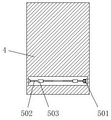
fig. 3 is a sectional view of the vertical plate of the present invention;
FIG. 4 is an enlarged view of the part A of the present invention;
fig. 5 is an enlarged view of the position B of the present invention.
Reference numerals: 1. a base plate; 2. a mechanical workpiece; 3. a bushing body; 4. a vertical plate; 5. a support mechanism; 501. a motor; 502. a bidirectional screw; 503. a thread block; 504. a connecting plate; 505. a support wheel; 6. a hanger plate; 7. a hydraulic lever; 8. a clamping mechanism; 801. mounting a plate; 802. a limiting plate; 803. a stopper; 804. clamping a plate; 805. a baffle plate; 806. an adjusting knob; 9. pressing a plate; 10. a threaded sleeve; 11. a threaded rod; 12. a knob; 13. and (4) clamping the plate.
Detailed Description
This section will describe in detail the embodiments of the present invention, preferred embodiments of the present invention are shown in the attached drawings, which are used to supplement the description of the text part of the specification with figures, so that one can intuitively and vividly understand each technical feature and the whole technical solution of the present invention, but they cannot be understood as the limitation of the protection scope of the present invention.
Referring to fig. 1-5, the present invention provides a technical solution: a bush machining press-in machine comprises a bottom plate 1, a clamping mechanism 8 and a supporting mechanism 5, wherein a pressing plate 9 is arranged right above the bottom plate 1, a vertical plate 4 is fixedly installed at the top of the bottom plate 1, the clamping mechanism 8 is arranged right above the pressing plate 9, the clamping mechanism 8 is used for replacing the pressing plate 9, two groups of threaded sleeves 10 are fixedly installed at the top of the bottom plate 1, a group of threaded rods 11 are installed on each group of threaded sleeves 10 in a threaded mode, a group of knobs 12 are fixedly installed at one ends of the two groups of threaded rods 11 respectively, a group of clamping plates 13 are rotatably installed at the other ends of the two groups of threaded rods 11 respectively, a mechanical workpiece 2 is installed at the top of the bottom plate 1, a press-in groove is formed at the top of the mechanical workpiece 2, and a bush body 3 is installed at the top of the mechanical workpiece 2;
the supporting mechanism 5 is arranged inside the vertical plate 4, the supporting mechanism 5 comprises a motor 501, a connecting plate 504 and supporting wheels 505, the motor 501 is fixedly mounted on the inner wall of one side of the vertical plate 4, two sets of connecting plates 504 are arranged on the front side of the vertical plate 4, a set of supporting wheels 505 are rotatably mounted between the inner walls of the front side and the rear side of the two sets of connecting plates 504, and the motor 501 is used for driving the two sets of supporting wheels 505 to move.
The supporting mechanism 5 further comprises a bidirectional screw 502 and a threaded block 503, the bidirectional screw 502 is rotatably installed between the inner wall of the other side of the vertical plate 4, a rotating shaft of the motor 501 is fixedly connected with the bidirectional screw 502, two sets of threaded blocks 503 are installed on the bidirectional screw 502 in a threaded manner, two sets of connecting grooves are formed in the front side of the vertical plate 4, two sets of connecting plates 504 are fixedly connected with the two sets of threaded blocks 503 through the connecting grooves respectively, the two sets of connecting plates 504 are attached to the inner walls of the two sets of connecting grooves respectively, a set of rubber pads are fixedly installed on the bottom of the pressing plate 9 and the outer surfaces of the two sets of supporting wheels 505 respectively, and under the effect of the supporting mechanism 5, when the bushing body 3 is pressed into the mechanical workpiece 2, the bushing body is supported in the horizontal direction, so that the whole stress is prevented from being deformed in the pressing-down process, the quality of the bushing body 3 is guaranteed, the stability of the device is improved, and the practicability of the device is improved.
The working principle is as follows: when the device is used, a mechanical workpiece 2 is placed on the top of a bottom plate 1, a threaded rod 11 is rotated through a knob 12 to drive clamping plates 13 to move on the bottom plate 1, so that the two groups of clamping plates 13 clamp and fix the mechanical workpiece 2, a bushing body 3 is aligned with a press-in groove on the mechanical workpiece 2 to be placed, an adjusting button 806 is rotated to drive a baffle 805 to rotate so as not to block a stop 803, the clamping plate 804 can be drawn out, the pressing plate 9 with a corresponding size is replaced by a pressing plate 9 with a corresponding size and is installed on a mounting plate 801 through a limiting plate 802, then the free end of a hydraulic rod 7 is controlled to extend to drive a pressing plate 9 downward moving device to be attached to the top of the bushing body 3, a control motor 501 is started to drive a bidirectional screw rod 502 to rotate, the bidirectional screw rod 502 drives a threaded block 503 thereon to move so that a connecting plate 504 connected with the threaded block 503 drives a supporting wheel 505 to clamp and support the bushing body 3, and at the moment, the free end of the hydraulic rod 7 is controlled to continue to extend and press into the bushing body 3 into the mechanical workpiece 2.
The embodiments of the present invention have been described in detail with reference to the accompanying drawings, but the present invention is not limited to the above embodiments, and various changes can be made without departing from the spirit of the present invention within the knowledge of those skilled in the art.
Claims (7)
1. A bushing-machining press-in machine, comprising:
a pressing plate (9) is arranged right above the bottom plate (1), and a vertical plate (4) is fixedly arranged at the top of the bottom plate (1);
the clamping mechanism (8) is arranged right above the pressing plate (9), and the clamping mechanism (8) is used for replacing the pressing plate (9);
supporting mechanism (5), set up in the inside of riser (4), supporting mechanism (5) include motor (501), connecting plate (504) and supporting wheel (505), and one side inner wall fixed mounting of riser (4) has motor (501), and the front side of riser (4) is provided with two sets of connecting plates (504), respectively rotates between the front and back side inner wall of two sets of connecting plates (504) and installs a set of supporting wheel (505), and motor (501) are used for driving two sets of supporting wheel (505) and remove.
2. A bushing-machining press as claimed in claim 1, wherein: the supporting mechanism (5) further comprises a two-way screw rod (502) and a thread block (503), the two-way screw rod (502) is installed between the inner wall of the other side of the vertical plate (4) in a rotating mode, a rotating shaft of the motor (501) is fixedly connected with the two-way screw rod (502), two groups of thread blocks (503) are installed on the two-way screw rod (502) in a threaded mode, two groups of connecting grooves are formed in the front side of the vertical plate (4), two groups of connecting plates (504) are respectively fixedly connected with the two groups of thread blocks (503) through the connecting grooves, and the two groups of connecting plates (504) are respectively attached to the inner walls of the two groups of connecting grooves.
3. A bushing-machining press as claimed in claim 2, wherein: clamping mechanism (8) includes mounting panel (801), limiting plate (802), dog (803), cardboard (804), baffle (805) and adjusting button (806), be provided with mounting panel (801) directly over clamp plate (9), the mounting groove has been seted up to the bottom of mounting panel (801), the top fixed mounting of clamp plate (9) has limiting plate (802), limiting plate (802) are laminated with the inner wall of mounting groove, one side of mounting panel (801) is provided with dog (803), one side outer surface fixed mounting of dog (803) has cardboard (804), cardboard (804) run through mounting panel (801) and limiting plate (802) and extend to the opposite side of mounting panel (801), baffle (805) are installed in the rotation of one side surface of mounting panel (801), baffle (805) are laminated with the opposite side surface of dog (803), one side outer surface fixed mounting of baffle (805) has adjusting button (806).
4. A bushing-machining press according to claim 3, wherein: the top fixed mounting of bottom plate (1) has two sets of thread bush (10), and each screw thread is installed a set of threaded rod (11) on two sets of thread bush (10), and each fixed mounting of one end of two sets of threaded rod (11) has a set of knob (12), and each rotation of the other end of two sets of threaded rod (11) installs a set of splint (13).
5. A bushing-machining press-in machine according to claim 4, wherein: the outer surface of the front side of the vertical plate (4) is fixedly provided with a hanging plate (6), the bottom of the hanging plate (6) is fixedly provided with a hydraulic rod (7), and the mounting plate (801) is fixedly arranged on the free end of the hydraulic rod (7).
6. A bushing-machining press according to claim 5, wherein: the top of the bottom plate (1) is provided with a mechanical workpiece (2), the top of the mechanical workpiece (2) is provided with a press-in groove, and the top of the mechanical workpiece (2) is provided with a lining body (3).
7. The bushing machining press-in machine according to claim 6, wherein: and a group of rubber pads are fixedly arranged at the bottom of the pressing plate (9) and on the outer surfaces of the two groups of supporting wheels (505).
Priority Applications (1)
| Application Number | Priority Date | Filing Date | Title |
|---|---|---|---|
| CN202222110084.7U CN218193619U (en) | 2022-08-11 | 2022-08-11 | Bush processing machine of impressing |
Applications Claiming Priority (1)
| Application Number | Priority Date | Filing Date | Title |
|---|---|---|---|
| CN202222110084.7U CN218193619U (en) | 2022-08-11 | 2022-08-11 | Bush processing machine of impressing |
Publications (1)
| Publication Number | Publication Date |
|---|---|
| CN218193619U true CN218193619U (en) | 2023-01-03 |
Family
ID=84656873
Family Applications (1)
| Application Number | Title | Priority Date | Filing Date |
|---|---|---|---|
| CN202222110084.7U Active CN218193619U (en) | 2022-08-11 | 2022-08-11 | Bush processing machine of impressing |
Country Status (1)
| Country | Link |
|---|---|
| CN (1) | CN218193619U (en) |
-
2022
- 2022-08-11 CN CN202222110084.7U patent/CN218193619U/en active Active
Similar Documents
| Publication | Publication Date | Title |
|---|---|---|
| CN211890871U (en) | Casing stator grabbing device | |
| CN108127370B (en) | An automatic pressing unit for bearing shells used in robot joint reducer assembly lines | |
| CN205571806U (en) | Automobile axle shell presss from both sides tight rotary jig | |
| CN102218482A (en) | Outer-supporting expansion work piece clamping device used for spin forming of large rotating body section piece | |
| CN108466839A (en) | Auto-parts plate is electromagnetism iron clamp location rotary mechanism for body | |
| CN210388442U (en) | Automobile wheel hub convenient to punch | |
| JP2019181668A (en) | Laser engraving device | |
| CN108857327B (en) | Brake caliper support fat liquoring pressure equipment guide bar device | |
| CN108817909B (en) | Pressing mechanism of oil coating and press mounting guide rod device of brake caliper support | |
| CN209223216U (en) | A kind of dual fail-safe Pneumatic clamping chuck | |
| CN104029108B (en) | Full-automatic quartz glass polisher | |
| CN208020078U (en) | A kind of aid mechanism of zanjon ball bearing | |
| CN222058850U (en) | Clamping device with size adjusting structure for numerical control lathe | |
| CN213103905U (en) | Automatic bending tool for hardware machining | |
| CN113927581A (en) | Can effectively protect mechanized suspension type arm of centre gripping product | |
| CN216066233U (en) | A tube-shaped material knurling machine | |
| CN218904367U (en) | Connecting rod frock clamp | |
| CN207272747U (en) | A kind of machine-building fixture | |
| CN214054612U (en) | Version roller surface grinding and polishing handles and uses work piece clamping mechanism | |
| CN217615803U (en) | Automatic glue pouring machine for photovoltaic module production | |
| CN217096826U (en) | Quick loading attachment is used to vertical lathe of numerical control formula | |
| CN220805753U (en) | Gear ring clamping device of wear-resistant speed reducer | |
| CN209998781U (en) | fixing clamp for machining | |
| CN218616039U (en) | Steel pipe coining mill | |
| CN223643367U (en) | A blank grinding device for hardware parts production and processing |
Legal Events
| Date | Code | Title | Description |
|---|---|---|---|
| GR01 | Patent grant | ||
| GR01 | Patent grant |