CN218186179U - Cup cover assembly and container - Google Patents
Cup cover assembly and container Download PDFInfo
- Publication number
- CN218186179U CN218186179U CN202222237827.7U CN202222237827U CN218186179U CN 218186179 U CN218186179 U CN 218186179U CN 202222237827 U CN202222237827 U CN 202222237827U CN 218186179 U CN218186179 U CN 218186179U
- Authority
- CN
- China
- Prior art keywords
- mounting portion
- cover
- lid
- tea filter
- cup
- Prior art date
- Legal status (The legal status is an assumption and is not a legal conclusion. Google has not performed a legal analysis and makes no representation as to the accuracy of the status listed.)
- Active
Links
- 239000007788 liquid Substances 0.000 claims abstract description 105
- 238000007789 sealing Methods 0.000 claims abstract description 61
- 241001122767 Theaceae Species 0.000 claims description 112
- 230000008878 coupling Effects 0.000 claims description 28
- 238000010168 coupling process Methods 0.000 claims description 28
- 238000005859 coupling reaction Methods 0.000 claims description 28
- 230000000903 blocking effect Effects 0.000 claims description 2
- 230000035622 drinking Effects 0.000 abstract description 50
- 238000009434 installation Methods 0.000 description 29
- 238000004519 manufacturing process Methods 0.000 description 8
- 238000001914 filtration Methods 0.000 description 5
- 238000012856 packing Methods 0.000 description 5
- 235000013361 beverage Nutrition 0.000 description 4
- 239000000463 material Substances 0.000 description 4
- 239000011521 glass Substances 0.000 description 3
- 239000004743 Polypropylene Substances 0.000 description 2
- 229910010293 ceramic material Inorganic materials 0.000 description 2
- 238000012986 modification Methods 0.000 description 2
- 230000004048 modification Effects 0.000 description 2
- 239000004033 plastic Substances 0.000 description 2
- 239000004417 polycarbonate Substances 0.000 description 2
- 230000004075 alteration Effects 0.000 description 1
- 230000009286 beneficial effect Effects 0.000 description 1
- 239000000919 ceramic Substances 0.000 description 1
- 235000020188 drinking water Nutrition 0.000 description 1
- 239000003651 drinking water Substances 0.000 description 1
- 230000009977 dual effect Effects 0.000 description 1
- 239000008187 granular material Substances 0.000 description 1
- 239000002184 metal Substances 0.000 description 1
- 239000008267 milk Substances 0.000 description 1
- 210000004080 milk Anatomy 0.000 description 1
- 235000013336 milk Nutrition 0.000 description 1
- 229920000515 polycarbonate Polymers 0.000 description 1
- -1 polypropylene Polymers 0.000 description 1
- 229920001155 polypropylene Polymers 0.000 description 1
- 239000010902 straw Substances 0.000 description 1
- 235000013616 tea Nutrition 0.000 description 1
Images




Landscapes
- Closures For Containers (AREA)
Abstract
The present application provides a lid assembly and a container. The bowl cover subassembly is in including covering the main part and setting cover in the main part, be equipped with two at least liquid outlets in the lid main part, the cover include with liquid outlet complex liquid outlet sealing, the cover can for cover the main part is rotatory, makes two at least liquid outlets open simultaneously or the shutoff simultaneously. According to the cup cover assembly, the at least two drinking mouths can be opened or plugged simultaneously only by rotating the sealing cover relative to the cover body, and the opening or closing operation is simple and convenient.
Description
Technical Field
The application relates to the technical field of cup covers, in particular to a cup cover assembly and a container.
Background
At present, the cup with a single drinking port has a single function relatively, and the corresponding applicable population and the application range can be greatly limited. In order to meet the market demand, the cup with double drinking mouths is transported as required. The existing cup with double drinking mouths has two functions of direct drinking and drinking sucking, and the corresponding drinking mouth is closed or opened by configuring a corresponding direct drinking cup cover and a corresponding drinking cup cover, but the opening or closing operation of the cup cover is complex when drinking.
SUMMERY OF THE UTILITY MODEL
Therefore, the present application aims to provide a cup lid assembly to solve the problem that the opening or closing operation of the drinking spout of the cup with double drinking spouts in the prior art is complicated.
An object of the utility model is to provide a cup cover component, the cup cover component includes: the cover comprises a cover main body and a sealing cover arranged on the cover main body, wherein at least two liquid outlets are formed in the cover main body, the sealing cover comprises a liquid outlet sealing part matched with the liquid outlets, and the sealing cover can rotate relative to the cover main body, so that the at least two liquid outlets are opened or blocked simultaneously.
According to the cup cover assembly, the at least two drinking mouths can be opened or plugged simultaneously only by rotating the sealing cover relative to the cover main body, and the opening or closing operation is simple and convenient.
In an embodiment, the closure further comprises a body interface connected with the liquid outlet seal and rotatably connected with the cover body such that the closure is rotatable relative to the cover body, the liquid outlet seal protrudes laterally relative to an outer sidewall of the body interface, the liquid outlet seal is staggered from the at least two liquid outlets to enable simultaneous opening of the at least two liquid outlets or the liquid outlet seal coincides with the at least two liquid outlets to enable simultaneous sealing of the at least two liquid outlets.
In these embodiments, in the case that at least two liquid outlets need to be opened, the body joint portion is rotated by a preset angle relative to the cover body, so that the liquid outlet sealing portion is staggered with the at least two liquid outlets, and the at least two liquid outlets can be opened simultaneously. Under the condition that needs two at least liquid outlets of shutoff, the main part joint portion of reverse rotation makes liquid outlet sealing and two at least liquid outlet coincidences, just can shutoff two at least liquid outlets simultaneously, and operation mode is simple.
In an embodiment, the liquid outlet sealing is set to at least two, is equipped with the groove of stepping down between the adjacent liquid outlet sealing the liquid outlet sealing with under the staggered condition of two liquid outlets, at least two liquid outlets expose through the corresponding groove of stepping down respectively. So set up, the groove of stepping down can be so that correspondingly the liquid outlet can be exposed completely to be convenient for drink through at least two liquid outlets.
In an embodiment, the liquid outlet includes a suction port and a direct drinking port, the suction port and the direct drinking port are arranged in the circumferential direction of the cover main body, and the liquid outlet sealing portions are arranged in at least two numbers and respectively correspond to the suction port and the direct drinking port.
In the embodiments, through the arrangement of the positions of the drinking suction port and the direct drinking port, when one drinking port is used, the other drinking port is usually positioned above the liquid level, so that overflow can be avoided, the risk of scalding when hot liquid is contained is avoided, and the use safety is ensured. Through setting up two at least liquid outlet sealing respectively corresponding to inhaling drink mouthful and straight mouthful of drinking, every mouthful of drinking all has corresponding liquid outlet sealing, can guarantee the sealing performance when the shutoff. In addition, during manufacturing, the drinking mouths are not limited to be flush in the height direction, and the manufacturing is convenient.
In an embodiment, the lid main part includes rim of a cup joint portion, closing cap installation department and connects the rim of a cup joint portion with the lid main part roof of the upper end of closing cap installation department, the rim of a cup joint portion with the closing cap installation department all forms the tube-shape, the closing cap installation department is located the inboard of rim of a cup joint portion, and for the lid main part roof is recessed downwards, the main part joint portion is installed the inboard of closing cap installation department, and with closing cap installation department threaded connection or rotatable block.
In the embodiments, the cover mounting part is arranged on the cover main body, and the main body combining part and the cover mounting part are in threaded connection or rotatably clamped connection, so that the cover can rotate relative to the cover main body, the structure is simple, and the cover assembly is relatively simple in manufacture and use.
In an embodiment, the cup cover assembly further comprises a tea filter, a tea filter installation part is formed at the bottom of the cover body, and the tea filter is detachably combined with the tea filter installation part.
In the embodiments, the tea filter installation part is formed at the bottom of the cover main body, and the tea filter is combined on the tea filter installation part, so that the cup cover assembly with double drinking openings has a filtering function at the same time, and is convenient to drink various beverages. Through setting up tea and straining installation department detachably and combine with tea, can be convenient for use tea to strain or wash tea and strain.
In an embodiment, the installation department is strained to tea is followed the basal surface downwardly extending of lid main part forms the tube-shape, the upper end that tea strained with the installation department is strained to tea is connected, be formed with the elasticity buckle on the installation department is strained to tea, tea strain be formed with can with the rotatory hasp of the rotatory lock of elasticity buckle, the bottom of closing cap installation department with the inside intercommunication that tea strained or separate each other.
In these embodiments, the bottom surface downwardly extending of lid main part forms the tea of tube-shape and strains the installation department, through with rotatory lock of elasticity buckle in rotatory catch, alright realize straining the detachably with the tea and strain the installation department on, dismantle or the mounting means is comparatively simple. Through the inside intercommunication that sets up the bottom of closing cap installation department and tea were strained, when using, only through with the closing cap dismantle alright with place in tea strains and steep the thing, can promote the convenience of using.
In an embodiment, the lower extreme of closing cap installation department has the opening, tea strains the installation department and follows the lower extreme downwardly extending of closing cap installation department, tea strain the installation department with be formed with the support boss of inside salient between the closing cap installation department, the upper end that tea was strained is formed with the flanging, the flanging is set up the upper surface of support boss.
In these embodiments, the lower end of the cover mounting part is provided with an opening, the tea filter mounting part is formed by extending downwards from the lower end of the cover mounting part, a supporting boss protruding inwards is formed between the tea filter mounting part and the cover mounting part, and the upper end of the tea filter is arranged on the upper surface of the supporting boss in a lap mode, so that the tea filter made of glass or ceramic materials can be more reliably mounted on the supporting boss. In addition, under the condition of removing the closing cap, the tea filter can be communicated with the outside through the lower end opening of the closing cap mounting part, so that the tea filter does not need to be removed when the tea filter is used, and brewing objects can be directly placed from the upper part, so that the times of taking and placing the tea filter are reduced, and the phenomenon that the tea filter drops and is damaged when the tea filter is used can be avoided.
Specifically, the upper end of subassembly is strained to tea still is formed with the follow the extension that the flanging upwards extended, the basal surface of main part joint portion still forms the sealing washer installation department, the extension is pressed from both sides and is established the inboard of closing cap installation department with between the outside of sealing washer installation department.
Specifically, inhale and drink mouthful and straight drink mouthful form on the lid main part roof, tea strains the installation department and is located inhale and drink mouthful and straight drink between the mouth.
In the embodiments, the suction and drinking port and the direct drinking port are formed on the top wall of the cover main body, and the top wall of the cover main body is connected with the upper ends of the cup opening combining part and the sealing cover mounting part, so that the suction and drinking port and the direct drinking port are relatively positioned at higher positions, and the liquid in the container body can be further prevented from overflowing from the drinking port.
According to a second aspect of the application, a container is provided, which comprises a container body and the cup cover assembly.
Drawings
The above and other objects and features of the present application will become more apparent from the following description of the embodiments taken in conjunction with the accompanying drawings, in which:
FIG. 1 is a schematic cross-sectional view of a lid assembly according to a first embodiment of the present application;
FIG. 2 is an enlarged partial schematic view of FIG. 1;
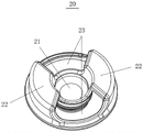
FIG. 3 is a schematic view of a closure according to the present application from above;
FIG. 4 is a schematic view of a closure according to the present application, as seen from below;
FIG. 5 is a schematic structural view of a cap body according to the present application from above;
FIG. 6 is a schematic view of the cap body from below according to the present application;
FIG. 7 is a schematic view of an expanded configuration of a closure and closure body according to the present application;
FIG. 8 is an exploded view of the closure, cap body and tea filter according to the present application;
FIG. 9 is a schematic view of a closure, cap body and tea filter according to the present application after attachment;
FIG. 10 is a schematic cross-sectional view of a lid assembly according to a second embodiment of the present application;
fig. 11 is a schematic cross-sectional view of a lid assembly according to a third embodiment of the present application.
Reference numerals:
10. a cover main body; 11. a liquid outlet; 111. a suction port; 1111. a straw; 112. a straight drinking spout; 12. a cover mounting portion; 121. a tea filter mounting part; 1211. elastic buckle; 1212. supporting the boss; 13. a lid body top wall; 14. a cup rim combining part;
20. sealing the cover; 21. a main body coupling part; 211. a seal ring mounting portion; 22. a liquid outlet sealing part; 23. a yielding groove;
30. filtering the tea; 31. rotating the clasp; 32. flanging; 33. an extension portion;
100. a container body.
Detailed Description
The inventive concept will be described more fully hereinafter with reference to the exemplary embodiments, which however may be embodied in many different forms and should not be construed as limited to the embodiments set forth herein. Rather, these embodiments are provided so that this disclosure will be thorough and complete, and will fully convey the scope of the inventive concept to those skilled in the art.
In the prior art, the cup with double drinking mouths seals or opens the corresponding drinking mouths by configuring the corresponding direct drinking cup cover and the drinking cup cover, but the opening or sealing operation of the cup cover is more complicated when drinking. In addition, the arrangement of a plurality of covers makes the structure of the cup cover extremely complex, which is not beneficial to the manufacturing process.
To address at least one of the above-mentioned problems of the prior art, the present application is directed to a cup lid assembly that is capable of simultaneously opening or simultaneously closing off dual spouts.
The inventive concepts of the present application will be described in detail below with reference to exemplary embodiments.
According to a first aspect of the present application there is provided a lid assembly. As shown in fig. 1 and 2, a cap assembly is used in connection with a container body 100. It should be noted that the container body 100 of the present application can be used for containing liquid, such as, but not limited to, tea, drinking water, beverage, etc., and the temperature of the contained liquid can be determined according to the actual usage situation. Wherein, the bowl cover subassembly includes: lid main part 10 and the closing cap 20 of setting on lid main part 10 are equipped with two at least liquid outlets 11 on the lid main part 10, closing cap 20 include with liquid outlet 11 complex liquid outlet sealing 22, closing cap 20 can rotate for lid main part 10 for two at least liquid outlets 11 open simultaneously or the shutoff simultaneously, thereby conveniently drink.
According to the bowl cover subassembly of this application, when using, only need rotatory closing cap 20 alright expose simultaneously with so that two at least liquid outlets open two at least liquid outlets 11 simultaneously, after using up, along opposite direction rotatory closing cap 20 alright so that two at least liquid outlets are sheltered from by closing cap 20 simultaneously and block two at least liquid outlets 11 simultaneously, open or close easy operation and convenience. In addition, the cup cover assembly is simple in structure and easy to manufacture.
According to the present application, the cap 20 may be completely unscrewed from the cap body 10 (in this case, the cap 20 is separated from the cap body 10), or may be rotated only by a predetermined angle with respect to the cap body 10 (in this case, the cap 20 is not separated from the cap body 10).
In an embodiment, the cap 20 includes a body coupling portion 21 and a liquid outlet sealing portion 22 coupled to the body coupling portion 21, and the body coupling portion 21 is rotatably coupled to the cap body 10 such that the cap 20 can rotate with respect to the cap body 10. The liquid outlet sealing portion 22 protrudes laterally with respect to the outer sidewall of the main body joint portion 21, and the liquid outlet sealing portion 22 is staggered with respect to the at least two liquid outlets 11 so as to be able to open the at least two liquid outlets 11 simultaneously or the liquid outlet sealing portion 22 coincides with the at least two liquid outlets 11 so as to be able to block the at least two liquid outlets 11 simultaneously.
In these embodiments, in the case where at least two liquid outlets 11 need to be opened, the at least two liquid outlets 11 can be opened simultaneously by rotating the body joint portion 21 by a predetermined angle with respect to the cover body 10 so that the liquid outlet sealing portion 22 is misaligned with the at least two liquid outlets 11. Under the condition that at least two liquid outlets 11 need to be plugged, the main body combining part 21 rotates reversely to enable the liquid outlet sealing part 22 to coincide with the at least two liquid outlets 11, so that the at least two liquid outlets 11 can be plugged simultaneously, and the operation mode is simple. The preset angle here may be 20-55.
According to the present application, the liquid outlet sealing portion 22 protrudes laterally with respect to the outer sidewall of the main body combining portion 21, wherein the liquid outlet sealing portion 22 is used for blocking at least two liquid outlets 11. As shown in fig. 2 to 4, the cap 20 includes a body coupling portion 21 and a port sealing portion 22 coupled to the body coupling portion 21, and the port sealing portion 22 may be coupled to an upper end of the body coupling portion 21 and protrude laterally with respect to the upper end of the body coupling portion 21. A sealing gasket is arranged between the liquid outlet sealing part 22 and the corresponding liquid outlet 11, so that the liquid outlet sealing part and the corresponding liquid outlet 11 have better sealing performance when being overlapped and blocked. It should be noted that the application does not limit the position of the liquid outlet sealing portion 22 on the outer side wall of the main body combining portion 21. According to the present application, the port sealing part 22 may be disposed at a plurality of positions on an outer sidewall of the port sealing part 22, for example, but not limited to, the port sealing part 22 may be connected to a lower end of the body coupling part 21 and protrude laterally with respect to the lower end of the body coupling part 21. At this time, the cap mounting portions 12 to be described later may each be formed in a cylindrical structure protruding upward.
In an embodiment, the liquid outlet sealing portions 22 are at least two, a yielding groove 23 is arranged between adjacent liquid outlet sealing portions 22, and under the condition that the liquid outlet sealing portions 22 are staggered with two liquid outlets 11, at least two liquid outlets 11 are respectively exposed at the corresponding yielding groove 23, so that the yielding groove 23 can enable the corresponding liquid outlets 11 to be completely exposed, thereby facilitating the use of at least two liquid outlets 11.
In the embodiment, the liquid outlet 11 includes a drink suction port 111 and a drink through port 112, and the drink suction port 111 and the drink through port 112 are disposed to be staggered in the circumferential direction of the cover main body 10. In a preferred embodiment, the drink-sucking port 111 and the drink-through port 112 are oppositely disposed in the circumferential direction of the cover main body 10, and the liquid outlet sealing portion 22 is provided in at least two corresponding to the drink-sucking port 111 and the drink-through port 112, respectively. In the example shown in fig. 9, a suction pipe 1111 is connected to a lower end of the drinking spout 111, and a convex nozzle (not shown) for facilitating drinking is provided at an upper end of the drinking spout 111.
In these embodiments, by providing the drink suction port 111 and the drink-through port 112 in a staggered manner in the circumferential direction of the lid main body 10, when one of the drink ports is used, the other drink port can function as an air vent, so that the used drink port is smoother when drinking. Through setting up the position of inhaling drinking spout 111 and straight drink mouth 112 relatively, when using one of them drinking spout, another drinking spout is located above the liquid level usually, consequently can ensure not the overflow, has avoided taking place the risk of scalding when splendid attire hot liquid, has guaranteed the security of using. Through setting up two at least liquid outlet sealing 22 and corresponding to inhaling respectively drink mouthful 111 and straight drink mouthful 112, every drink mouthful all has corresponding liquid outlet sealing 22, can guarantee the sealing performance when the shutoff. In addition, during manufacturing, the drinking mouths are not limited to be flush in the height direction, and the manufacturing is convenient.
In an embodiment, as shown in fig. 2, 5 and 6, the cap body 10 includes a cup opening coupling portion 14, a cap mounting portion 12, and a cap body top wall 13 connecting the upper ends of the cup opening coupling portion 14 and the cap mounting portion 12, the cup opening coupling portion 14 and the cap mounting portion 12 are formed in a cylindrical shape, the cap mounting portion 12 is located inside the cup opening coupling portion 14 and is recessed downward with respect to the cap body top wall 13, and an outer side wall of the body coupling portion 21 is screwed or rotatably engaged with an inner side wall of the cap mounting portion 12.
In these embodiments, by providing the cap mounting portion 12 on the cap body 10, the outer side wall of the body coupling portion 21 of the cap 20 is screwed or rotatably engaged with the inner side wall of the cap mounting portion 12 of the cap body 10, whereby the cap 20 can be rotated with respect to the cap body 10, and the structure is simple.
According to the present application, the outer side wall of the body coupling portion 21 of the cap 20 is screwed with the inner side wall of the cap mounting portion 12 of the cap body 10. In an exemplary embodiment, as shown in fig. 7 to 9, the cover main body 10 includes a cover mounting portion 12, wherein the cover mounting portion 12 is recessed downward relative to an upper surface of the cover main body 10, the main body combining portion 21 is also in a recessed structure, the cover mounting portion 12 is sleeved on an outer side of the main body combining portion 21, an outer side wall of the main body combining portion 21 is screwed or rotatably engaged with an inner side wall of the cover mounting portion 12, so that the cover 20 can rotate relative to the cover main body 10. It should be noted that the present application does not limit the cover mounting portion 12 and the body coupling portion 21 to other matching structures, for example, but not limited to, the cover mounting portion 12 and the body coupling portion 21 are respectively protruded upward.
According to the present application, the outer side wall of the body coupling portion 21 of the cover 20 is rotatably engaged with the cover mounting portion 12 of the cover body 10. In an exemplary embodiment, an arc-shaped groove is formed on one of the cover mounting part 12 and the body coupling part 21, and an arc-shaped protrusion is formed on the other of the cover mounting part 12 and the body coupling part 21 such that the cover mounting part 12 and the body coupling part 21 are rotatably engaged, the arc-shaped groove having a length greater than that of the arc-shaped protrusion, and the arc-shaped protrusion is inserted into the arc-shaped groove such that the cover 20 can rotate relative to the cover body 10.
In these embodiments, the cap 20 is able to rotate relative to the cap body 10 by a simple threaded or snap-fit arrangement, making the cap assembly relatively simple to manufacture and use.
In an embodiment, the cap assembly further includes a tea filter 30, a tea filter mounting portion 121 is formed at the bottom of the cap body 10, and the tea filter 30 is detachably coupled to the tea filter mounting portion 121. It should be noted that the tea filter 30 of the present application does not mean that it has only a function of filtering tea, but is a component of the present application for convenience of description, and the tea filter 30 of the present application has a function of filtering various drinks, such as, but not limited to, tea leaves, milk tea, drinks with granules, and the like.
In these embodiments, the tea filter mounting part 121 is formed at the bottom of the cover main body 10, and the tea filter 30 is combined to the tea filter mounting part 121, so that the cup cover assembly with double drinking mouths can have a filtering function at the same time, and is convenient for drinking various beverages. Through setting up tea and straining 30 and tea and strain installation department 121 detachably and combine, can be convenient for use tea to strain or wash tea and strain.
According to the present application, the material of the cap body 10 is plastic, typically selected, for example PP (polypropylene) or PC (polycarbonate). The material of the tea filter may be plastic, glass, ceramic or metal, and the combination position of the tea filter 30 on the cover main body 10 may be slightly different according to different materials in order to obtain convenience of use. The combining position of the cap body 10 and the tea strainer 30 of the present application will be described with reference to a plurality of embodiments, but the combining position of the cap body 10 and the tea strainer 30 is not limited to the embodiments described below, and various combining forms in the prior art may be adopted. Such as, but not limited to, a threaded connection.
A schematic view of the connection structure of the cap main body and the tea strainer according to the first embodiment of the present application is shown in fig. 2. As shown in fig. 2, the tea strainer mounting portion 121 is formed to extend downward from the bottom surface of the cap body 10 in a cylindrical shape, the upper end of the tea strainer 30 is connected to the tea strainer mounting portion 121, an elastic snap 1211 is formed on the tea strainer mounting portion 121, and a rotary catch 31 capable of being rotatably engaged with the elastic snap 1211 is formed on the tea strainer 30.
In these embodiments, the tea filter mounting part 121 formed in a cylindrical shape is extended downward from the bottom surface of the cap body 10, and the tea filter 30 can be detachably coupled to the tea filter mounting part 121 by rotatably engaging the elastic clip 1211 with the rotary catch 31, and the detachment or installation is simple.
According to the present application, the bottom of the cap mounting portion 12 communicates with or is spaced apart from the interior of the tea filter 30. In the case where the bottom of the cap mounting part 12 is spaced apart from the inside of the tea strainer 30, the tea strainer 30 may be directly unscrewed from the cap main body 10, the brew may be placed inside the tea strainer 30, and then the tea strainer 30 may be coupled to the cap main body 10, in which case, although brewing by the liquid may not be directly performed, a beverage having the brew may be obtained by immersing the brew in the liquid. In order to facilitate the use of the tea strainer 30, in the example shown in fig. 2, the lower end of the cap mounting portion 12 has an opening, the tea strainer mounting portion 121 is formed to extend downward along the edge of the opening to form a cylindrical structure, the tea strainer is detachably mounted on the outside of the cylindrical structure, so that the inner cavity of the tea strainer 30 is communicated with the cap mounting portion 12 through the opening, when in use, the cap 20 can be completely screwed off the cap main body 10, at this time, the inside of the tea strainer 30 is exposed outside through the cap mounting portion 12, the brewed object (tea leaves) can be placed conveniently, and the liquid can be poured from the upper end of the cap mounting portion 12 to achieve the function of direct brewing.
In an embodiment, the lower end of the cap mounting portion 12 has an opening, the tea filter mounting portion 121 extends downward from the lower end of the cap mounting portion 12, a supporting boss 1212 protruding inward is formed between the tea filter mounting portion 121 and the cap mounting portion 12, and the upper end of the tea filter 30 is disposed on the upper surface of the supporting boss 1212.
In these embodiments, the lower end of the cover mounting portion 12 has an opening, the tea filter mounting portion 121 is formed by extending downward from the lower end of the cover mounting portion 12, a supporting boss 1212 protruding inward is formed between the tea filter mounting portion 121 and the cover mounting portion 12, and the upper end of the tea filter 30 is disposed on the upper surface of the supporting boss 1212, so that the tea filter 30 made of glass or ceramic material can be more reliably mounted on the supporting boss 1212. In addition, under the condition that the sealing cover 20 is detached, the tea filter 30 can be communicated with the outside through the lower end opening of the sealing cover mounting part 12, so that the tea filter does not need to be taken down when the tea filter is used, and brewing materials can be directly put in from the upper part, so that the times of taking and placing the tea filter 30 are reduced, and the phenomenon that the tea filter falls and is damaged when the tea filter is used can be avoided.
As shown in fig. 5 and 7, a drink spout 111 and a straight drink spout 112 are formed on the lid main body top wall 13, and a tea filter mounting portion 121 is located between the drink spout 111 and the straight drink spout 112.
Fig. 11 is a schematic cross-sectional view of a lid assembly according to a third embodiment of the present application. As shown in fig. 11, the upper end of the tea filter 30 is formed with a flange 32, and the flange 32 is overlapped on the upper surface of the support boss 1212. The bottom surface of the body coupling portion 21 is further formed with a packing mounting portion 211, in which a packing is mounted for sealing between the outer side of the packing mounting portion 211 and the inner wall of the cap mounting portion 12.
FIG. 10 is a schematic cross-sectional view of a lid assembly according to a second embodiment of the present application. As shown in fig. 10, the upper end of the tea filter assembly is further formed with an extension 33 extending upward from the flange 32, the bottom surface of the main body combining portion 21 is further formed with a packing mounting portion 211, and the extension 33 is interposed between the inner side of the cover mounting portion 12 and the outer side of the packing mounting portion 211.
In these embodiments, the drinking spout 111 and the straight drinking spout 112 are formed on the lid main body top wall 13, and since the lid main body top wall 13 is connected to the upper ends of the cup spout coupling portion 14 and the lid mounting portion 12, the drinking spout 111 and the straight drinking spout 112 are relatively located at a high position, and the liquid in the container body 100 can be further prevented from overflowing from the drinking spout.
According to a second aspect of the present application, a container is provided, which includes a container body and the cap assembly in each of the above embodiments, so that all the advantages of each of the above embodiments are achieved, and details are not repeated herein.
In the illustrated embodiment, the container body 100 is connected to the spout engaging portion 14 of the lid body 10 of the cap assembly.
Although the embodiments of the present application have been described in detail above, those skilled in the art may make various modifications and alterations to the embodiments of the present application without departing from the spirit and scope of the present application. It will be understood that those skilled in the art will recognize modifications and variations as falling within the spirit and scope of the embodiments of the application as defined by the claims.
Claims (10)
1. A cup lid assembly, comprising: lid main part (10) and setting are in closing cap (20) on lid main part (10), be equipped with two at least liquid outlets (11) on lid main part (10), closing cap (20) include with liquid outlet (11) complex liquid outlet sealing (22), closing cap (20) can for lid main part (10) are rotatory, make two at least liquid outlets (11) are opened or are the shutoff simultaneously.
2. The cup lid assembly of claim 1, wherein the cover (20) further comprises a body coupling portion (21), the body coupling portion (21) being connected to a liquid outlet sealing portion (22) and rotatably connected to the cover body (10), the liquid outlet sealing portion (22) protruding laterally with respect to an outer side wall of the body coupling portion (21) for blocking the at least two liquid outlets (11); liquid outlet sealing (22) set up to at least two, are equipped with between adjacent liquid outlet sealing (22) and give way groove (23) liquid outlet sealing (22) with under the condition that two liquid outlets (11) stagger, at least two liquid outlets (11) expose through corresponding groove (23) of giving way respectively.
3. The cup cover assembly according to claim 2, wherein the liquid outlet (11) includes a suction port (111) and a direct-drinking port (112), the suction port (111) and the direct-drinking port (112) are provided in a circumferential direction of the cover main body (10), and the liquid outlet sealing portion (22) corresponds to the suction port (111) and the direct-drinking port (112), respectively.
4. The cup lid assembly of claim 3, wherein the lid body (10) includes a cup opening engaging portion (14), a lid mounting portion (12), and a lid body top wall (13) connecting the cup opening engaging portion (14) and an upper end of the lid mounting portion (12), the cup opening engaging portion (14) and the lid mounting portion (12) are both formed in a cylindrical shape, the lid mounting portion (12) is located inside the cup opening engaging portion (14) and is recessed downward with respect to the lid body top wall (13), the body engaging portion (21) is mounted inside the lid mounting portion (12) and is threadedly connected or rotatably engaged with the lid mounting portion (12).
5. The lid assembly of claim 4, further comprising a tea filter (30), the lid body (10) having a bottom formed with a tea filter mounting portion (121), the tea filter (30) being removably coupled to the tea filter mounting portion (121).
6. The cup cover assembly of claim 5, wherein the tea filter mounting portion (121) extends downwards from the bottom surface of the cover main body (10) to form a cylinder, the upper end of the tea filter (30) is connected with the tea filter mounting portion (121), an elastic buckle (1211) is formed on the tea filter mounting portion (121), a rotary catch (31) capable of being rotatably buckled with the elastic buckle (1211) is formed on the tea filter (30), and the bottom of the cover mounting portion (12) is communicated with or separated from the inside of the tea filter (30).
7. The cup cover assembly of claim 5, wherein the lower end of the cover mounting portion (12) is provided with an opening, the tea filter mounting portion (121) extends downward from the lower end of the cover mounting portion (12), an inward protruding supporting boss (1212) is formed between the tea filter mounting portion (121) and the cover mounting portion (12), a flanging (32) is formed at the upper end of the tea filter (30), and the flanging (32) is erected on the upper surface of the supporting boss (1212).
8. The cup cover assembly of claim 7, wherein an extension portion (33) extending upwards from the flanging (32) is further formed at the upper end of the tea filter assembly, a sealing ring mounting portion (211) is further formed at the bottom surface of the main body combining portion (21), and the extension portion (33) is clamped between the inner side of the cover mounting portion (12) and the outer side of the sealing ring mounting portion (211).
9. The cup cover assembly according to claim 6, wherein the drink suction port (111) and a drink-through port (112) are formed on the cover body top wall (13), and the tea filter mounting portion (121) is located between the drink suction port (111) and the drink-through port (112).
10. A container comprising a container body (100) and a lid assembly, characterized in that the lid assembly is as claimed in any one of claims 1 to 9.
Priority Applications (1)
| Application Number | Priority Date | Filing Date | Title |
|---|---|---|---|
| CN202222237827.7U CN218186179U (en) | 2022-08-23 | 2022-08-23 | Cup cover assembly and container |
Applications Claiming Priority (1)
| Application Number | Priority Date | Filing Date | Title |
|---|---|---|---|
| CN202222237827.7U CN218186179U (en) | 2022-08-23 | 2022-08-23 | Cup cover assembly and container |
Publications (1)
| Publication Number | Publication Date |
|---|---|
| CN218186179U true CN218186179U (en) | 2023-01-03 |
Family
ID=84660466
Family Applications (1)
| Application Number | Title | Priority Date | Filing Date |
|---|---|---|---|
| CN202222237827.7U Active CN218186179U (en) | 2022-08-23 | 2022-08-23 | Cup cover assembly and container |
Country Status (1)
| Country | Link |
|---|---|
| CN (1) | CN218186179U (en) |
-
2022
- 2022-08-23 CN CN202222237827.7U patent/CN218186179U/en active Active
Similar Documents
| Publication | Publication Date | Title |
|---|---|---|
| CN111493606A (en) | A half-type tea warehouse and its water cup | |
| CN204931152U (en) | One is made tea thermos cup | |
| EP3967188B1 (en) | Teapot | |
| WO2025077777A1 (en) | Siphon type tea maker | |
| CN222425773U (en) | Cup cover with hidden switch and cup | |
| CA2457244C (en) | Beverage container with one-way valve assembly | |
| CN219183345U (en) | Filtering soaking drinking cup | |
| CN216984426U (en) | Flip coffee cup | |
| CN217959690U (en) | Coffee extraction structure for cap-opening capsule coffee machine | |
| CN213962823U (en) | Water cup | |
| CN214803954U (en) | Direct drinking cup with rotary leakage-proof cover | |
| CN209846786U (en) | Portable sealed direct-drinking coffee cup | |
| CN216984416U (en) | Double-cover tea making cup cover and tea making cup | |
| CN222737651U (en) | Thermos cup that a key was opened | |
| CN209377237U (en) | A kind of filtration teacup | |
| CN209950940U (en) | Inner plugs, container caps and containers | |
| CN212815714U (en) | Water outlet structure of electric heating cup | |
| CN203676746U (en) | Seepage preventing multifunctional cup | |
| CN209915618U (en) | Rotatable cold and hot dual-purpose multifunctional water cup | |
| CN204764769U (en) | Novel bowl cover | |
| CN218246817U (en) | Tea basket of electronic teapot and electronic teapot | |
| CN220655308U (en) | Thermos cup with suction nozzle | |
| CN218484273U (en) | Cup cover and cup | |
| CN208491588U (en) | A filter and drink coffee cup | |
| CN224265567U (en) | Yerba mate teacup with filter straw |
Legal Events
| Date | Code | Title | Description |
|---|---|---|---|
| GR01 | Patent grant | ||
| GR01 | Patent grant |