CN218173865U - Inserted sheet unloading mechanism - Google Patents
Inserted sheet unloading mechanism Download PDFInfo
- Publication number
- CN218173865U CN218173865U CN202221515452.XU CN202221515452U CN218173865U CN 218173865 U CN218173865 U CN 218173865U CN 202221515452 U CN202221515452 U CN 202221515452U CN 218173865 U CN218173865 U CN 218173865U
- Authority
- CN
- China
- Prior art keywords
- plate
- blanking
- insert
- cylinder
- line
- Prior art date
- Legal status (The legal status is an assumption and is not a legal conclusion. Google has not performed a legal analysis and makes no representation as to the accuracy of the status listed.)
- Active
Links
Images


Landscapes
- Re-Forming, After-Treatment, Cutting And Transporting Of Glass Products (AREA)
Abstract
本实用新型公开了一种插片下料机构,涉及工件下料技术领域;包括下料平台、插片X轴运动模组、下料换行运行机构、插片Z轴运动模组以及插片定位机构;下料平台上设置有用于放入玻璃工件的工件料框,插片X轴运动模组设置于下料平台上方,下料换行运行机构设置在插片X轴运动模组上;插片Z轴运动模组设置于下料换行运行机构的前端,并位于工件料框上方,插片定位机构安装在Z轴运动模组上;插片定位机构包括翻转气缸、吸盘安装板以及夹持组件,吸盘安装板连接于翻转气缸上;夹持组件位于翻转气缸的外侧,通过夹持组件对翻转后的玻璃工件进行夹持;本实用新型的有益效果是:能够实现玻璃工件的自动化下料,提高下料效率。
The utility model discloses a piece-inserting blanking mechanism, which relates to the technical field of workpiece blanking; comprising a blanking platform, a piece-inserting X-axis motion module, a material-feeding and line-changing mechanism, a piece-inserting Z-axis movement module, and piece-inserting positioning Mechanism; the blanking platform is provided with a workpiece material frame for placing glass workpieces, the X-axis motion module of the insert is set above the blanking platform, and the blanking and line-changing operating mechanism is set on the X-axis motion module of the insert; The Z-axis motion module is set at the front end of the feeding and changing operation mechanism, and is located above the workpiece material frame. The insertion positioning mechanism is installed on the Z-axis movement module; the insertion positioning mechanism includes a turning cylinder, a suction cup mounting plate and a clamping assembly. , the suction cup mounting plate is connected to the overturning cylinder; the clamping assembly is located on the outside of the overturning cylinder, and the overturned glass workpiece is clamped by the clamping assembly; the beneficial effect of the utility model is that the automatic blanking of the glass workpiece can be realized, Improve cutting efficiency.
Description
技术领域technical field
本实用新型涉及工件下料技术领域,更具体的说,本实用新型涉及一种插片下料机构。The utility model relates to the technical field of workpiece blanking, more specifically, the utility model relates to an insert blanking mechanism.
背景技术Background technique
抛光机也称为研磨机,常常用作机械式研磨、抛光及打蜡。其工作原理是:电动机带动安装在抛光机上的海绵或羊毛抛光盘高速旋转,由于抛光盘和抛光剂共同作用并与待抛表面进行摩擦,进而可达到去除漆面污染、氧化层、浅痕的目的。Polishing machines, also known as grinders, are often used for mechanical grinding, polishing and waxing. Its working principle is: the motor drives the sponge or wool polishing disc installed on the polishing machine to rotate at high speed. Due to the joint action of the polishing disc and the polishing agent and friction with the surface to be polished, it can achieve the effect of removing paint surface pollution, oxide layer and shallow marks. Purpose.
目前市面上均采用精雕机、周抛机等机械设备实现手机的玻璃盖板的加工。加工完成后一般均是人工实现下料,这种下料方式存在以下几个方面的不足:一是加工的玻璃面板较为锐利,易造成工伤事故;二是人工成本逐渐上升,工人难招难以管理,且工人操作机床存在惰性,效率低下。At present, mechanical equipment such as engraving machines and weekly throwing machines are used in the market to process the glass cover of mobile phones. After the processing is completed, the blanking is generally done manually. This blanking method has the following shortcomings: First, the processed glass panel is relatively sharp, which is easy to cause work-related accidents; second, the labor cost is gradually rising, making it difficult to recruit and manage workers. , and the workers operate the machine tool with inertia and low efficiency.
实用新型内容Utility model content
本实用新型的目的在于克服上述技术的不足,提供一种插片下料机构,该插片下料机构能够实现玻璃工件的自动化下料,提高下料效率,相比人工下料更为安全。The purpose of the utility model is to overcome the disadvantages of the above-mentioned technologies, and provide an inserting blanking mechanism, which can realize automatic blanking of glass workpieces, improve blanking efficiency, and is safer than manual blanking.
本实用新型的技术方案是这样实现的:一种插片下料机构,其改进之处在于,包括下料平台、插片X轴运动模组、下料换行运行机构、插片Z轴运动模组以及插片定位机构;The technical solution of the utility model is realized in the following way: a piece-inserting blanking mechanism, its improvement is that it includes a blanking platform, a piece-inserting X-axis motion module, a material-feeding and line-changing operation mechanism, and a piece-plugging Z-axis motion module Group and insert positioning mechanism;
所述下料平台上设置有用于放入玻璃工件的工件料框,插片X轴运动模组设置于下料平台上方,所述下料换行运行机构设置在插片X轴运动模组上,通过插片X轴运动模组的驱动在X轴方向往复运动;The blanking platform is provided with a workpiece material frame for placing glass workpieces, the X-axis motion module of the insert is arranged above the blanking platform, and the line-changing operation mechanism for blanking is arranged on the X-axis motion module of the insert. Driven by the plug-in X-axis movement module to reciprocate in the X-axis direction;
所述插片Z轴运动模组设置于下料换行运行机构的前端,并位于工件料框上方,所述的插片定位机构安装在Z轴运动模组上,通过插片Z轴运动模组的驱动在Z轴方向往复运动;The Z-axis movement module of the insertion piece is arranged at the front end of the blanking and line-changing operation mechanism, and is located above the workpiece material frame. The insertion piece positioning mechanism is installed on the Z-axis movement module, and the Z-axis movement module of the insertion piece The drive reciprocates in the Z-axis direction;
所述的插片定位机构包括翻转气缸、吸盘安装板以及夹持组件,吸盘安装板连接于翻转气缸上,通过吸盘安装板上的吸盘对玻璃工件进行吸附;所述的夹持组件位于翻转气缸的外侧,通过夹持组件对翻转后的玻璃工件进行夹持。The insert positioning mechanism includes a turning cylinder, a suction cup mounting plate and a clamping assembly, the suction cup mounting plate is connected to the turning cylinder, and the glass workpiece is adsorbed by the suction cup on the suction cup mounting plate; the clamping component is located on the turning cylinder The flipped glass workpiece is clamped by the clamping assembly on the outside.
上述的结构中,所述的夹持组件包括框架支撑板、定位气缸、气缸安装板以及滑动连板;In the above structure, the clamping assembly includes a frame support plate, a positioning cylinder, a cylinder mounting plate and a sliding connecting plate;
所述的气缸安装板固定设置在一组框架支撑板的顶端,所述的定位气缸固定在气缸安装板的外侧面,滑动连板滑动安装在气缸安装板的外侧面,且滑动连板与定位气缸的气缸杆相连接;The cylinder mounting plate is fixedly arranged on the top of a group of frame support plates, the positioning cylinder is fixed on the outer surface of the cylinder mounting plate, the sliding connecting plate is slidably installed on the outer surface of the cylinder mounting plate, and the sliding connecting plate and the positioning The cylinder rods of the cylinders are connected;
所述气缸安装板的内侧设置有固定导向板和可调导向板,固定导向板固定安装在气缸安装板上,可调导向板与所述的滑动连板相连接;通过固定导向板和可调导向板实现对玻璃工件的夹持。The inner side of the cylinder mounting plate is provided with a fixed guide plate and an adjustable guide plate, the fixed guide plate is fixedly installed on the cylinder mounting plate, and the adjustable guide plate is connected with the sliding connecting plate; through the fixed guide plate and the adjustable The guide plate realizes the clamping of the glass workpiece.
上述的结构中,所述可调导向板和固定导向板上设置有相对应的导向槽,玻璃工件被夹持在可调导向板和固定导向板的导向槽内。In the above structure, the adjustable guide plate and the fixed guide plate are provided with corresponding guide grooves, and the glass workpiece is clamped in the guide grooves of the adjustable guide plate and the fixed guide plate.
上述的结构中,所述的气缸安装板上设置有定位导轨,所述的滑动连板滑动安装在定位导轨上。In the above structure, the cylinder mounting plate is provided with a positioning guide rail, and the sliding connecting plate is slidably installed on the positioning guide rail.
上述的结构中,所述的可调导向板通过L形的靠角安装板与滑动连板相连接。In the above structure, the adjustable guide plate is connected with the sliding connecting plate through the L-shaped corner mounting plate.
上述的结构中,所述的插片Z轴运动模组包括有沿Z轴方向往复运动的插片RZ滑板,所述的翻转气缸固定在插片RZ滑板的底端,框架支撑板的末端固定在插片RZ滑板上。In the above-mentioned structure, the Z-axis movement module of the insert includes an RZ slide plate that reciprocates along the Z-axis direction, the flipping cylinder is fixed on the bottom end of the RZ slide plate, and the end of the frame support plate is fixed On the insert RZ skateboard.
上述的结构中,所述下料换行运行机构包括推动气缸、换行底板、换行滑轨、换行滑块以及托板;In the above structure, the blanking and changing operation mechanism includes a push cylinder, a changing base plate, a changing slide rail, a changing slider and a supporting plate;
所述的推动气缸固定在换行底板上,两条换行滑轨位于推动气缸的两侧,换行滑块滑动安装在换行滑轨上,所述的托板与换行滑块相固定;The pushing cylinder is fixed on the line-changing base plate, two line-changing slide rails are located on both sides of the pushing cylinder, the line-changing slider is slidably installed on the line-changing slide rails, and the supporting plate is fixed to the line-changing slider;
所述的插片Z轴运动模组与所述的托板固定连接。The Z-axis movement module of the insertion piece is fixedly connected with the support plate.
上述的结构中,所述的下料平台上方还设置有用于驱动工件料框在Y轴方向往复运动的料框驱动模组。In the above structure, a material frame drive module for driving the workpiece material frame to reciprocate in the Y-axis direction is arranged above the material unloading platform.
本实用新型的有益效果是:此种插片下料机构,实现了玻璃工件的自动化下料,全程无需人工参与,提高了下料效率,相比人工下料更为安全。The beneficial effects of the utility model are: the inserting blanking mechanism realizes the automatic blanking of glass workpieces, without manual participation in the whole process, improves the blanking efficiency, and is safer than manual blanking.
附图说明Description of drawings
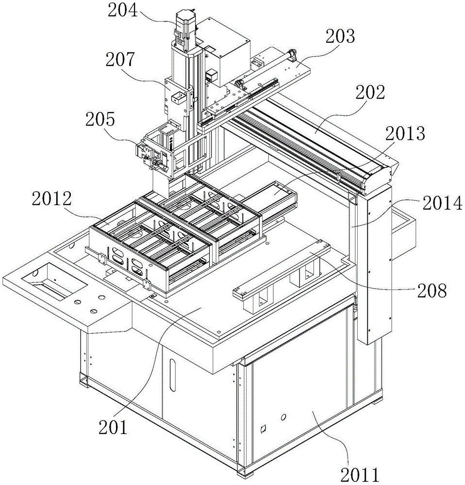
图1为本实用新型的一种插片下料机构的立体结构示意图。Fig. 1 is a three-dimensional structural schematic diagram of an insert blanking mechanism of the present invention.
图2为本实用新型的下料换行运行机构和插片定位机构的结构示意图。Fig. 2 is a structural schematic diagram of the unloading and line-changing running mechanism and the inserting piece positioning mechanism of the utility model.
图3为本实用新型的夹持组件的分解示意图。Fig. 3 is an exploded schematic diagram of the clamping assembly of the present invention.
具体实施方式detailed description
为了使本实用新型的目的、技术方案及优点更加清楚明白,以下结合附图及实施例,对本实用新型进行进一步详细说明。应当理解,此处所描述的具体实施例仅仅用于解释本实用新型,并不用于限定本实用新型。In order to make the purpose, technical solution and advantages of the utility model clearer, the utility model will be further described in detail below in conjunction with the accompanying drawings and embodiments. It should be understood that the specific embodiments described here are only used to explain the utility model, and are not intended to limit the utility model.
参照图1所示,本实用新型公开了一种插片下料机构,通过该插片下料机构,实现玻璃工件的下料,本实施例中,即可实现玻璃盖板的插片式的下料。结合图1所示,该插片下料机构包括下料平台201、插片X轴运动模组202、下料换行运行机构203、插片Z轴运动模组204以及插片定位机构205;下料平台201位于插片底座2011上方,所述下料平台201上设置有用于放入玻璃工件的工件料框2012,工件料框2012的后方还设置有用于驱动工件料框2012在Y轴方向往复运动的料框驱动模组2013。Referring to Figure 1, the utility model discloses an inserting blanking mechanism, through which the blanking of glass workpieces can be realized. In this embodiment, the inserting type of the glass cover plate can be realized. cutting. As shown in FIG. 1 , the insert blanking mechanism includes a
进一步的,下料平台201上设置有竖向的插片X轴支撑架2014,插片X轴运动模组202设置插片X轴支撑架2014的顶端,使插片X轴运动模组202位于下料平台201的上方;所述下料换行运行机构203设置在插片X轴运动模组202上,通过插片X轴运动模组202的驱动在X轴方向往复运动。所述插片Z轴运动模组204设置于下料换行运行机构203的前端,并位于工件料框2012上方,下料换行运行机构203可以对插片Z轴运动模组204在Y轴的方向进行微调。所述的插片定位机构205安装在Z轴运动模组上,通过插片Z轴运动模组的驱动在Z轴方向往复运动。Further, the
上述的实施例中,所述的料框驱动模组2013、插片X轴运动模组202以及插片Z轴运动模组204均采用现有技术中直线电机模组,直线电机模组是基于直线电机以及光栅尺、霍尔传感器、直线导轨等形成的系统集成,可直接引进自动化设备中作为驱动装置。由于其结构在现有技术中非常成熟,因此本实施例中则不再对料框驱动模组2013、插片X轴运动模组202以及插片Z轴运动模组204的结构进行详细的说明。In the above-mentioned embodiment, the material
结合图2所示,对于所述的插片定位机构205,提供了一具体实施例,插片定位机构205包括翻转气缸2051、吸盘安装板2052以及夹持组件2053,吸盘安装板2052连接于翻转气缸2051上,通过吸盘安装板2052上的吸盘对玻璃工件进行吸附;所述的夹持组件2053位于翻转气缸2051的外侧,通过夹持组件2053对翻转后的玻璃工件进行夹持;本实施例中,通过翻转气缸2051将水平状态的玻璃工件翻转至竖直状态。结合图3所示,所述的夹持组件2053包括框架支撑板2054、定位气缸2055、气缸安装板2056以及滑动连板2057;所述的气缸安装板2056固定设置在一组框架支撑板2054的顶端,所述的定位气缸2055通过定位气缸安装板2062固定在气缸安装板2056的外侧面,滑动连板2057滑动安装在气缸安装板2056的外侧面,且滑动连板2057与定位气缸2055的气缸杆相连接,通过定位气缸2055的驱动,带动滑动连板2057进行往复运动。所述气缸安装板2056的内侧设置有固定导向板2058和可调导向板2059,固定导向板2058固定安装在气缸安装板2056上,可调导向板2059与所述的滑动连板2057相连接;通过固定导向板2058和可调导向板2059实现对玻璃工件的夹持。As shown in FIG. 2, a specific embodiment is provided for the
本实施例中,气缸安装板2056上设置有定位导轨2060,所述的滑动连板2057滑动安装在定位导轨2060上;可调导向板2059通过L形的靠角安装板2061与滑动连板2057相连接。通过定位气缸2055的驱动,带动滑动连板2057在定位导轨2060上移动,从而带动可调导向板2059往复运动,调节可调导向板2059与固定导向板2058之间的距离,进而完成对玻璃工件的夹持和松开的操作。可调导向板2059和固定导向板2058上设置有相对应的导向槽,玻璃工件被夹持在可调导向板2059和固定导向板2058的导向槽内。另外,可调导向板2059和固定导向板2058上均设置有腰型孔,通过腰型孔实现可调导向板2059和固定导向板2058的固定,同时也可以对其位置进行调整,从而使固定导向板2058和可调导向板2059适应不同大小的玻璃工件,提高了产品的适用性。In this embodiment, the
上述的实施例中,将可调导向板2059和固定导向板2058,以及驱动部分(包括定位气缸2055、滑动连板2057以及靠角安装板2061)分别设置在气缸安装板2056的内侧面和外侧面,这种设计使夹持组件2053的整体结构更为紧凑;同时,翻转后的玻璃工件被可调导向板2059和固定导向板2058夹持在气缸安装板2056的内侧,气缸安装板2056可以对玻璃工件起到保护作用。In the above-mentioned embodiment, the
结合图2所示,所述的插片Z轴运动模组204包括有沿Z轴方向往复运动的插片RZ滑板207,所述的翻转气缸2051固定在插片RZ滑板207的底端,框架支撑板2054的末端固定在插片RZ滑板207上;通过插片Z轴运动模组204的驱动,带动插片RZ滑板207的上下运动,从而带动翻转气缸2051和夹持组件2053在Z轴方向的往复运动。对于所述的下料换行运行机构203,结合图2所示,本实用新型提供了一具体实施例,所述下料换行运行机构203包括推动气缸2031、换行底板2032、换行滑轨2033、换行滑块2034以及托板2035;所述的推动气缸2031固定在换行底板2032上,两条换行滑轨2033位于推动气缸2031的两侧,换行滑块2034滑动安装在换行滑轨2033上,所述的托板2035与换行滑块2034相固定;所述的插片Z轴运动模组204与所述的托板2035固定连接。通过这种结构,推动气缸2031可以推动托板2035在换行滑轨2033上平移,从而带动插片Z轴运动模组204实现平行。另外,为了提升强度,托板2035上还设置有Z轴支撑板2036,插片Z轴运动模组204与Z轴支撑板2036相固定。As shown in FIG. 2, the insert Z-
结合上述的内容,我们对本实用新型的一种插片下料机构的工作过程进行详细说明,下料平台201上具有与传送带进行对接的传送机构支撑座208,通过传送带将加工完成的玻璃工件传送至下料平台201上方;在插片X轴运动模组202和插片Z轴运动模组204的配合下,吸盘安装板2052上的吸盘对水平状态的玻璃工件进行吸附,吸附完成后插片Z轴运动模组204带动玻璃工件向上运动,此后翻转气缸2051带动玻璃工件翻转至竖直状态;夹持组件2053的可调导向板2059和固定导向板2058对玻璃工件进行夹持。在插片X轴运动模组202和插片Z轴运动模组204驱动下,带动玻璃工件运动至工件料框2012上方,并将玻璃工件插入工件料框2012中,完成插片下料的动作。当工件料框2012中完成一排的玻璃工件下料后,下料换行运行机构203可以驱动插片Z轴运动模组204进行换行,从而实现连续性的插片下料。当其中一个工件料框装满下料的玻璃工件后,料框驱动模组可以驱动工件料框沿Y轴方向平行,在另一个工件料框中进行下料。此种插片下料机构,实现了玻璃工件的自动化下料,全程无需人工参与,提高了下料效率,相比人工下料更为安全。Combining the above-mentioned content, we will describe the working process of a kind of insert blanking mechanism of the utility model in detail. The
以上所描述的仅为本实用新型的较佳实施例,上述具体实施例不是对本实用新型的限制。在本实用新型的技术思想范畴内,可以出现各种变形及修改,凡本领域的普通技术人员根据以上描述所做的润饰、修改或等同替换,均属于本实用新型所保护的范围。The above descriptions are only preferred embodiments of the present utility model, and the above specific embodiments do not limit the present utility model. Within the scope of the technical ideas of the present utility model, various deformations and modifications can occur, and any retouching, modification or equivalent replacement made by those skilled in the art according to the above descriptions all belong to the protection scope of the present utility model.
Claims (8)
Priority Applications (1)
| Application Number | Priority Date | Filing Date | Title |
|---|---|---|---|
| CN202221515452.XU CN218173865U (en) | 2022-06-16 | 2022-06-16 | Inserted sheet unloading mechanism |
Applications Claiming Priority (1)
| Application Number | Priority Date | Filing Date | Title |
|---|---|---|---|
| CN202221515452.XU CN218173865U (en) | 2022-06-16 | 2022-06-16 | Inserted sheet unloading mechanism |
Publications (1)
| Publication Number | Publication Date |
|---|---|
| CN218173865U true CN218173865U (en) | 2022-12-30 |
Family
ID=84609109
Family Applications (1)
| Application Number | Title | Priority Date | Filing Date |
|---|---|---|---|
| CN202221515452.XU Active CN218173865U (en) | 2022-06-16 | 2022-06-16 | Inserted sheet unloading mechanism |
Country Status (1)
| Country | Link |
|---|---|
| CN (1) | CN218173865U (en) |
Cited By (1)
| Publication number | Priority date | Publication date | Assignee | Title |
|---|---|---|---|---|
| CN117104880A (en) * | 2023-10-13 | 2023-11-24 | 深圳铭创智能装备有限公司 | Realize full-automatic inserted sheet equipment |
-
2022
- 2022-06-16 CN CN202221515452.XU patent/CN218173865U/en active Active
Cited By (2)
| Publication number | Priority date | Publication date | Assignee | Title |
|---|---|---|---|---|
| CN117104880A (en) * | 2023-10-13 | 2023-11-24 | 深圳铭创智能装备有限公司 | Realize full-automatic inserted sheet equipment |
| CN117104880B (en) * | 2023-10-13 | 2024-04-12 | 深圳铭创智能装备有限公司 | Realize full-automatic inserted sheet equipment |
Similar Documents
| Publication | Publication Date | Title |
|---|---|---|
| CN104191886A (en) | Double-faced carving machine for wooden door leaf | |
| CN102390212A (en) | Four-shaft linkage multi-head three-dimensional sculpturing machine | |
| CN219470403U (en) | XY axle automatic positioning sewing mechanism | |
| CN216800737U (en) | Wiping mechanism | |
| CN115026694A (en) | Efficient full-automatic polishing machine | |
| CN114770263A (en) | Efficient automatic polishing machine device | |
| CN214559821U (en) | Large-size belt brush polishing device | |
| CN210478250U (en) | A non-stop loading and unloading mechanism of CNC engraving machine for sheet metal | |
| CN212886009U (en) | Servo clamping machine | |
| CN114654369A (en) | Full-automatic polishing equipment | |
| CN211681322U (en) | Metal sheet welding seam levels device for machining | |
| CN205889935U (en) | A mobile phone case forming and processing integrated machine | |
| CN113084637A (en) | Sample block edge grinding machine | |
| CN219053122U (en) | Multifunctional plate chamfering machine | |
| CN202462145U (en) | Container corner post beveling and chamfering machine | |
| CN211638089U (en) | A rolling water neck equipment for thermal insulation cup processing | |
| CN212218097U (en) | Polishing device applied to robot | |
| CN206484384U (en) | A kind of automatic sander | |
| CN217800677U (en) | High-efficient automatic burnishing machine device | |
| CN210208830U (en) | Plate shearing machine | |
| CN210756977U (en) | Full-automatic plane grinding device | |
| CN211334269U (en) | Pre-processing device for foaming pre-embedded connecting piece | |
| CN115910903A (en) | Pickup device for a quartz wafer nozzle | |
| CN215881053U (en) | Platform horizontal migration formula corner welding seam angle grinder | |
| CN224182750U (en) | An expansion valve grinding machine |
Legal Events
| Date | Code | Title | Description |
|---|---|---|---|
| GR01 | Patent grant | ||
| GR01 | Patent grant | ||
| TR01 | Transfer of patent right | ||
| TR01 | Transfer of patent right |
Effective date of registration: 20250831 Address after: Room 501-2432, Office Building, Development Zone, No. 8, Xingsheng South Road, Economic Development Zone, Miyun District, Beijing 101500 (Central Office Area of Economic Development Zone) Patentee after: Beijing Abacus Industrial Technology Co.,Ltd. Country or region after: China Address before: 337000 lijialang formation, Guanli village, Laoguan Town, Xiangdong District, Pingxiang City, Jiangxi Province Patentee before: Jiangxi Ruimei Machinery Equipment Co.,Ltd. Country or region before: China |
|
| TR01 | Transfer of patent right | ||
| TR01 | Transfer of patent right |
Effective date of registration: 20250924 Address after: 518000 Guangdong Province Shenzhen City Nanshan District Yuehai Street Haizhu Community Houpengbin Road 3368 Pengrenda Business Plaza 3217 Patentee after: Guangdong Tantai New Material Technology Co.,Ltd. Country or region after: China Patentee after: Zhejiang Tantainxing Material Technology Co.,Ltd. Address before: Room 501-2432, Office Building, Development Zone, No. 8, Xingsheng South Road, Economic Development Zone, Miyun District, Beijing 101500 (Central Office Area of Economic Development Zone) Patentee before: Beijing Abacus Industrial Technology Co.,Ltd. Country or region before: China |