CN218168770U - A drilling device for steel belly honing - Google Patents
A drilling device for steel belly honing Download PDFInfo
- Publication number
- CN218168770U CN218168770U CN202221801608.0U CN202221801608U CN218168770U CN 218168770 U CN218168770 U CN 218168770U CN 202221801608 U CN202221801608 U CN 202221801608U CN 218168770 U CN218168770 U CN 218168770U
- Authority
- CN
- China
- Prior art keywords
- steel
- honing
- plate
- sliding
- type
- Prior art date
- Legal status (The legal status is an assumption and is not a legal conclusion. Google has not performed a legal analysis and makes no representation as to the accuracy of the status listed.)
- Expired - Fee Related
Links
- 229910000831 Steel Inorganic materials 0.000 title claims abstract description 69
- 239000010959 steel Substances 0.000 title claims abstract description 69
- 210000001015 abdomen Anatomy 0.000 title claims abstract description 43
- 238000005553 drilling Methods 0.000 title claims description 12
- 238000004080 punching Methods 0.000 claims abstract description 50
- 230000007246 mechanism Effects 0.000 claims abstract description 36
- 230000003014 reinforcing effect Effects 0.000 claims description 11
- 238000000926 separation method Methods 0.000 claims description 10
- 206010066054 Dysmorphism Diseases 0.000 claims 2
- 230000002787 reinforcement Effects 0.000 description 12
- 230000000694 effects Effects 0.000 description 8
- 230000009286 beneficial effect Effects 0.000 description 7
- 238000005457 optimization Methods 0.000 description 7
- 238000010276 construction Methods 0.000 description 5
- 238000010586 diagram Methods 0.000 description 3
- 230000007774 longterm Effects 0.000 description 3
- 238000005259 measurement Methods 0.000 description 3
- 239000002131 composite material Substances 0.000 description 2
- 238000006073 displacement reaction Methods 0.000 description 2
- 230000003187 abdominal effect Effects 0.000 description 1
- 230000013011 mating Effects 0.000 description 1
- 238000000034 method Methods 0.000 description 1
- 238000012986 modification Methods 0.000 description 1
- 230000004048 modification Effects 0.000 description 1
- 238000003825 pressing Methods 0.000 description 1
- 239000002436 steel type Substances 0.000 description 1
- 210000002435 tendon Anatomy 0.000 description 1
Images


Landscapes
- Working Measures On Existing Buildindgs (AREA)
Abstract
Description
技术领域technical field
本实用新型涉及钢珩腹打孔技术领域,特别涉及一种用于钢珩腹的打孔装置。The utility model relates to the technical field of steel honking punching, in particular to a punching device for steel honking.
背景技术Background technique
钢桁腹是在一种运用在混凝土组合梁桥的一种新型组合结构桥梁,在构造上采用桁式钢腹杆代替混凝土箱梁中的混凝土腹板,将腹杆端部节点直接嵌固在混凝土翼板中,形成由混凝土顶板、桁腹钢杆、混凝土底板、体外和体内预应力钢束共同工作的组合结构体系,在对钢桁腹与各部组件进行安装连接时需要在钢桁腹的表面开设孔槽,大部分都需要工作人员手持打孔的装置进行打孔,其不利于长时间进行作业,且打孔的位置以及孔与孔之间的间距得不到保障,影响施工效率,还加大工作人员的劳动强度,间接增加了经济损失。The steel truss web is a new type of composite structure bridge used in concrete composite girder bridges. In terms of structure, truss-type steel webs are used to replace the concrete webs in the concrete box girder, and the end nodes of the webs are directly embedded in the In the concrete wing slab, a combined structural system consisting of the concrete roof, truss web steel rods, concrete bottom slab, external and internal prestressed steel tendons is formed. When installing and connecting the steel truss web and various components, it is necessary to Hole slots are set on the surface, and most of them require the staff to hold the punching device to punch holes, which is not conducive to long-term operation, and the position of the holes and the distance between the holes cannot be guaranteed, which affects the construction efficiency. Also increase the labor intensity of staff, indirectly increased economic losses.
实用新型内容Utility model content
本实用新型提供一种用于钢珩腹的打孔装置,旨在解决现有的在对钢桁腹与各部组件进行安装连接时需要在钢桁腹的表面开设孔槽,大部分都需要工作人员手持打孔的装置进行打孔,其操作起来不够便捷,且打孔的位置以及孔与孔之间的间距得不到保障,影响施工效率,还加大工作人员的劳动强度,间接增加了经济损失的问题。The utility model provides a punching device for steel truss, which aims to solve the problem that holes need to be opened on the surface of the steel truss when installing and connecting the steel truss and various components, most of which require work. Personnel hold the punching device to punch holes, which is not convenient to operate, and the position of the punching hole and the distance between the holes cannot be guaranteed, which affects the construction efficiency and increases the labor intensity of the staff, which indirectly increases The question of economic loss.
本实用新型是这样实现的,一种用于钢珩腹的打孔装置,包括钢珩腹本体,所述钢珩腹本体两侧的内壁均设置有升降式多位辅滑机构,所述钢珩腹本体的表面套设有与升降式多位辅滑机构配合使用的N型架,所述N型架的顶部开设有第一滑槽,所述N型架顶部的两侧均固定连接有立块,两个立块相对的一侧之间固定连接有滑杆,所述滑杆的表面设置有滑动升降式打孔机构;The utility model is achieved in this way. A punching device for steel belly honking includes a steel belly honking body. The inner walls of both sides of the steel The surface of the belly honking body is covered with an N-shaped frame used in conjunction with the lifting multi-position auxiliary sliding mechanism. The top of the N-shaped frame is provided with a first chute, and both sides of the top of the N-shaped frame are fixedly connected with A vertical block, a sliding bar is fixedly connected between the opposite sides of the two vertical blocks, and the surface of the sliding bar is provided with a sliding lifting type punching mechanism;
所述滑动升降式打孔机构包括滑动框、拉动式制动卡件、液压缸、连接板和电动钻孔组件,所述滑动框滑动连接在滑杆的表面,所述拉动式制动卡件滑动连接在滑动框的内壁,所述液压缸固定连接在滑动框的底部,所述液压缸伸缩端穿过第一滑槽固定连接在连接板的顶部,所述电动钻孔组件固定连接在连接板的底部。The sliding lifting type punching mechanism includes a sliding frame, a pulling type brake clip, a hydraulic cylinder, a connecting plate and an electric drilling assembly, the sliding frame is slidably connected to the surface of the slide bar, and the pulling type braking clip Slidingly connected to the inner wall of the sliding frame, the hydraulic cylinder is fixedly connected to the bottom of the sliding frame, the telescopic end of the hydraulic cylinder is fixedly connected to the top of the connecting plate through the first chute, and the electric drilling assembly is fixedly connected to the connecting plate bottom of the board.
为了达到可以进行滑动的效果,作为本实用新型的一种用于钢珩腹的打孔装置优选的,所述升降式多位辅滑机构包括顶板、加固板、轴式滑轮、伸缩杆、底板和一体式滑轮,所述轴式滑轮的数量为若干个,所述伸缩杆的数量为四个,所述一体式滑轮的数量为若干个,所述顶板靠近N型架内壁的一侧与N型架的内壁固定连接,,所述加固板固定连接在顶板的顶部,所述轴式滑轮活动连接在加固板的顶部,所述伸缩杆固定连接在顶板的底部,所述底板固定连接在伸缩杆的底部,所述一体式滑轮转动连接在底板底部的内壁。In order to achieve the effect of being able to slide, as a kind of punching device for steel belly honing of the utility model, the lifting type multi-position auxiliary sliding mechanism includes a top plate, a reinforcement plate, a shaft pulley, a telescopic rod, and a bottom plate. and one-piece pulleys, the number of the shaft pulleys is several, the number of the telescopic rods is four, the number of the one-piece pulleys is several, and the side of the top plate close to the inner wall of the N-shaped frame is connected to the N The inner wall of the molded frame is fixedly connected, the reinforcing plate is fixedly connected to the top of the top plate, the shaft pulley is movably connected to the top of the reinforcing plate, the telescopic rod is fixedly connected to the bottom of the top plate, and the bottom plate is fixedly connected to the telescopic The bottom of the rod, and the integrated pulley is rotatably connected to the inner wall of the bottom of the bottom plate.
为了达到对轴式滑轮进行加固的效果,作为本实用新型的一种用于钢珩腹的打孔装置优选的,所述轴式滑轮的表面活动连接有加固套,所述加固套靠近加固板的一侧与加固板固定连接。In order to achieve the effect of reinforcing the shaft pulley, as a punching device for steel belly honing of the utility model, the surface of the shaft pulley is movably connected with a reinforcement sleeve, and the reinforcement sleeve is close to the reinforcement plate One side is fixedly connected with the reinforcing plate.
为了达到辅助滑动和针对不同的钢型进行移动的效果,作为本实用新型的一种用于钢珩腹的打孔装置优选的,两个顶板和两个底板相对的一侧之间均开设有凹槽,所述凹槽远离N型架相对的一侧之间固定连接有伸缩式滑轮,所述伸缩式滑轮的数量为若干个。In order to achieve the effect of assisting sliding and moving for different steel types, as a kind of punching device for steel belly honing of the utility model, it is preferable that there are holes between the opposite sides of the two top plates and the two bottom plates. Groove, telescopic pulleys are fixedly connected between the opposite sides of the groove away from the N-shaped frame, and the number of the telescopic pulleys is several.
为了达到测量横向需打孔距离的效果,作为本实用新型的一种用于钢珩腹的打孔装置优选的,所述N型架的前侧固定连接有横向距离测量板,所述横向距离测量板的底部滑动连接有定位板。In order to achieve the effect of measuring the distance to be punched in the horizontal direction, as a kind of punching device for steel honing of the utility model, the front side of the N-shaped frame is fixedly connected with a lateral distance measuring plate, and the lateral distance The bottom of the measurement board is slidingly connected with a positioning board.
为了达到纵向移动测量并定位打孔的效果,作为本实用新型的一种用于钢珩腹的打孔装置优选的,所述N型架的两侧均开设有T型槽,所述T型槽的内壁滑动连接有T型块,所述T型块远离T型槽的一侧固定连接有纵向测距杆,两个纵向测距杆相对的一侧之间固定连接有横杆,所述横杆的顶部开设有第二滑槽,所述第二滑槽的内壁设置有辅助标点组件。In order to achieve the effect of longitudinal movement measurement and positioning punching, as a kind of punching device for steel belly honning of the utility model, it is preferred that both sides of the N-shaped frame are provided with T-shaped grooves, and the T-shaped The inner wall of the slot is slidingly connected with a T-shaped block, and the side of the T-shaped block away from the T-shaped slot is fixedly connected with a longitudinal distance measuring rod, and a horizontal bar is fixedly connected between the opposite sides of the two longitudinal distance measuring rods. The top of the cross bar is provided with a second chute, and the inner wall of the second chute is provided with an auxiliary punctuation assembly.
为了达到对需要打孔位置进行标点定位的效果,作为本实用新型的一种用于钢珩腹的打孔装置优选的,所述辅助标点组件包括套杆、连接杆、弹簧、固定盘、标点笔,所述套杆活动连接在横杆的顶部,所述连接杆滑动连接在套杆的内壁,所述弹簧设置在连接杆的外侧,所述固定盘固定连接在连接杆外侧的底部,所述标点笔固定连接在连接杆的底部。In order to achieve the effect of punctuating the positions that need to be punched, as a kind of punching device for steel belly honing of the utility model, the auxiliary punctuating assembly includes a sleeve rod, a connecting rod, a spring, a fixed plate, a punctuating point pen, the sleeve rod is movably connected to the top of the cross bar, the connecting rod is slidably connected to the inner wall of the sleeve rod, the spring is arranged on the outside of the connecting rod, and the fixed plate is fixedly connected to the bottom of the outside of the connecting rod. The punctuation pen is fixedly connected to the bottom of the connecting rod.
为了达到升降式多位辅滑机构和辅助标点组件配合使用的效果,作为本实用新型的一种用于钢珩腹的打孔装置优选的,所述连接杆底部的外侧固定连接有配合板,所述配合板的底部活动连接有分离板,所述配合板和分离板的顶部均开设有异形槽,所述异形槽的内壁设置有异形扭杆,所述分离板远离配合板的一侧固定连接在连接板的后侧。In order to achieve the effect of the combined use of the lifting type multi-position auxiliary sliding mechanism and the auxiliary punctuation assembly, as a kind of punching device for steel belly honing of the utility model, it is preferred that the outer side of the bottom of the connecting rod is fixedly connected with a matching plate, The bottom of the matching plate is movably connected with a separation plate, and the tops of the matching plate and the separation plate are provided with special-shaped grooves, and the inner wall of the special-shaped groove is provided with a special-shaped torsion bar, and the side of the separation plate away from the matching plate is fixed. Connected on the rear side of the connecting plate.
与现有技术相比,本实用新型的有益效果是:Compared with the prior art, the beneficial effects of the utility model are:
该用于钢珩腹的打孔装置,通过设置升降式多位辅滑机构、N型架和滑动升降式打孔机构,在对钢珩腹本体与各部组件进行安装连接时需要在钢珩腹本体的表面开设孔槽,将整体升降式多位辅滑机构置于需要打孔的钢珩腹本体的内壁,根据钢珩腹本体的大小以及宽度,经过伸缩杆对顶板和底板进行一个支撑,使得顶板会向上移动并将顶部的轴式滑轮一并向上推动,使得轴式滑轮抵至钢珩腹本体内壁的顶部,然后轴式滑轮和底板底部的一体式滑轮作业时可同时进行移动,利于在打孔时配合N型架进行位移,对其它位置进行打孔,再经过滑杆外侧的滑动框可左右横向可进行调节,移动完成后利用拉动式制动卡件对滑动框进行固定,液压缸伸缩端穿过其第一滑槽对连接板进行推动并带动运行电动钻孔组件对钢珩腹本体进行打孔,利于长时间进行作业,且打孔的位置以及打孔的间距得到保障,增加施工效率,降低工作人员的劳动强度,间接避免了经济损失。The punching device for steel belly honing needs to install and connect the steel belly honing body and various components by setting up and down multi-position auxiliary sliding mechanism, N-shaped frame and sliding lifting type punching mechanism. Hole slots are set on the surface of the main body, and the integral lifting multi-position auxiliary sliding mechanism is placed on the inner wall of the steel belly honing body that needs to be punched. According to the size and width of the steel belly honing body, the top plate and the bottom plate are supported by telescopic rods. The top plate will move upwards and the shaft pulleys on the top will be pushed up together, so that the shaft pulleys will reach the top of the inner wall of the steel honning body, and then the shaft pulleys and the integrated pulley at the bottom of the bottom plate can move simultaneously during operation, which is beneficial When punching, cooperate with the N-shaped frame to move, and punch other positions, and then the sliding frame on the outside of the slider can be adjusted left and right. The telescopic end of the cylinder pushes the connecting plate through its first chute and drives the electric drilling assembly to punch holes in the steel belly honing body, which is beneficial to long-term operations, and the location and spacing of the holes are guaranteed. Increase construction efficiency, reduce labor intensity of staff, and indirectly avoid economic losses.
附图说明Description of drawings
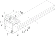
图1为本实用新型的用于钢珩腹的打孔装置的整体结构图;Fig. 1 is the overall structural diagram of the punching device that is used for steel belly honing of the present utility model;
图2为本实用新型中升降式多位辅滑机构的结构示意图;Fig. 2 is the structure schematic diagram of lifting type multi-position auxiliary sliding mechanism in the utility model;
图3为本实用新型中N型架的结构示意图;Fig. 3 is the structural representation of N type frame among the utility model;
图4为本实用新型中滑动升降式打孔机构的结构示意图;Fig. 4 is the structural representation of sliding lift type punching mechanism in the utility model;
图5为本实用新型中辅助标点组件的结构示意图。Fig. 5 is a structural schematic diagram of the auxiliary punctuation component in the utility model.
图中,1、钢珩腹本体;2、升降式多位辅滑机构;201、顶板;202、加固板;203、轴式滑轮;204、伸缩杆;205、底板;206、一体式滑轮;3、N型架;4、第一滑槽;5、立块;6、滑杆;7、滑动升降式打孔机构;701、滑动框;702、拉动式制动卡件;703、液压缸;704、连接板;705、电动钻孔组件;8、加固套;9、凹槽;10、伸缩式滑轮;11、横向距离测量板;12、定位板;13、T型槽;14、T型块;15、纵向测距杆;16、横杆;17、第二滑槽;18、辅助标点组件;1801、套杆;1802、连接杆;1803、弹簧;1804、固定盘;1805、标点笔;19、配合板;20、分离板;21、异形槽;22、异形扭杆。In the figure, 1. Steel belly honing body; 2. Lifting multi-position auxiliary sliding mechanism; 201, top plate; 202, reinforcement plate; 203, shaft pulley; 204, telescopic rod; 205, bottom plate; 206, integrated pulley; 3. N-shaped frame; 4. The first chute; 5. Upright block; 6. Slide bar; 7. Sliding lifting punching mechanism; 701. Sliding frame; 702. Pulling brake clip; 703. Hydraulic cylinder ; 704, connection plate; 705, electric drilling assembly; 8, reinforcement sleeve; 9, groove; 10, telescopic pulley; 11, lateral distance measuring plate; 12, positioning plate; Type block; 15, longitudinal distance measuring rod; 16, cross bar; 17, second chute; 18, auxiliary punctuation assembly; 1801, sleeve rod; 1802, connecting rod; 1803, spring; 1804, fixed plate; Pen; 19, matching plate; 20, separation plate; 21, special-shaped groove; 22, special-shaped torsion bar.
具体实施方式detailed description
为了使本实用新型的目的、技术方案及优点更加清楚明白,以下结合附图及实施例,对本实用新型进行进一步详细说明。应当理解,此处所描述的具体实施例仅仅用以解释本实用新型,并不用于限定本实用新型。In order to make the purpose, technical solution and advantages of the utility model clearer, the utility model will be further described in detail below in conjunction with the accompanying drawings and embodiments. It should be understood that the specific embodiments described here are only used to explain the utility model, and are not intended to limit the utility model.
在本实用新型的描述中,需要理解的是,术语“长度”、“宽度”、“上”、“下”、“前”、“后”、“左”、“右”、“竖直”、“水平”、“顶”、“底”“内”、“外”等指示的方位或位置关系为基于附图所示的方位或位置关系,仅是为了便于描述本实用新型和简化描述,而不是指示或暗示所指的装置或元件必须具有特定的方位、以特定的方位构造和操作,因此不能理解为对本实用新型的限制。此外,在本实用新型的描述中,“多个”的含义是两个或两个以上,除非另有明确具体的限定。In describing the present invention, it should be understood that the terms "length", "width", "upper", "lower", "front", "rear", "left", "right", "vertical" , "horizontal", "top", "bottom", "inner", "outer" and other indicated orientations or positional relationships are based on the orientations or positional relationships shown in the drawings, and are only for the convenience of describing the utility model and simplifying the description. It does not indicate or imply that the device or element referred to must have a specific orientation, be constructed and operate in a specific orientation, and therefore should not be construed as limiting the present invention. In addition, in the description of the present utility model, "plurality" means two or more, unless otherwise specifically defined.
请参阅图1-5,本实用新型提供技术方案:一种用于钢珩腹的打孔装置,包括钢珩腹本体1,钢珩腹本体1两侧的内壁均设置有升降式多位辅滑机构2,钢珩腹本体1的表面套设有与升降式多位辅滑机构2配合使用的N型架3,N型架3的顶部开设有第一滑槽4,N型架3顶部的两侧均固定连接有立块5,两个立块5相对的一侧之间固定连接有滑杆6,滑杆6的表面设置有滑动升降式打孔机构7;Please refer to Figures 1-5, the utility model provides a technical solution: a punching device for steel belly honing, including a steel belly honing body 1, and the inner walls of both sides of the steel belly honing body 1 are equipped with lifting multi-position
滑动升降式打孔机构7包括滑动框701、拉动式制动卡件702、液压缸703、连接板704和电动钻孔组件705,滑动框701滑动连接在滑杆6的表面,拉动式制动卡件702滑动连接在滑动框701的内壁,液压缸703固定连接在滑动框701的底部,液压缸703伸缩端穿过第一滑槽4固定连接在连接板704的顶部,电动钻孔组件705固定连接在连接板704的底部。The sliding lifting
在本实施例中:通过设置升降式多位辅滑机构2、N型架3和滑动升降式打孔机构7,在对钢珩腹本体1与各部组件进行安装连接时需要在钢珩腹本体1的表面开设孔槽,将整体升降式多位辅滑机构2置于需要打孔的钢珩腹本体1的内壁,根据钢珩腹本体1的大小以及宽度,经过伸缩杆204对顶板201和底板205进行一个支撑,使得顶板201会向上移动并将顶部的轴式滑轮203一并向上推动,使得轴式滑轮203抵至钢珩腹本体1内壁的顶部,然后轴式滑轮203和底板205底部的一体式滑轮206作业时可同时进行移动,利于在打孔时配合N型架3进行位移,对其它位置进行打孔,再经过滑杆6外侧的滑动框701可左右横向可进行调节,移动完成后利用拉动式制动卡件702对滑动框701进行固定,液压缸703伸缩端穿过其第一滑槽4对连接板704进行推动并带动运行电动钻孔组件705对钢珩腹本体1进行打孔,利于长时间进行作业,且打孔的位置以及打孔的间距得到保障,增加施工效率,降低工作人员的劳动强度,间接避免了经济损失。In this embodiment: by setting up and down multi-position
作为本实用新型的技术优化方案,升降式多位辅滑机构2包括顶板201、加固板202、轴式滑轮203、伸缩杆204、底板205和一体式滑轮206,轴式滑轮203的数量为若干个,伸缩杆204的数量为四个,一体式滑轮206的数量为若干个,顶板201靠近N型架3内壁的一侧与N型架3的内壁固定连接,加固板202固定连接在顶板201的顶部,轴式滑轮203活动连接在加固板202的顶部,伸缩杆204固定连接在顶板201的底部,底板205固定连接在伸缩杆204的底部,一体式滑轮206转动连接在底板205底部的内壁。As a technical optimization scheme of the present utility model, the lifting type multi-position
在本实施例中:在使用时,将整体升降式多位辅滑机构2搁置在需要进行打孔的钢珩腹本体1的内壁,根据钢珩腹本体1的大小以及宽度经过伸缩杆204对顶板201和底板205进行一个支撑,使得顶板201会向上移动并将顶部的轴式滑轮203一并向上推动,使得轴式滑轮203抵至钢珩腹本体1内壁的顶部,然后轴式滑轮203和底板205底部的一体式滑轮206作业时可同时进行移动,使得在打孔时配合N型架3可做得到移动位移,便于使用。In this embodiment: when in use, the integral lifting type multi-position
作为本实用新型的技术优化方案,轴式滑轮203的表面活动连接有加固套8,加固套8靠近加固板202的一侧与加固板202固定连接。As a technical optimization scheme of the present invention, the surface of the shaft pulley 203 is movably connected with a
在本实施例中:通过设置加固套8,提升对轴式滑轮203定位效果并对其限位在加固板202的顶部,避免在作业时出现脱落的现象。In this embodiment: by setting the reinforcing
作为本实用新型的技术优化方案,两个顶板201和两个底板205相对的一侧之间均开设有凹槽9,凹槽9远离N型架3相对的一侧之间固定连接有伸缩式滑轮10,伸缩式滑轮10的数量为若干个。As a technical optimization scheme of the present utility model, a groove 9 is provided between the opposite sides of the two
在本实施例中:通过设置凹槽9,使得伸缩式滑轮10可以安装在其的内壁,通过设置伸缩式滑轮10,可辅助升降式多位辅滑机构2进行移动,多个伸缩式滑轮10更能增加整体的稳定性。In this embodiment: by setting the groove 9, the telescopic pulley 10 can be installed on its inner wall; It can also increase the overall stability.
作为本实用新型的技术优化方案,N型架3的前侧固定连接有横向距离测量板11,横向距离测量板11的底部滑动连接有定位板12。As a technical optimization scheme of the present invention, the front side of the N-shaped
在本实施例中:通过设置横向距离测量板11和定位板12,提前进行对需要打孔位置的距离进行测量并进行定位引导,便于滑动升降式打孔机构7在打孔时可以直接进行作业。In this embodiment: by setting the horizontal
作为本实用新型的技术优化方案,N型架3的两侧均开设有T型槽13,T型槽13的内壁滑动连接有T型块14,T型块14远离T型槽13的一侧固定连接有纵向测距杆15,两个纵向测距杆15相对的一侧之间固定连接有横杆16,横杆16的顶部开设有第二滑槽17,第二滑槽17的内壁设置有辅助标点组件18。As a technical optimization scheme of the present utility model, both sides of the N-shaped
在本实施例中:通过设置T型槽13、T型块14、纵向测距杆15、横杆16和第二凹槽9,T型块14配合T型槽13可在其内部进行滑动,再加上T型块14外侧的纵向测距杆15可以实现移动进行对距离的测量,使得位于纵向测距杆15之间的横杆16加设第二滑槽17可以衬托辅助标点组件18在对距离进行测量完成后可以直接标号,利于作业的使用。In this embodiment: by setting the T-shaped
作为本实用新型的技术优化方案,辅助标点组件18包括套杆1801、连接杆1802、弹簧1803、固定盘1804和标点笔1805,套杆1801活动连接在横杆16的顶部,连接杆1802滑动连接在套杆1801的内壁,弹簧1803设置在连接杆1802的外侧,固定盘1804固定连接在连接杆1802外侧的底部,标点笔1805固定连接在连接杆1802的底部。As a technical optimization scheme of the present utility model, the
在本实施例中:通过设置套杆1801、连接杆1802、弹簧1803、固定盘1804和标点笔1805,在使用时按压套杆1801顶部的连接杆1802,因连接杆1802设计的原因,其顶部的压力会对外侧的弹簧1803进行压缩的作用,使得连接杆1802推动底部的标点笔1805对钢珩腹本体1的顶部进行标记,完成后在不按压的情况下各部件会全部归位,这时位于连接杆1802底部的固定盘1804会对连接杆1802进行限位的作用,防止其脱离第二滑槽17。In this embodiment: by setting the
作为本实用新型的技术优化方案,连接杆1802底部的外侧固定连接有配合板19,配合板19的底部活动连接有分离板20,配合板19和分离板20的顶部均开设有异形槽21,异形槽21的内壁设置有异形扭杆22,分离板20远离配合板19的一侧固定连接在连接板704的后侧。As a technical optimization scheme of the present utility model, the outer side of the bottom of the connecting
在本实施例中:通过设置配合板19、分离板20、异形槽21和异形扭杆22,利用配合板19和分离板20两者分别连接在连接杆1802和连接板704的外侧,再使异形扭杆22穿过两者顶部的异形槽21进行扭动连接,相当于滑动升降式打孔机构7与辅助标点组件18进行配合使用,有利于作业。In this embodiment: by setting the
工作原理:首先,在对钢珩腹本体1与各部组件进行安装连接时需要在钢珩腹本体1的表面开设孔槽,将整体升降式多位辅滑机构2置于需要打孔的钢珩腹本体1的内壁,根据钢珩腹本体1的大小以及宽度,经过伸缩杆204对顶板201和底板205进行一个支撑,使得顶板201会向上移动并将顶部的轴式滑轮203一并向上推动,使得轴式滑轮203抵至钢珩腹本体1内壁的顶部,然后轴式滑轮203和底板205底部的一体式滑轮206作业时可同时进行移动,再配合伸缩式滑轮10在其钢珩腹本体1内壁进行辅助滑动,利于在打孔时配合N型架3进行位移,提前进行对需要横向打孔位置的距离进行测量并进行定位引导,再经过滑杆6外侧的滑动框701可左右横向可进行调节,移动完成后利用拉动式制动卡件702对滑动框701进行固定,液压缸703伸缩端穿过其第一滑槽4对连接板704进行推动并带动运行电动钻孔组件705对钢珩腹本体1进行打孔,若在对横向打孔之间的间距有要求时,T型块14配合T型槽13可在其内部进行滑动,再加上T型块14外侧的纵向测距杆15可以实现移动进行对距离的测量,使得位于纵向测距杆15之间的横杆16加设第二滑槽17,可以衬托辅助标点组件18在对距离进行测量完成后可对其按压直接进行位置标号,还可以将滑动升降式打孔机构7与辅助标点组件18通过各自连接的配合板19和分离板20进行连接,使得一边打孔一边可以进行标记,利于长时间进行作业,且打孔的位置以及打孔的间距得到保障,增加施工效率,降低工作人员的劳动强度,间接避免了经济损失。Working principle: First, when installing and connecting the steel bell body 1 and various components, it is necessary to open a hole groove on the surface of the steel bell body 1, and place the integral lifting multi-position auxiliary sliding
以上仅为本实用新型的较佳实施例而已,并不用以限制本实用新型,凡在本实用新型的精神和原则之内所作的任何修改、等同替换和改进等,均应包含在本实用新型的保护范围之内。The above are only preferred embodiments of the present utility model, and are not intended to limit the present utility model. Any modifications, equivalent replacements and improvements made within the spirit and principles of the present utility model should be included in the utility model. within the scope of protection.
Claims (8)
Priority Applications (1)
| Application Number | Priority Date | Filing Date | Title |
|---|---|---|---|
| CN202221801608.0U CN218168770U (en) | 2022-07-12 | 2022-07-12 | A drilling device for steel belly honing |
Applications Claiming Priority (1)
| Application Number | Priority Date | Filing Date | Title |
|---|---|---|---|
| CN202221801608.0U CN218168770U (en) | 2022-07-12 | 2022-07-12 | A drilling device for steel belly honing |
Publications (1)
| Publication Number | Publication Date |
|---|---|
| CN218168770U true CN218168770U (en) | 2022-12-30 |
Family
ID=84612147
Family Applications (1)
| Application Number | Title | Priority Date | Filing Date |
|---|---|---|---|
| CN202221801608.0U Expired - Fee Related CN218168770U (en) | 2022-07-12 | 2022-07-12 | A drilling device for steel belly honing |
Country Status (1)
| Country | Link |
|---|---|
| CN (1) | CN218168770U (en) |
-
2022
- 2022-07-12 CN CN202221801608.0U patent/CN218168770U/en not_active Expired - Fee Related
Similar Documents
| Publication | Publication Date | Title |
|---|---|---|
| CN201513120U (en) | Drilling rig vertical and horizontal moving device | |
| CN207585978U (en) | Concrete sample stripper apparatus | |
| CN206242240U (en) | The intelligent monolithic reinforced skeleton binding clamping fixture of prefabricated case beam | |
| CN206456014U (en) | Corrugated board pressuring flat device | |
| CN219336052U (en) | A kind of sheet metal drilling equipment | |
| CN211638431U (en) | A new type of positioning device for fast drilling | |
| CN214832011U (en) | Box girder inner cavity diaphragm minimally invasive reinforcement construction equipment | |
| CN223594115U (en) | Moving mechanism of mine exploitation drilling machine | |
| CN223011960U (en) | Laser positioner for electric drill | |
| CN203292371U (en) | Pile tip bending machine for reinforcement cages comprising precast piles | |
| CN111438266A (en) | U-shaped product outer punching device | |
| CN219563727U (en) | Glass perforating device convenient to location | |
| CN2512897Y (en) | Drilling bit with automatic core sampling device | |
| CN208456126U (en) | Integral Drawing Steel Mandrel for Prefabricated Hollow Slab Beams | |
| CN217176647U (en) | Split type structure device of tunnel lining trolley top mould | |
| CN222506580U (en) | Telescopic steel bar detection module | |
| CN219118939U (en) | Building support keel | |
| CN219220288U (en) | Highway bridge construction drilling platform | |
| CN213868634U (en) | Prefabricated staircase convenient to installation and dismantlement | |
| CN110978260B (en) | Cantilever device, cantilever moving mechanism and cantilever moving system | |
| CN218948541U (en) | A high-precision drilling device for carton packaging | |
| CN217777280U (en) | Full-intelligent high-efficiency T beam prefabricated hydraulic steel formwork | |
| CN220539148U (en) | Concrete cambered surface reentrant corner construction equipment | |
| CN217258594U (en) | Novel shaping device | |
| CN218903255U (en) | High-precision stamping die for limit groove of umbrella pipe framework |
Legal Events
| Date | Code | Title | Description |
|---|---|---|---|
| GR01 | Patent grant | ||
| GR01 | Patent grant | ||
| CF01 | Termination of patent right due to non-payment of annual fee |
Granted publication date: 20221230 |
|
| CF01 | Termination of patent right due to non-payment of annual fee |