CN218167917U - Cleaning device for ship maintenance - Google Patents
Cleaning device for ship maintenance Download PDFInfo
- Publication number
- CN218167917U CN218167917U CN202221774374.5U CN202221774374U CN218167917U CN 218167917 U CN218167917 U CN 218167917U CN 202221774374 U CN202221774374 U CN 202221774374U CN 218167917 U CN218167917 U CN 218167917U
- Authority
- CN
- China
- Prior art keywords
- fixedly connected
- side wall
- wall
- mounting
- fixed column
- Prior art date
- Legal status (The legal status is an assumption and is not a legal conclusion. Google has not performed a legal analysis and makes no representation as to the accuracy of the status listed.)
- Active
Links
Images



Landscapes
- Cleaning In General (AREA)
Abstract
本实用新型公开了一种船舶维修用清洁装置,涉及船舶清洗技术领域。本实用新型包括底板,底板的上表面固定连接有固定柱,固定柱的侧壁通过升降机构滑动连接有升降板,升降板的侧壁固定卡接机构固定安装有安装板,安装板的侧壁转动连接有转盘,转盘的侧壁固定连接有若干均匀分布的刷毛,安装板的内侧壁固定安装有转动马达,转动马达的输出端通过联轴器固定连接有转轴,转轴的一端伸出安装板的侧壁并与转盘的侧壁固定连接,卡接机构包括插杆、安装槽、压缩弹簧和卡块。本实用新型解决现有的清洗设备大多通过手动进行喷水擦拭清洗等,费时费力且清洗效率较差,难以对其进行自动清洗处理,大大降低了装置清洗效率的问题。
The utility model discloses a cleaning device for ship maintenance, which relates to the technical field of ship cleaning. The utility model comprises a bottom plate, the upper surface of the bottom plate is fixedly connected with a fixed column, the side wall of the fixed column is slidably connected with a lifting plate through a lifting mechanism, the side wall of the lifting plate is fixedly mounted with a mounting plate by a fixed clamping mechanism, and the side wall of the mounting plate The rotation is connected with a turntable, the side wall of the turntable is fixedly connected with a number of evenly distributed bristles, the inner wall of the mounting plate is fixedly installed with a rotating motor, and the output end of the rotating motor is fixedly connected with a rotating shaft through a coupling, and one end of the rotating shaft extends out of the mounting plate The side wall is fixedly connected with the side wall of the turntable, and the clamping mechanism includes an insertion rod, a mounting groove, a compression spring and a clamping block. The utility model solves the problem that most of the existing cleaning equipment is manually sprayed and wiped, which is time-consuming and laborious, and the cleaning efficiency is poor, and it is difficult to perform automatic cleaning treatment on it, which greatly reduces the cleaning efficiency of the device.
Description
技术领域technical field
本实用新型属于船舶清洗技术领域,特别是涉及一种船舶维修用清洁装置。The utility model belongs to the technical field of ship cleaning, in particular to a cleaning device for ship maintenance.
背景技术Background technique
船舶是一种主要在地理水中运行的人造交通工具。另外,民用船一般称为船,内部主要包括容纳空间、支撑结构和排水结构,具有利用外在或自带能源的推进系统,材料随着科技进步不断更新,早期为木、竹、麻等自然材料,近代多是钢材以及铝、玻璃纤维、亚克力和各种复合材料。A ship is a man-made means of transportation that primarily operates in geographical waters. In addition, civil ships are generally called ships. The interior mainly includes accommodation space, support structure and drainage structure. It has a propulsion system that utilizes external or self-contained energy. The materials are constantly updated with technological progress. The material is mostly steel, aluminum, glass fiber, acrylic and various composite materials in modern times.
船舶在使用过程中需要对其进行定期清洗处理,然而现有的清洗设备大多通过手动进行喷水擦拭清洗等,费时费力且清洗效率较差,难以对其进行自动清洗处理,大大降低了装置的清洗效率,带来了极大的不便。Ships need to be cleaned regularly during use. However, most of the existing cleaning equipment is manually cleaned by spraying water, which is time-consuming and laborious and has poor cleaning efficiency. Cleaning efficiency brings great inconvenience.
为解决上述问题,本实用新型提出一种船舶维修用清洁装置。In order to solve the above problems, the utility model proposes a cleaning device for ship maintenance.
发明内容Contents of the invention
本实用新型的目的在于提供一种船舶维修用清洁装置,解决现有的清洗设备大多通过手动进行喷水擦拭清洗等,费时费力且清洗效率较差,难以对其进行自动清洗处理,大大降低了装置清洗效率的问题。The purpose of this utility model is to provide a cleaning device for ship maintenance, which solves the problem that most of the existing cleaning equipment is manually sprayed and wiped, which is time-consuming and laborious and has poor cleaning efficiency, and it is difficult to perform automatic cleaning treatment on it, which greatly reduces The problem of device cleaning efficiency.
为解决上述技术问题,本实用新型是通过以下技术方案实现的:In order to solve the problems of the technologies described above, the utility model is achieved through the following technical solutions:
本实用新型为一种船舶维修用清洁装置,包括底板,所述底板的上表面固定连接有固定柱,固定柱的侧壁通过升降机构滑动连接有升降板,升降板的侧壁固定卡接机构固定安装有安装板,安装板的侧壁转动连接有转盘,转盘的侧壁固定连接有若干均匀分布的刷毛,安装板的内侧壁固定安装有转动马达,转动马达的输出端通过联轴器固定连接有转轴,转轴的一端伸出安装板的侧壁并与转盘的侧壁固定连接,卡接机构包括插杆、安装槽、压缩弹簧和卡块,所述安装板的侧壁固定连接有插杆,插杆伸入升降板内并与其滑动连接,插杆伸入升降板内部上表面开设有安装槽,安装槽内滑动连接有卡块,卡块贯穿升降板并与其滑动连接,安装槽内侧壁设置有压缩弹簧,通过设置的安装板、转盘、刷毛、转动马达和转轴可便于带动转盘进行自动转动清洁处理,同时通过设置的插杆、安装槽、压缩弹簧和卡块可便于对安装板进行快速拆卸更换,便于对刷毛进行定期更换处理,提升装置的清洁效果,降低现有的清洗设备大多通过手动进行喷水擦拭清洗等,费时费力且清洗效率较差,难以对其进行自动清洗处理,大大降低了装置清洗效率的不便。The utility model is a cleaning device for ship maintenance, comprising a bottom plate, the upper surface of the bottom plate is fixedly connected with a fixed column, the side wall of the fixed column is slidably connected with a lifting plate through a lifting mechanism, and the side wall of the lifting plate is fixed with a clamping mechanism A mounting plate is fixedly installed, the side wall of the mounting plate is rotatably connected with a turntable, the side wall of the turntable is fixedly connected with a number of evenly distributed bristles, the inner wall of the mounting plate is fixedly installed with a rotating motor, and the output end of the rotating motor is fixed by a coupling A rotating shaft is connected, and one end of the rotating shaft protrudes from the side wall of the mounting plate and is fixedly connected with the side wall of the turntable. Rod, the insertion rod extends into the lifting plate and is slidably connected with it. The insertion rod extends into the inside of the lifting plate and is provided with a mounting groove on the upper surface. A block is slidably connected in the mounting groove. The block runs through the lifting plate and is slidably connected with it. The wall is equipped with a compression spring, and the installed mounting plate, turntable, bristles, rotating motor and rotating shaft can facilitate the automatic rotation and cleaning of the turntable, and at the same time, the installed insertion rod, installation groove, compression spring and clamping block can facilitate the installation of the installation plate. Quick disassembly and replacement facilitates regular replacement of the bristles, improves the cleaning effect of the device, and reduces the cost of cleaning. Most of the existing cleaning equipment is manually sprayed and wiped, which is time-consuming and laborious, and the cleaning efficiency is poor, so it is difficult to clean it automatically , greatly reducing the inconvenience of device cleaning efficiency.
所述升降机构包括驱动电机、升降板、滑槽、主动齿轮、从动齿轮和螺纹杆,固定柱的上内壁固定安装有驱动电机,驱动电机的输出端通过联轴器固定连接有转杆,转杆的外表面固定套装有主动齿轮,固定柱的上下内壁之间转动连接有螺纹杆,螺纹杆的外表面固定套装有从动齿轮,主动齿轮和从动齿轮啮合连接,螺纹杆的外表面螺纹连接有升降板,固定柱的侧壁开设有滑槽,升降板的一端伸出滑槽并与其滑动连接,通过设置的驱动电机、升降板、滑槽、主动齿轮、从动齿轮和螺纹杆可便于对在清洁时对其进行自动升降处理,提升了装置的清洁效率。The lifting mechanism includes a driving motor, a lifting plate, a chute, a driving gear, a driven gear and a threaded rod. The upper inner wall of the fixed column is fixedly equipped with a driving motor, and the output end of the driving motor is fixedly connected with a rotating rod through a coupling. The outer surface of the rotating rod is fixed with a driving gear, and the upper and lower inner walls of the fixed column are rotationally connected with a threaded rod. The outer surface of the threaded rod is fixed with a driven gear. The driving gear and the driven gear are meshed and connected. The outer surface of the threaded rod The lifting plate is threadedly connected, and the side wall of the fixed column is provided with a chute. One end of the lifting plate protrudes from the chute and is slidably connected with it. Through the set drive motor, lifting plate, chute, driving gear, driven gear and threaded rod It is convenient to carry out automatic lifting processing on it during cleaning, and the cleaning efficiency of the device is improved.
所述固定柱的上表面固定连接有安装架,安装架内通过调节机构转动连接有喷头,喷头的侧壁固定连通有输水管,固定柱的侧壁固定安装有水箱,输水管伸入水箱内并与其固定连通,通过设置的安装架和喷头可便于在除尘清洁进行喷水清洁,提升装置的清洁效果。The upper surface of the fixed column is fixedly connected with a mounting frame, the mounting frame is rotated and connected with a nozzle through an adjustment mechanism, the side wall of the nozzle is fixedly connected with a water delivery pipe, the side wall of the fixed column is fixedly installed with a water tank, and the water delivery pipe extends into the water tank And it is fixedly connected with it, and the installed mounting frame and the nozzle can facilitate water spray cleaning during dust removal and cleaning, and the cleaning effect of the device can be improved.
所述底板的上表面固定连接有防护架,防护架的侧壁固定连接有收纳框,通过设置的收纳框可向内放置清洁所需物品。The upper surface of the bottom plate is fixedly connected with a protective frame, and the side wall of the protective frame is fixedly connected with a storage frame, through which the storage frame can be used to place items required for cleaning inwardly.
所述底板的下表面四角处均固定安装有锁止万向轮,防护架的侧壁固定连接有推杆,通过设置的锁止万向轮可推杆可便于推动装置进行移动。The four corners of the lower surface of the base plate are fixedly equipped with locking universal wheels, and the side walls of the protective frame are fixedly connected with push rods, which can be pushed by the locking universal wheels to facilitate the movement of the pushing device.
所述固定柱的上下内壁之间固定连接有限位杆,升降板贯穿限位杆并与其滑动连接,通过设置的限位杆可便于在升降板移动时提升其限位效果。The upper and lower inner walls of the fixed column are fixedly connected with a limit rod, and the lifting plate runs through the limit rod and is slidably connected with it. The limit rod provided can facilitate the improvement of the limit effect when the lifting plate moves.
所述调节机构包括调节旋钮和安装架,安装架的内壁之间转动连接有转动杆,转动杆贯穿喷头侧壁并与其固定连接,转动杆的一端伸出安装架侧壁并固定连接有调节旋钮,通过设置的调节旋钮和安装架可便于对喷头喷水方向进行调整。The adjustment mechanism includes an adjustment knob and a mounting frame. A rotating rod is rotatably connected between the inner walls of the mounting frame. The rotating rod penetrates through the side wall of the nozzle and is fixedly connected with it. One end of the rotating rod extends out of the side wall of the mounting frame and is fixedly connected with an adjusting knob. , it is easy to adjust the water spraying direction of the nozzle through the set adjustment knob and the installation frame.
本实用新型具有以下有益效果:The utility model has the following beneficial effects:
本实用新型通过设置的安装板、转盘、刷毛、转动马达和转轴可便于带动转盘进行自动转动清洁处理,同时通过设置的插杆、安装槽、压缩弹簧和卡块可便于对安装板进行快速拆卸更换,便于对刷毛进行定期更换处理,提升装置的清洁效果,降低现有的清洗设备大多通过手动进行喷水擦拭清洗等,费时费力且清洗效率较差,难以对其进行自动清洗处理,大大降低了装置清洗效率的不便,通过设置的驱动电机、升降板、滑槽、主动齿轮、从动齿轮和螺纹杆可便于对在清洁时对其进行自动升降处理,提升了装置的清洁效率。The utility model can easily drive the turntable to automatically rotate and clean through the provided installation plate, turntable, bristles, rotating motor and rotating shaft, and at the same time can facilitate the quick disassembly of the installation plate through the set insertion rod, installation groove, compression spring and clamping block Replacement is convenient for regular replacement of bristles, improves the cleaning effect of the device, and reduces the cleaning effect of the existing cleaning equipment. Most of the existing cleaning equipment is manually sprayed and wiped. In order to reduce the inconvenience of the cleaning efficiency of the device, the set drive motor, lifting plate, chute, driving gear, driven gear and threaded rod can facilitate the automatic lifting process during cleaning, which improves the cleaning efficiency of the device.
当然,实施本实用新型的任一产品并不一定需要同时达到以上所述的所有优点。Of course, any product implementing the present utility model does not necessarily need to achieve all the above-mentioned advantages at the same time.
附图说明Description of drawings
为了更清楚地说明本实用新型实施例的技术方案,下面将对实施例描述所需要使用的附图作简单地介绍,显而易见地,下面描述中的附图仅仅是本实用新型的一些实施例,对于本领域普通技术人员来讲,在不付出创造性劳动的前提下,还可以根据这些附图获得其他的附图。In order to more clearly illustrate the technical solutions of the embodiments of the present invention, the following will briefly introduce the accompanying drawings required for the description of the embodiments. Obviously, the accompanying drawings in the following description are only some embodiments of the present invention. For those skilled in the art, other drawings can also be obtained based on these drawings without creative effort.
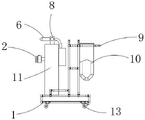
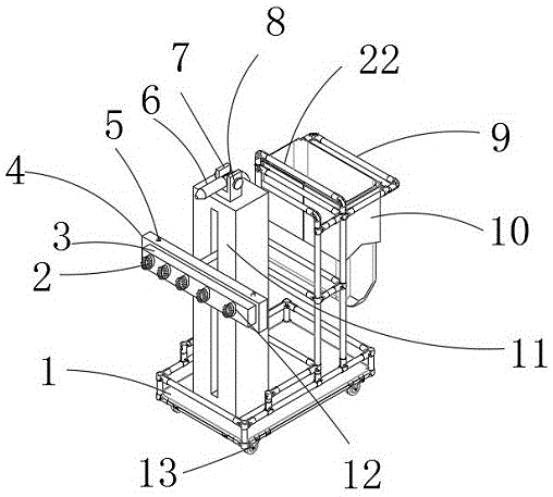
图1为本实用新型结构示意图;Fig. 1 is the structural representation of the utility model;
图2为本实用新型的前视图;Fig. 2 is the front view of the utility model;
图3为本实用新型中螺纹杆的结构示意图;Fig. 3 is the structural representation of threaded rod in the utility model;
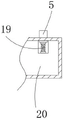
图4为本实用新型中插杆的结构示意图;Fig. 4 is the structural representation of inserting rod in the utility model;
图5为本实用新型中转动马达的结构示意图。Fig. 5 is a structural schematic diagram of the rotary motor in the present invention.
附图中,各标号所代表的部件列表如下:In the accompanying drawings, the list of parts represented by each label is as follows:
1、底板;2、刷毛;3、安装板;4、升降板;5、卡块;6、喷头;7、安装架;8、调节旋钮;9、推杆;10、收纳框;11、固定柱;12、转盘;13、锁止万向轮;14、从动齿轮;15、驱动电机;16、主动齿轮;17、螺纹杆;18、限位杆;19、压缩弹簧;20、插杆;21、转动马达;22、防护架。1. Bottom plate; 2. Bristles; 3. Mounting plate; 4. Lifting plate; 5. Block; 6. Nozzle; 7. Mounting frame; 8. Adjusting knob; 9. Push rod; 10. Storage frame; 11. Fixed Column; 12, turntable; 13, locking universal wheel; 14, driven gear; 15, driving motor; 16, driving gear; 17, threaded rod; 18, limit rod; 19, compression spring; 20, insertion rod ; 21, rotating motor; 22, protective frame.
具体实施方式detailed description
下面将结合本实用新型实施例中的附图,对本实用新型实施例中的技术方案进行清楚、完整地描述,显然,所描述的实施例仅仅是本实用新型一部分实施例,而不是全部的实施例。基于本实用新型中的实施例,本领域普通技术人员在没有作出创造性劳动前提下所获得的所有其它实施例,都属于本实用新型保护的范围。The technical solutions in the embodiments of the present invention will be clearly and completely described below in conjunction with the accompanying drawings in the embodiments of the present invention. Obviously, the described embodiments are only part of the embodiments of the present invention, not all of them. example. Based on the embodiments of the present utility model, all other embodiments obtained by persons of ordinary skill in the art without creative efforts belong to the scope of protection of the present utility model.
在本实用新型的描述中,需要理解的是,术语“上”、“中”、“外”、“内”等指示方位或位置关系,仅是为了便于描述本实用新型和简化描述,而不是指示或暗示所指的组件或元件必须具有特定的方位,以特定的方位构造和操作,因此不能理解为对本实用新型的限制。In the description of the present utility model, it should be understood that the terms "upper", "middle", "outer", "inner" and the like indicate orientation or positional relationship, and are only for the convenience of describing the present utility model and simplifying the description, rather than Any indication or implication that a referenced component or element must have a particular orientation, be constructed and operate in a particular orientation should not be construed as limiting the invention.
请参阅图1-图5所示,本实用新型为一种船舶维修用清洁装置,包括底板1,底板1的上表面固定连接有固定柱11,固定柱11的侧壁通过升降机构滑动连接有升降板4,升降板4的侧壁固定卡接机构固定安装有安装板3,安装板3的侧壁转动连接有转盘12,转盘12的侧壁固定连接有若干均匀分布的刷毛2,安装板3的内侧壁固定安装有转动马达21,转动马达21的输出端通过联轴器固定连接有转轴,转轴的一端伸出安装板3的侧壁并与转盘12的侧壁固定连接,卡接机构包括插杆20、安装槽、压缩弹簧19和卡块5,安装板3的侧壁固定连接有插杆20,插杆20伸入升降板4内并与其滑动连接,插杆20伸入升降板4内部上表面开设有安装槽,安装槽内滑动连接有卡块5,卡块5贯穿升降板4并与其滑动连接,安装槽内侧壁设置有压缩弹簧19,通过设置的安装板3、转盘12、刷毛2、转动马达21和转轴可便于带动转盘12进行自动转动清洁处理,同时通过设置的插杆20、安装槽、压缩弹簧19和卡块5可便于对安装板3进行快速拆卸更换,便于对刷毛2进行定期更换处理,提升装置的清洁效果,降低现有的清洗设备大多通过手动进行喷水擦拭清洗等,费时费力且清洗效率较差,难以对其进行自动清洗处理,大大降低了装置清洗效率的不便。Please refer to Fig. 1-shown in Fig. 5, the utility model is a kind of cleaning device for ship maintenance, comprising a
升降机构包括驱动电机15、升降板4、滑槽、主动齿轮16、从动齿轮14和螺纹杆17,固定柱11的上内壁固定安装有驱动电机15,驱动电机15的输出端通过联轴器固定连接有转杆,转杆的外表面固定套装有主动齿轮16,固定柱11的上下内壁之间转动连接有螺纹杆17,螺纹杆17的外表面固定套装有从动齿轮14,主动齿轮16和从动齿轮14啮合连接,螺纹杆17的外表面螺纹连接有升降板4,固定柱11的侧壁开设有滑槽,升降板4的一端伸出滑槽并与其滑动连接,通过设置的驱动电机15、升降板4、滑槽、主动齿轮16、从动齿轮14和螺纹杆17可便于对在清洁时对其进行自动升降处理,提升了装置的清洁效率,固定柱11的上下内壁之间固定连接有限位杆18,升降板4贯穿限位杆18并与其滑动连接,通过设置的限位杆18可便于在升降板4移动时提升其限位效果。The lifting mechanism includes a driving
固定柱11的上表面固定连接有安装架7,安装架7内通过调节机构转动连接有喷头6,喷头6的侧壁固定连通有输水管,固定柱11的侧壁固定安装有水箱,输水管伸入水箱内并与其固定连通,通过设置的安装架7和喷头6可便于在除尘清洁进行喷水清洁,提升装置的清洁效果,调节机构包括调节旋钮8和安装架7,安装架7的内壁之间转动连接有转动杆,转动杆贯穿喷头6侧壁并与其固定连接,转动杆的一端伸出安装架7侧壁并固定连接有调节旋钮8,通过设置的调节旋钮8和安装架7可便于对喷头6喷水方向进行调整。The upper surface of the fixed
底板1的上表面固定连接有防护架22,防护架22的侧壁固定连接有收纳框10,通过设置的收纳框10可向内放置清洁所需物品,底板1的下表面四角处均固定安装有锁止万向轮13,防护架22的侧壁固定连接有推杆9,通过设置的锁止万向轮13可推杆9可便于推动装置进行移动。The upper surface of the
如图1-图5所示,本实施例为一种船舶维修用清洁装置的使用方法:所述驱动电机15的型号为SY70BL-A004,所转动马达21的型号为5IK-5GU-10K,使用前将装置推至待清洁处后,转动调节旋钮8调整喷头6至合适位置后,启动喷头6开始进行喷水清洁,喷水时,通过设置的刷毛2开始进行擦拭清洁,擦拭清洁时启动转动马达21带动转盘12进行转动,从而带动刷毛2进行自动清洁处理,启动驱动电机15带动升降板4进行上下移动,提升装置的清洁效果,降低现有的清洗设备大多通过手动进行喷水擦拭清洗等,费时费力且清洗效率较差,难以对其进行自动清洗处理,大大降低了装置清洗效率的不便,当需要对刷毛2进行拆卸更换时,按压卡块5后直接将安装板3抽出即可对其进行快速拆卸更换处理。As shown in Figures 1-5, this embodiment is a method of using a cleaning device for ship maintenance: the model of the driving
在本说明书的描述中,参考术语“一个实施例”、“示例”、“具体示例”等的描述意指结合该实施例或示例描述的具体特征、结构、材料或者特点包含于本实用新型的至少一个实施例或示例中。在本说明书中,对上述术语的示意性表述不一定指的是相同的实施例或示例。而且,描述的具体特征、结构、材料或者特点可以在任何的一个或多个实施例或示例中以合适的方式结合。In the description of this specification, descriptions referring to the terms "one embodiment", "example", "specific example" and the like mean that the specific features, structures, materials or characteristics described in conjunction with the embodiment or example are included in the description of the present invention. In at least one embodiment or example. In this specification, schematic representations of the above terms do not necessarily refer to the same embodiment or example. Furthermore, the specific features, structures, materials or characteristics described may be combined in any suitable manner in any one or more embodiments or examples.
以上公开的本实用新型优选实施例只是用于帮助阐述本实用新型。优选实施例并没有详尽叙述所有的细节,也不限制该实用新型仅为所述的具体实施方式。显然,根据本说明书的内容,可作很多的修改和变化。本说明书选取并具体描述这些实施例,是为了更好地解释本实用新型的原理和实际应用,从而使所属技术领域技术人员能很好地理解和利用本实用新型。本实用新型仅受权利要求书及其全部范围和等效物的限制。The preferred embodiments of the present invention disclosed above are only used to help explain the present invention. The preferred embodiments do not exhaust all details, nor do they limit the utility model to the specific implementations described. Obviously, many modifications and variations can be made based on the contents of this specification. This specification selects and specifically describes these embodiments in order to better explain the principle and practical application of the utility model, so that those skilled in the art can well understand and utilize the utility model. The invention is to be limited only by the claims and their full scope and equivalents.
Claims (7)
Priority Applications (1)
| Application Number | Priority Date | Filing Date | Title |
|---|---|---|---|
| CN202221774374.5U CN218167917U (en) | 2022-07-11 | 2022-07-11 | Cleaning device for ship maintenance |
Applications Claiming Priority (1)
| Application Number | Priority Date | Filing Date | Title |
|---|---|---|---|
| CN202221774374.5U CN218167917U (en) | 2022-07-11 | 2022-07-11 | Cleaning device for ship maintenance |
Publications (1)
| Publication Number | Publication Date |
|---|---|
| CN218167917U true CN218167917U (en) | 2022-12-30 |
Family
ID=84611707
Family Applications (1)
| Application Number | Title | Priority Date | Filing Date |
|---|---|---|---|
| CN202221774374.5U Active CN218167917U (en) | 2022-07-11 | 2022-07-11 | Cleaning device for ship maintenance |
Country Status (1)
| Country | Link |
|---|---|
| CN (1) | CN218167917U (en) |
Cited By (2)
| Publication number | Priority date | Publication date | Assignee | Title |
|---|---|---|---|---|
| CN116274055A (en) * | 2023-02-03 | 2023-06-23 | 江苏开放大学(江苏城市职业学院) | A dust removal device for electromechanical equipment |
| CN118253457A (en) * | 2024-05-28 | 2024-06-28 | 南通远洋船舶配套有限公司 | Ship body surface treatment device for ship maintenance |
-
2022
- 2022-07-11 CN CN202221774374.5U patent/CN218167917U/en active Active
Cited By (2)
| Publication number | Priority date | Publication date | Assignee | Title |
|---|---|---|---|---|
| CN116274055A (en) * | 2023-02-03 | 2023-06-23 | 江苏开放大学(江苏城市职业学院) | A dust removal device for electromechanical equipment |
| CN118253457A (en) * | 2024-05-28 | 2024-06-28 | 南通远洋船舶配套有限公司 | Ship body surface treatment device for ship maintenance |
Similar Documents
| Publication | Publication Date | Title |
|---|---|---|
| CN206997145U (en) | A kind of cleaning plant for timber spray painting processing early stage | |
| CN215785492U (en) | Tank car cleaning device for concrete production | |
| CN114472280B (en) | A surface cleaning system for photovoltaic panels and cleaning method thereof | |
| CN217831107U (en) | Effluent water sump belt cleaning device with adjustable | |
| CN220922824U (en) | Cleaning device for concrete production | |
| CN219850973U (en) | A solar panel glass cleaning device | |
| CN220804819U (en) | Drainage facility maintenance device | |
| CN219710890U (en) | A kind of smoothing device for house construction | |
| CN217167970U (en) | Water conservancy construction pipeline surface rust cleaning device | |
| CN218982572U (en) | Cleaning device for natural gas conveying pipeline | |
| CN217203536U (en) | Road surface anti-dry-cracking spraying device | |
| CN212939595U (en) | A cleaner for building and decorating walls | |
| CN214289062U (en) | Repair equipment for repairing ancient building bricks | |
| CN214980086U (en) | Hydraulic engineering pipeline surface rust cleaning device | |
| CN212637449U (en) | Scrubbing mechanism for automatic car washer without dead angle | |
| CN116587118A (en) | Grinding equipment for jack base production | |
| CN223043183U (en) | A wear-resistant steel ball cleaning device | |
| CN216290830U (en) | Automatic snow sweeping device of photovoltaic panel for seismograph station | |
| CN223733349U (en) | Surface cleaner of photovoltaic power generation assembly glass plate | |
| CN113245254A (en) | Be used for coating roll scrubbing device | |
| CN220111402U (en) | Sewer pipeline surface processing paint spraying apparatus | |
| CN223394007U (en) | A cleaning structure of an external washing machine | |
| CN219451389U (en) | Mortar trowelling device for construction of cement flowers of outer walls of ancient buildings | |
| CN217604585U (en) | Positioning and drying device for liquid crystal display screen production | |
| CN219151051U (en) | Concrete admixture container cleaning device |
Legal Events
| Date | Code | Title | Description |
|---|---|---|---|
| GR01 | Patent grant | ||
| GR01 | Patent grant | ||
| PP01 | Preservation of patent right |
Effective date of registration: 20251118 Granted publication date: 20221230 |
|
| PP01 | Preservation of patent right |