CN218153986U - LED automobile lamp capable of adjusting irradiation angle during turning - Google Patents
LED automobile lamp capable of adjusting irradiation angle during turning Download PDFInfo
- Publication number
- CN218153986U CN218153986U CN202222448850.0U CN202222448850U CN218153986U CN 218153986 U CN218153986 U CN 218153986U CN 202222448850 U CN202222448850 U CN 202222448850U CN 218153986 U CN218153986 U CN 218153986U
- Authority
- CN
- China
- Prior art keywords
- fixed mounting
- bevel gear
- threaded column
- irradiation angle
- led automobile
- Prior art date
- Legal status (The legal status is an assumption and is not a legal conclusion. Google has not performed a legal analysis and makes no representation as to the accuracy of the status listed.)
- Active
Links
Images


Landscapes
- Lighting Device Outwards From Vehicle And Optical Signal (AREA)
Abstract
本实用新型涉及LED汽车灯技术领域,特别是涉及转弯可调节照射角度的LED汽车灯,包括底座和圆环连接架,所述圆环连接架圆周表面上下端均竖向贯穿开设有螺纹槽,所述圆环连接架内活动套接有灯壳,所述底座上端固定安装有支架,所述底座上端中间位置固定安装有圆柱,所述圆柱内开设有转动槽,所述支架上段右侧固定安装有矩形条,所述支架上段左侧固定安装有支撑板。本实用新型通过设置的电机带动转动杆,转动杆再带动第一锥齿轮和第二锥齿轮转动,以此来达到灯壳的转动,在汽车转弯时,车灯的转向角度能够通过电机进行角度调节,从而保证驾驶人员看清前方道路,安全性较高,不会发生车灯转动角度较小,影响驾驶人员对前方道路观察的现象。
The utility model relates to the technical field of LED automobile lamps, in particular to an LED automobile lamp with an adjustable irradiation angle when turning, comprising a base and a ring connecting frame, and thread grooves are vertically penetrated at the upper and lower ends of the circumferential surface of the ring connecting frame. The lamp housing is movably socketed in the ring connecting frame, a bracket is fixedly installed on the upper end of the base, a cylinder is fixedly installed in the middle position of the upper end of the base, a rotation groove is opened in the cylinder, and the upper part of the bracket is fixed on the right side. A rectangular strip is installed, and a support plate is fixedly installed on the left side of the upper section of the bracket. The utility model drives the rotating rod through the set motor, and the rotating rod drives the first bevel gear and the second bevel gear to rotate, so as to achieve the rotation of the lamp housing. When the car turns, the steering angle of the lamp can be adjusted by the motor. Adjustment, so as to ensure that the driver can see the road ahead, with high safety, and there will be no small turning angle of the headlights, which will affect the driver's observation of the road ahead.
Description
技术领域technical field
本实用新型涉及LED汽车灯技术领域,特别是涉及转弯可调节照射角度的LED汽车灯。The utility model relates to the technical field of LED automobile lamps, in particular to an LED automobile lamp whose irradiation angle can be adjusted when turning.
背景技术Background technique
汽车大灯,也称汽车前照灯、汽车LED日行灯,作为汽车的眼睛,不仅关系到一个车主的外在形象,更与夜间开车或坏天气条件下的安全驾驶紧密联系,车灯的使用及保养,是不可忽略的;Car headlights, also known as car headlights and car LED daytime running lights, as the eyes of a car, are not only related to the external image of a car owner, but also closely related to safe driving at night or in bad weather conditions. The use of car lights and maintenance cannot be ignored;
如中国专利公开了:一种用于转弯时可调节照射角度的LED汽车大灯,公开号:CN215489500U,通过控制电机控制车灯的方向,使得汽车转弯时,车灯的转向角度能够跟随转弯的角度变化,从而保证驾驶人员看清前方道路,安全性较高,不会发生车灯转动角度较小,影响驾驶人员对前方道路观察的现象,又该灯罩的内部设置有散热板、导热板等,可有效将车灯工作时产生的热量散出,从而保证车灯的使用寿命,利于使用;Disclosed as Chinese patent: a kind of LED car headlight that can adjust the irradiation angle when turning, publication number: CN215489500U, by controlling the direction of motor control light, when making car turn, the steering angle of car light can follow the direction of turning. The angle changes, so as to ensure that the driver can see the road ahead, and the safety is high, and the phenomenon that the rotation angle of the headlight is small will not affect the driver's observation of the road ahead, and the inside of the lampshade is equipped with a heat dissipation plate, a heat conduction plate, etc. , which can effectively dissipate the heat generated by the lights when they are working, thus ensuring the service life of the lights and facilitating their use;
在夜间汽车转弯行驶时,对弯道的道路照明有限,此时车灯不能照射汽车弯道处的道路,影响驾驶人员看清道路,安全性不高。When the car is turning at night, the road lighting on the bend is limited. At this time, the car lights cannot illuminate the road at the bend of the car, which affects the driver's ability to see the road clearly, and the safety is not high.
实用新型内容Utility model content
为了克服现有技术的不足,本实用新型提供转弯可调节照射角度的LED汽车灯,包括底座和圆环连接架,所述圆环连接架圆周表面上下端均竖向贯穿开设有螺纹槽,所述圆环连接架内活动套接有灯壳,所述底座上端固定安装有支架,所述底座上端中间位置固定安装有圆柱,所述圆柱内开设有转动槽,所述支架上段右侧固定安装有矩形条,所述支架上段左侧固定安装有支撑板,所述矩形条与支架横向贯穿开设有转动孔,所述矩形条下端固定安装有L形架,所述L形架右侧竖向贯穿开设有圆形孔,所述矩形条开设的转动孔内转动安装有转动杆,所述转动杆左侧端固定安装有电机,所述电机固定安装在支撑板上端,所述转动杆右侧端固定安装有第一锥齿轮。In order to overcome the deficiencies of the prior art, the utility model provides an LED car light with adjustable irradiation angle when turning, which includes a base and a ring connecting frame, and thread grooves are vertically penetrated at the upper and lower ends of the circumferential surface of the ring connecting frame. There is a lamp housing movable in the ring connecting frame, a bracket is fixedly installed on the upper end of the base, a cylinder is fixedly installed in the middle position of the upper end of the base, a rotation groove is opened in the cylinder, and the right side of the upper part of the bracket is fixedly installed. There is a rectangular bar, a support plate is fixedly installed on the left side of the upper part of the bracket, a rotation hole is provided through the horizontal passage of the rectangular bar and the bracket, an L-shaped frame is fixedly installed at the lower end of the rectangular bar, and the right side of the L-shaped frame is vertically A circular hole is opened through, and a rotating rod is installed in the rotating hole opened by the rectangular bar. The left end of the rotating rod is fixedly equipped with a motor, and the motor is fixedly installed on the top of the support plate. The right side of the rotating rod The first bevel gear is fixedly installed on the end.
为解决上述技术问题,本实用新型提供如下技术方案:In order to solve the above technical problems, the utility model provides the following technical solutions:
作为本实用新型的一种优选技术方案,所述第一锥齿轮圆周表面下端啮合有第二锥齿轮,所述第二锥齿轮下端固定安装有第二螺纹柱。As a preferred technical solution of the present invention, the lower end of the circumferential surface of the first bevel gear meshes with the second bevel gear, and the lower end of the second bevel gear is fixedly installed with a second threaded post.
作为本实用新型的一种优选技术方案,所述第二螺纹柱中间段转动安装在L形架开设的圆形孔内。As a preferred technical solution of the present invention, the middle section of the second threaded column is rotatably installed in the circular hole opened by the L-shaped frame.
作为本实用新型的一种优选技术方案,所述第二螺纹柱下段螺纹安装在圆环连接架上端开设的螺纹槽内,所述第二螺纹柱下端与灯壳圆周表面贴合。As a preferred technical solution of the present invention, the lower section of the second threaded column is threadedly installed in the threaded groove provided at the upper end of the ring connecting frame, and the lower end of the second threaded column is attached to the circumferential surface of the lamp housing.
作为本实用新型的一种优选技术方案,所述圆柱开设的转动槽内转动安装有第一螺纹柱。As a preferred technical solution of the utility model, the first threaded column is rotatably installed in the rotating groove provided by the cylinder.
作为本实用新型的一种优选技术方案,所述第一螺纹柱上段螺纹安装在圆环连接架下端开设的螺纹槽内,所述第一螺纹柱上端与灯壳圆周表面贴合。As a preferred technical solution of the present invention, the upper section of the first threaded column is threadedly installed in the threaded groove provided at the lower end of the ring connecting frame, and the upper end of the first threaded column is attached to the circumferential surface of the lamp housing.
与现有技术相比,本实用新型能达到的有益效果是:Compared with the prior art, the beneficial effects that the utility model can achieve are:
1、该转弯可调节照射角度的LED汽车灯,通过设置的电机带动转动杆,转动杆再带动第一锥齿轮和第二锥齿轮转动,以此来达到灯壳的转动,在汽车转弯时,车灯的转向角度能够通过电机进行角度调节,从而保证驾驶人员看清前方道路,安全性较高,不会发生车灯转动角度较小,影响驾驶人员对前方道路观察的现象。1. The LED car lights that can adjust the irradiation angle when turning, drive the rotating rod through the set motor, and the rotating rod drives the first bevel gear and the second bevel gear to rotate, so as to achieve the rotation of the lamp housing. When the car turns, The steering angle of the headlights can be adjusted by the motor, so as to ensure that the driver can see the road ahead, which has high safety and will not affect the driver's observation of the road ahead due to the small turning angle of the headlights.
2、该转弯可调节照射角度的LED汽车灯,通过设置的第二螺纹柱和第一螺纹柱,以及圆环连接架,使得该LED车灯在需要进行维修或更换时,可以进行拆卸,以方便维修人员对其进行更换。2. The LED car light whose turning angle can be adjusted can be disassembled when it needs to be repaired or replaced by the second threaded column, the first threaded column and the ring connecting frame. It is convenient for maintenance personnel to replace it.
附图说明Description of drawings
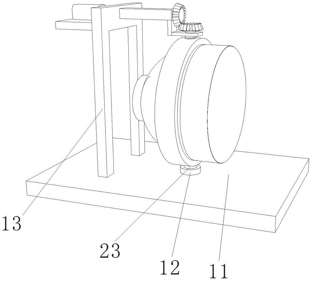
图1为本实用新型整体的结构示意图;Fig. 1 is the overall structural representation of the utility model;
图2为本实用新型底座的结构示意图;Fig. 2 is the structural representation of the base of the utility model;
图3为本实用新型圆环连接架的结构示意图;Fig. 3 is the structural representation of the utility model circular ring connector;
图4为本实用新型第一锥齿轮的结构示意图。Fig. 4 is a schematic structural diagram of the first bevel gear of the present invention.
其中:11、底座;12、圆柱;13、支架;14、圆形孔;15、L形架;16、矩形条;17、支撑板;21、灯壳;22、圆环连接架;23、第一螺纹柱;24、第二螺纹柱;25、转动杆;26、第一锥齿轮;27、第二锥齿轮。Among them: 11. Base; 12. Cylinder; 13. Bracket; 14. Round hole; 15. L-shaped frame; 16. Rectangular bar; 17. Support plate; 21. Lamp housing; 24, the second threaded column; 25, the rotating rod; 26, the first bevel gear; 27, the second bevel gear.
具体实施方式detailed description
为了使本实用新型实现的技术手段、创作特征、达成目的与功效易于明白了解,下面结合具体实施例,进一步阐述本实用新型,但下述实施例仅仅为本实用新型的优选实施例,并非全部。基于实施方式中的实施例,本领域技术人员在没有做出创造性劳动的前提下所获得其它实施例,都属于本实用新型的保护范围。下述实施例中的实验方法,如无特殊说明,均为常规方法,下述实施例中所用的材料、试剂等,如无特殊说明,均可从商业途径得到。In order to make the technical means, creative features, goals and effects of the utility model realized easy to understand, the utility model will be further elaborated below in conjunction with specific examples, but the following examples are only preferred embodiments of the utility model, not all . Based on the examples in the implementation manners, other examples obtained by those skilled in the art without making creative efforts all belong to the protection scope of the present utility model. The experimental methods in the following examples, unless otherwise specified, are conventional methods, and the materials, reagents, etc. used in the following examples, unless otherwise specified, can be obtained from commercial sources.
实施例:Example:
如图1、图2、图3、图4所示,转弯可调节照射角度的LED汽车灯,包括底座11和圆环连接架22,圆环连接架22圆周表面上下端均竖向贯穿开设有螺纹槽,圆环连接架22内活动套接有灯壳21,底座11上端固定安装有支架13,在使用该转弯可调节照射角度的LED汽车灯时,通过电机带动转动杆25转动,使得转动杆25在矩形条16和支架13开设的转动孔转动,转动杆25便会带动第一锥齿轮26转动,而通过第一锥齿轮26与第二锥齿轮27的啮合,第一锥齿轮26带动第二锥齿轮27转动,当第二锥齿轮27转动后会带动第二螺纹柱24转动,而第二螺纹柱24与圆环连接架22以及灯壳21螺纹连接紧固,第二螺纹柱24便会带动圆环连接架22和灯壳21进行转动,以此达到了LED汽车灯的角度调节,底座11上端中间位置固定安装有圆柱12,圆柱12内开设有转动槽,支架13上段右侧固定安装有矩形条16,支架13上段左侧固定安装有支撑板17,矩形条16与支架13横向贯穿开设有转动孔,矩形条16下端固定安装有L形架15,L形架15右侧竖向贯穿开设有圆形孔14,矩形条16开设的转动孔内转动安装有转动杆25,转动杆25左侧端固定安装有电机,电机固定安装在支撑板17上端,转动杆25右侧端固定安装有第一锥齿轮26。第一锥齿轮26圆周表面下端啮合有第二锥齿轮27,第二锥齿轮27下端固定安装有第二螺纹柱24。进一步的该转弯可调节照射角度的LED汽车灯在需要对灯壳21进行更换或维修时,拧松第二螺纹柱24,使得第二螺纹柱24与灯壳21圆周表面分离,此时即可将圆环连接架22带着灯壳21向上提起,使第一螺纹柱23从圆柱12开设的转动槽内移出,再拧松第一螺纹柱23,使得第一螺纹柱23与灯壳21分离,此时即可将灯壳21与圆环连接架22分离,第二螺纹柱24中间段转动安装在L形架15开设的圆形孔14内。第二螺纹柱24下段螺纹安装在圆环连接架22上端开设的螺纹槽内,第二螺纹柱24下端与灯壳21圆周表面贴合。圆柱12开设的转动槽内转动安装有第一螺纹柱23。第一螺纹柱23上段螺纹安装在圆环连接架22下端开设的螺纹槽内,第一螺纹柱23上端与灯壳21圆周表面贴合,该装置通过设置的电机带动转动杆25,转动杆25再带动第一锥齿轮26和第二锥齿轮27转动,以此来达到灯壳21的转动,在汽车转弯时,车灯的转向角度能够通过电机进行角度调节,从而保证驾驶人员看清前方道路,安全性较高,不会发生车灯转动角度较小,影响驾驶人员对前方道路观察的现象。同时该装置通过设置的第二螺纹柱24和第一螺纹柱23,以及圆环连接架22,使得该LED车灯在需要进行维修或更换时,可以进行拆卸,以方便维修人员对其进行更换。As shown in Fig. 1, Fig. 2, Fig. 3, and Fig. 4, the LED car lamp with adjustable irradiation angle when turning includes a
使用说明:在使用该转弯可调节照射角度的LED汽车灯时,通过电机带动转动杆25转动,使得转动杆25在矩形条16和支架13开设的转动孔转动,转动杆25便会带动第一锥齿轮26转动,而通过第一锥齿轮26与第二锥齿轮27的啮合,第一锥齿轮26带动第二锥齿轮27转动,当第二锥齿轮27转动后会带动第二螺纹柱24转动,而第二螺纹柱24与圆环连接架22以及灯壳21螺纹连接紧固,第二螺纹柱24便会带动圆环连接架22和灯壳21进行转动,以此达到了LED汽车灯的角度调节;Instructions for use: When using the LED car light with adjustable irradiation angle, the motor drives the rotating
进一步的该转弯可调节照射角度的LED汽车灯在需要对灯壳21进行更换或维修时,拧松第二螺纹柱24,使得第二螺纹柱24与灯壳21圆周表面分离,此时即可将圆环连接架22带着灯壳21向上提起,使第一螺纹柱23从圆柱12开设的转动槽内移出,再拧松第一螺纹柱23,使得第一螺纹柱23与灯壳21分离,此时即可将灯壳21与圆环连接架22分离。该装置通过设置的电机带动转动杆25,转动杆25再带动第一锥齿轮26和第二锥齿轮27转动,以此来达到灯壳21的转动,在汽车转弯时,车灯的转向角度能够通过电机进行角度调节,从而保证驾驶人员看清前方道路,安全性较高,不会发生车灯转动角度较小,影响驾驶人员对前方道路观察的现象。同时该装置通过设置的第二螺纹柱24和第一螺纹柱23,以及圆环连接架22,使得该LED车灯在需要进行维修或更换时,可以进行拆卸,以方便维修人员对其进行更换。Further, when the turnable LED car lamp with adjustable irradiation angle needs to replace or repair the
上面结合附图对本实用新型的实施方式作了详细说明,但是本实用新型并不限于此,在所属技术领域的技术人员所具备的知识范围内,在不脱离本实用新型宗旨的前提下还可以作出各种变化。Above, the embodiment of the present utility model has been described in detail in conjunction with the accompanying drawings, but the present utility model is not limited thereto. Make various changes.
Claims (6)
Priority Applications (1)
| Application Number | Priority Date | Filing Date | Title |
|---|---|---|---|
| CN202222448850.0U CN218153986U (en) | 2022-09-15 | 2022-09-15 | LED automobile lamp capable of adjusting irradiation angle during turning |
Applications Claiming Priority (1)
| Application Number | Priority Date | Filing Date | Title |
|---|---|---|---|
| CN202222448850.0U CN218153986U (en) | 2022-09-15 | 2022-09-15 | LED automobile lamp capable of adjusting irradiation angle during turning |
Publications (1)
| Publication Number | Publication Date |
|---|---|
| CN218153986U true CN218153986U (en) | 2022-12-27 |
Family
ID=84563429
Family Applications (1)
| Application Number | Title | Priority Date | Filing Date |
|---|---|---|---|
| CN202222448850.0U Active CN218153986U (en) | 2022-09-15 | 2022-09-15 | LED automobile lamp capable of adjusting irradiation angle during turning |
Country Status (1)
| Country | Link |
|---|---|
| CN (1) | CN218153986U (en) |
Cited By (1)
| Publication number | Priority date | Publication date | Assignee | Title |
|---|---|---|---|---|
| CN119879123A (en) * | 2025-03-20 | 2025-04-25 | 浙江宏冠科技股份有限公司 | Adaptive steering dimming vehicle lamp |
-
2022
- 2022-09-15 CN CN202222448850.0U patent/CN218153986U/en active Active
Cited By (1)
| Publication number | Priority date | Publication date | Assignee | Title |
|---|---|---|---|---|
| CN119879123A (en) * | 2025-03-20 | 2025-04-25 | 浙江宏冠科技股份有限公司 | Adaptive steering dimming vehicle lamp |
Similar Documents
| Publication | Publication Date | Title |
|---|---|---|
| CN108099760B (en) | A kind of car headlight with easy angle adjustment | |
| CN102923046A (en) | Automobile headlamp adjusting device with spherical pair structure | |
| CN216591514U (en) | Automobile headlamp with multi-angle dimming mounting structure | |
| CN113587045A (en) | LED automobile headlamp capable of adjusting irradiation angle during turning | |
| CN211731197U (en) | Dimming mechanism for automobile headlamp | |
| CN210822017U (en) | An intelligent vehicle lamp with adaptive brightness and angle | |
| CN215489500U (en) | LED automobile headlamp capable of adjusting irradiation angle during turning | |
| CN112248920B (en) | Automobile headlamp convenient to install | |
| CN217320197U (en) | Automobile headlamp light-emitting angle rotating assembly | |
| CN214689243U (en) | Car far and near light control device | |
| CN212537703U (en) | Antifog street lamp | |
| CN212157018U (en) | An adjustable motorcycle headlight | |
| CN223635983U (en) | A type of car headlight that increases visibility | |
| CN219867540U (en) | Dimming support structure of automobile lamp | |
| CN221611196U (en) | Automatic light regulator for car lamp | |
| CN111442238B (en) | Matrix type all-weather lamp | |
| CN222352138U (en) | Angle-adjustable headlight | |
| CN209262970U (en) | A kind of LED floodlight facilitating adjusting | |
| CN216644078U (en) | Focusable motorcycle tricycle headlight | |
| CN218001357U (en) | Self-adaptive intelligent high beam control system | |
| CN223635982U (en) | Automotive headlight adjustment limit mechanism | |
| CN101893196B (en) | Automobile headlight | |
| CN220981097U (en) | Car light with defogging function | |
| CN219328050U (en) | Electric bicycle lamp | |
| CN221881216U (en) | A beach vehicle lighting device that is easy to adjust |
Legal Events
| Date | Code | Title | Description |
|---|---|---|---|
| GR01 | Patent grant | ||
| GR01 | Patent grant | ||
| TR01 | Transfer of patent right | ||
| TR01 | Transfer of patent right |
Effective date of registration: 20250616 Address after: 212300 Xinqiao Industrial Park, Danbei Town, Zhenjiang City, Jiangsu Province Patentee after: Jiangsu Quantum Automobile Industry Co.,Ltd. Country or region after: China Address before: 518100, Guangdong Province, Shenzhen City, Bao'an District, Fuhai Street, He Ping Community, Chongqing Road Xin Fu Industrial Park, Building 7 of Area B, 4th Floor Patentee before: SHENZHEN NEWCASTLE TECHNOLOGY Co.,Ltd. Country or region before: China |