CN218136835U - Lifting type surface grinding machine guide rail table - Google Patents
Lifting type surface grinding machine guide rail table Download PDFInfo
- Publication number
- CN218136835U CN218136835U CN202221756340.3U CN202221756340U CN218136835U CN 218136835 U CN218136835 U CN 218136835U CN 202221756340 U CN202221756340 U CN 202221756340U CN 218136835 U CN218136835 U CN 218136835U
- Authority
- CN
- China
- Prior art keywords
- guide rail
- table body
- fixedly mounted
- groove
- grinding machine
- Prior art date
- Legal status (The legal status is an assumption and is not a legal conclusion. Google has not performed a legal analysis and makes no representation as to the accuracy of the status listed.)
- Active
Links
- 238000012545 processing Methods 0.000 claims abstract description 11
- 230000005540 biological transmission Effects 0.000 claims abstract description 9
- 230000003028 elevating effect Effects 0.000 claims description 5
- 238000003754 machining Methods 0.000 claims description 4
- 238000000034 method Methods 0.000 abstract description 5
- 230000008859 change Effects 0.000 abstract description 3
- 230000000694 effects Effects 0.000 abstract description 3
- 230000002035 prolonged effect Effects 0.000 description 2
- 238000005096 rolling process Methods 0.000 description 2
- 230000004075 alteration Effects 0.000 description 1
- 230000009286 beneficial effect Effects 0.000 description 1
- 238000004891 communication Methods 0.000 description 1
- 230000007547 defect Effects 0.000 description 1
- 238000013461 design Methods 0.000 description 1
- 230000002427 irreversible effect Effects 0.000 description 1
- 238000012986 modification Methods 0.000 description 1
- 230000004048 modification Effects 0.000 description 1
- 230000008569 process Effects 0.000 description 1
Images


Landscapes
- Grinding Of Cylindrical And Plane Surfaces (AREA)
Abstract
The utility model discloses an over-and-under type flat grinder guide rail platform, including the grinding machine device, the top surface fixed mounting of grinding machine device bottom has the base frame, and the top fixed mounting of base frame has the guide rail platform, and the inside slidable mounting of guide rail platform has horizontal processing platform. In the above scheme, one end at the screw rod is cup jointed through the output shaft with current drive arrangement, thereby drive the transmission piece and carry out the round trip movement, make the work piece can be processed always, the in-process of removal, the pulley makes a round trip to rotate in the inside of half slot, make both friction reduce, reducing wear, increase of service life, when clamping device need go up and down, drive the second stage body through the drive connecting seat and carry out holistic lift, make the device go up and down, thereby clamping device's whole clamping position does not need the capping with the fixed condition, bearing capacity need not change yet, clamping device's practicality in the course of working has been guaranteed, the effect of guaranteeing whole device processing security and increase of service life has been reached.
Description
Technical Field
The utility model relates to a flat grinder technical field, more specifically says, the utility model relates to an over-and-under type flat grinder guide rail platform.
Background
The surface grinding machine is a device capable of grinding an object, and comprises a base, a clamping device, a grinding cutter and other main parts from bottom to top, wherein the clamping device is generally placed on a placing table, and the placing table is connected with the base so as to realize the linkage of the clamping device and the base.
However, in practical use, there still exist some disadvantages, such as: most of the existing placing tables can be transmitted through guide rails and can be called as guide rail tables, some clamping devices on the guide rail tables have lifting functions, but in the machining process, the clamping devices are small in size, so that the supporting limit after lifting is limited, large-scale machining cannot be conducted, the clamping devices can be damaged after a long time, and the normal use of the whole equipment is further influenced.
SUMMERY OF THE UTILITY MODEL
In order to overcome the above-mentioned defect of prior art, the embodiment of the utility model provides an over-and-under type flat grinder guide rail platform to it is limited that the elevating system who solves clamping device for the prior art show makes its bearing capacity itself, uses and can produce irreversible damage to it after a long time, and then influences the problem of the processing work of whole equipment.
In order to solve the technical problem, the utility model provides a following technical scheme: the utility model provides a lifting type surface grinding machine guide rail platform, includes the grinding machine device, the top surface fixed mounting of grinding machine device bottom has the base, the top fixed mounting of base has the guide rail platform, the inside slidable mounting of guide rail platform has horizontal processing platform.
The base table comprises a first table body, a groove is formed in the surface of the first table body, a connecting seat is fixedly mounted on the top surface of the groove, a hydraulic column is fixedly mounted at the top end of the connecting seat, and the bottom surface of the first table body is fixedly mounted at the top of the bottom surface of the grinding machine device.
The guide rail platform comprises a second platform body, an embedded plate is integrally formed at the bottom end of the second platform body, the embedded plate is matched with the groove in shape, a semicircular groove is formed in the inner wall of the top end of the second platform body, supporting grooves are formed in the upper side and the lower side of the semicircular groove and located on the surface of the second platform body, the bottom surface inside the second platform body is fixedly installed at the top end of a hydraulic column, and the second platform body is connected with the first platform body through the hydraulic column, so that the whole guide rail platform can be lifted up and down.
The horizontal machining table comprises a mounting plate, a screw rod is installed in the mounting plate in a rotating mode, a transmission block is installed on the surface of the screw rod in a threaded mode, a placing table is integrally formed at the top end of the transmission block, a clamping device is fixedly installed on the top face of the placing table, connecting frames are fixedly installed on the left side and the right side of the bottom end of the placing table, supporting columns are fixedly installed at the outer ends of the connecting frames, and pulleys are installed on the surface of the supporting columns in a rotating mode.
The bottom surface fixed mounting of mounting panel is at the middle part of second stage body top surface, the equal slidable mounting in the inside of supporting the groove in upper and lower both ends of support column, the pulley rotates to be installed in the inside of semicircle groove, utilizes the pulley to realize rolling friction to make whole when removing, both can keep spacing, also can reduce to a certain extent between the two because the loss that the friction produced, prolonged the practicality life-span of integrated device.
The utility model discloses an above-mentioned technical scheme's beneficial effect as follows:
in the above scheme, cup joint the one end at the screw rod through the output shaft with current drive arrangement, thereby drive the transmission piece and carry out round trip movement, make the inside work piece of clamping device can polish always, the in-process of removal, the pulley makes a round trip to rotate in the inside of half slot, make both friction reduce, reduce wear and tear, increase of service life, when clamping device need go up and down, drive the second stage body through the drive connecting seat and carry out holistic lift, make the device wholly go up and down, thereby clamping device's whole clamping position does not need the capping with the fixed condition, bearing capacity need not change yet, clamping device's practicality in the course of working has been guaranteed, the effect of guaranteeing whole device processing security and increase of service life has been reached.
Drawings
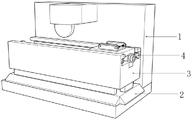
Fig. 1 is a schematic view of the overall structure of the present invention;
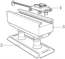
FIG. 2 is a perspective assembly view of the integrated device of the present invention;
FIG. 3 is a schematic view of the structure of the base platform of the present invention;
fig. 4 is a schematic structural view of the track table of the present invention;
fig. 5 is a schematic structural view of the horizontal processing table of the present invention.
[ reference numerals ]
1. A grinding machine device; 2. a base table; 3. a rail table; 4. a horizontal processing table; 21. a first stage body; 22. a groove; 23. a connecting seat; 24. a hydraulic column; 31. a second stage body; 32. a tabling plate; 33. a semicircular groove; 34. a support groove; 41. mounting a plate; 42. a screw; 43. a transmission block; 44. a placing table; 45. a clamping device; 46. a connecting frame; 47. a support pillar; 48. a pulley.
Detailed Description
To make the technical problems, technical solutions and advantages of the present invention clearer, the following description is made in conjunction with the accompanying drawings and specific embodiments.
The embodiment of the utility model provides an over-and-under type flat grinder guide rail platform as attached figure 1 to figure 5, including grinding machine device 1, the top surface fixed mounting of grinding machine device 1 bottom has base frame 2, the top fixed mounting of base frame 2 has guide rail platform 3, guide rail platform 3's inside slidable mounting has horizontal processing platform 4.
As shown in fig. 2 to 3, the base table 2 includes a first table body 21, a groove 22 is formed in the surface of the first table body 21, a connecting seat 23 is fixedly installed on the top surface of the groove 22, a hydraulic column 24 is fixedly installed at the top end of the connecting seat 23, and the bottom surface of the first table body 21 is fixedly installed at the top of the bottom surface of the grinding machine device 1.
As shown in fig. 4 to 5, the guide rail table 3 includes a second table body 31, a fitting plate 32 is integrally formed at a bottom end of the second table body 31, the fitting plate 32 is matched with the groove 22 in shape, a semicircular groove 33 is formed in an inner wall of a top end of the second table body 31, support grooves 34 are respectively formed in upper and lower sides of the semicircular groove 33, the support grooves 34 are located on a surface of the second table body 31, a bottom surface of an inner portion of the second table body 31 is fixedly mounted at a top end of a hydraulic cylinder 24, the second table body 31 and the first table body 21 are connected through the hydraulic cylinder 24, so that the whole body can be lifted up and down, the horizontal processing table 4 includes a mounting plate 41, a screw rod 42 is rotatably mounted in the mounting plate 41, and a transmission block 43 is threadedly mounted on a surface of the screw rod 42, the top end of the transmission block 43 is integrally formed with a placing table 44, the top surface of the placing table 44 is fixedly provided with a clamping device 45, the left side and the right side of the bottom end of the placing table 44 are fixedly provided with connecting frames 46, the outer end of each connecting frame 46 is fixedly provided with a supporting column 47, the surface of each supporting column 47 is rotatably provided with a pulley 48, the bottom surface of the mounting plate 41 is fixedly arranged in the middle of the top surface of the second table body 31, the upper end and the lower end of each supporting column 47 are slidably arranged in the corresponding supporting groove 34, the pulleys 48 are rotatably arranged in the corresponding semicircular grooves 33, and rolling friction is realized by the pulleys 48, so that the whole body can be kept in a limiting state when moving, loss between the two bodies due to friction can be reduced to a certain extent, and the practical service life of the whole device is prolonged.
The working process of the utility model is as follows:
above-mentioned scheme, the one end at screw rod 42 is cup jointed through the output shaft with current drive arrangement, thereby drive the driving block 43 and carry out the round trip movement, make the inside work piece of clamping device 45 can polish always, the in-process of removal, pulley 48 makes a round trip to rotate in the inside of half slot 33, make both frictions reduce, reduce wear, increase of service life, when clamping device 45 need go up and down, it carries out holistic lift to drive second stage body 31 through drive connecting seat 23, make the device wholly go up and down, thereby clamping device 45's whole clamping position does not need the capping with the fixed condition, bearing capacity also need not change, clamping device 45's practicality in the course of working has been guaranteed, the effect of guaranteeing whole device processing safety nature and increase of service life has been reached.
The points to be finally explained are: first, in the description of the present application, it should be noted that, unless otherwise specified and limited, the terms "mounted," "connected," "connecting," and "connecting" should be understood broadly, and may be a mechanical connection or an electrical connection, or a communication between two elements, and may be directly connected, and "upper," "lower," "left," and "right" are only used to indicate relative positional relationships, and when the absolute position of the object to be described is changed, the relative positional relationships may be changed;
secondly, the method comprises the following steps: in the drawings of the disclosed embodiments of the present invention, only the structures related to the disclosed embodiments are referred to, and other structures can refer to the common design, and under the condition of no conflict, the same embodiment and different embodiments of the present invention can be combined with each other;
and finally: the foregoing is illustrative of the preferred embodiments of the present invention, and is not to be construed as limiting the invention, and any modifications, equivalent alterations, improvements and the like made within the spirit and principle of the invention are intended to be included within the scope of the invention.
Claims (5)
1. The utility model provides a over-and-under type flat grinder guide rail platform, includes grinding machine device (1), its characterized in that, the top surface fixed mounting of grinding machine device (1) bottom has base frame (2), the top fixed mounting of base frame (2) has guide rail platform (3), the inside slidable mounting of guide rail platform (3) has horizontal processing platform (4).
2. The elevating flat grinder guide rail table according to claim 1, wherein the base table (2) comprises a first table body (21), a groove (22) is formed in the surface of the first table body (21), a connecting seat (23) is fixedly mounted on the top surface of the groove (22), a hydraulic column (24) is fixedly mounted on the top end of the connecting seat (23), and the bottom surface of the first table body (21) is fixedly mounted on the top of the bottom surface of the grinder device (1).
3. The elevating flat grinder guide rail table as claimed in claim 1, wherein the guide rail table (3) comprises a second table body (31), an embedded plate (32) is integrally formed at the bottom end of the second table body (31), the embedded plate (32) is matched with the groove (22) in shape, a semicircular groove (33) is formed in the inner wall of the top end of the second table body (31), support grooves (34) are formed in the upper side and the lower side of the semicircular groove (33), the support grooves (34) are located on the surface of the second table body (31), and the bottom surface inside the second table body (31) is fixedly mounted at the top end of the hydraulic column (24).
4. The elevating flat grinder guide rail table as claimed in claim 1, wherein the horizontal machining table (4) comprises a mounting plate (41), a screw (42) is rotatably mounted inside the mounting plate (41), a transmission block (43) is threadedly mounted on the surface of the screw (42), a placing table (44) is integrally formed at the top end of the transmission block (43), a clamping device (45) is fixedly mounted on the top surface of the placing table (44), connecting frames (46) are fixedly mounted on the left and right sides of the bottom end of the placing table (44), supporting columns (47) are fixedly mounted at the outer ends of the connecting frames (46), and pulleys (48) are rotatably mounted on the surface of the supporting columns (47).
5. The elevating flat grinder guide rail table as claimed in claim 4, wherein the bottom surface of the mounting plate (41) is fixedly installed at the middle of the top surface of the second table body (31), the upper and lower ends of the supporting column (47) are slidably installed inside the supporting groove (34), and the pulley (48) is rotatably installed inside the semicircular groove (33).
Priority Applications (1)
| Application Number | Priority Date | Filing Date | Title |
|---|---|---|---|
| CN202221756340.3U CN218136835U (en) | 2022-07-09 | 2022-07-09 | Lifting type surface grinding machine guide rail table |
Applications Claiming Priority (1)
| Application Number | Priority Date | Filing Date | Title |
|---|---|---|---|
| CN202221756340.3U CN218136835U (en) | 2022-07-09 | 2022-07-09 | Lifting type surface grinding machine guide rail table |
Publications (1)
| Publication Number | Publication Date |
|---|---|
| CN218136835U true CN218136835U (en) | 2022-12-27 |
Family
ID=84591542
Family Applications (1)
| Application Number | Title | Priority Date | Filing Date |
|---|---|---|---|
| CN202221756340.3U Active CN218136835U (en) | 2022-07-09 | 2022-07-09 | Lifting type surface grinding machine guide rail table |
Country Status (1)
| Country | Link |
|---|---|
| CN (1) | CN218136835U (en) |
-
2022
- 2022-07-09 CN CN202221756340.3U patent/CN218136835U/en active Active
Similar Documents
| Publication | Publication Date | Title |
|---|---|---|
| CN205631014U (en) | Gantry type stone cutting machine | |
| CN111745409B (en) | Multifunctional processing device for aluminum profile processing | |
| CN111015420B (en) | Deburring device for sheet metal processing | |
| CN212095906U (en) | Mounting seat for bearing machining | |
| CN210588466U (en) | Rotating device of roller convenient to polish | |
| CN212169837U (en) | Flange hole grinding device | |
| CN220783296U (en) | Petroleum machinery gear accessory abrasive machining machinery | |
| CN209936575U (en) | Grinding device is used in bearing processing of convenient regulation | |
| CN215239215U (en) | Mechanical stamping accessory is polished and drilling integration equipment | |
| CN219380062U (en) | Bearing grinding device | |
| CN216327042U (en) | Grinding device is used in processing of deep groove ball bearing outer loop | |
| CN212470503U (en) | Lock cylinder punching chamfering device | |
| CN211220100U (en) | Sampling detection device for clothing production | |
| CN213505799U (en) | Multi-axis synchronous jacking mechanism with pre-clearance | |
| CN212887019U (en) | Fine grinder with positioning structure for main shaft machining | |
| CN213004385U (en) | Novel numerical control servo drive grinding tool rest of numerical control shaft diameter turning and grinding machine | |
| CN211393727U (en) | Rotary lifting self-positioning platform | |
| CN209491593U (en) | A kind of workpiece lumen burr remover | |
| CN222136023U (en) | Dual-purpose exhaust line device for small tire components | |
| CN207175247U (en) | A kind of slidingtype gantry crane easy to use | |
| CN218461941U (en) | Adjustable multi-angle type clamping tool for machining deep groove ball bearing | |
| CN220007256U (en) | Bearing ring outer wall burr clearing device | |
| CN211517122U (en) | Power mechanism of grinding and polishing equipment | |
| CN222680505U (en) | A mining machinery corner grinding device | |
| CN221065964U (en) | Stable lifting machine |
Legal Events
| Date | Code | Title | Description |
|---|---|---|---|
| GR01 | Patent grant | ||
| GR01 | Patent grant |