CN218136557U - Crankshaft milling tool - Google Patents
Crankshaft milling tool Download PDFInfo
- Publication number
- CN218136557U CN218136557U CN202221765277.XU CN202221765277U CN218136557U CN 218136557 U CN218136557 U CN 218136557U CN 202221765277 U CN202221765277 U CN 202221765277U CN 218136557 U CN218136557 U CN 218136557U
- Authority
- CN
- China
- Prior art keywords
- rotating
- plate
- bottom plate
- sliding plate
- ball screw
- Prior art date
- Legal status (The legal status is an assumption and is not a legal conclusion. Google has not performed a legal analysis and makes no representation as to the accuracy of the status listed.)
- Active
Links
- 238000003801 milling Methods 0.000 title claims abstract description 20
- 238000003754 machining Methods 0.000 abstract description 2
- 238000005553 drilling Methods 0.000 description 5
- 238000010079 rubber tapping Methods 0.000 description 5
- 238000010586 diagram Methods 0.000 description 3
- 230000000694 effects Effects 0.000 description 1
- 238000005516 engineering process Methods 0.000 description 1
- 238000000034 method Methods 0.000 description 1
Images


Landscapes
- Jigs For Machine Tools (AREA)
Abstract
The utility model relates to the technical field of crankshaft machining, in particular to a crankshaft milling tool, which comprises a bottom plate and a moving assembly; the movable assembly comprises a ball screw, a guide rod, a sliding plate, a main clamping block, a driving motor and a clamping component, the sliding plate is installed on the bottom plate, the clamping component and the main clamping block are installed on the sliding plate, the sliding plate is connected with the guide rod in a sliding mode, the sliding plate can move through the ball screw, the rotation of the ball screw can be converted into linear motion of the sliding plate, so far, the driving motor drives the ball screw to rotate, the sliding plate can slide on the bottom plate along the guide rod, the main clamping block can be adjusted in position through sliding of the sliding plate, the crankshaft with different lengths can be clamped, and the crankshaft milling tool is wide in application range.
Description
Technical Field
The utility model relates to a bent axle processing technology field especially relates to a bent axle mills frock.
Background
The existing crankshaft is one of key parts of an engine, the crankshaft needs to be clamped in milling machining, the traditional crankshaft fixture tool is simple in structure, the fixture is fastened manually to fix the crankshaft, operation is complex, and working efficiency is low.
The existing crankshaft drilling and tapping clamp is provided with a cylinder on the left side of a main clamping block, and a pressure rod is pulled through the cylinder, so that an auxiliary clamping block on the pressure rod clamps a connecting shaft of a crankshaft, the clamping block is driven to move through the cylinder, the problems that the clamp needs to be manually fastened and operated complicatedly, the work efficiency is low are solved, the clamping speed of the cylinder clamping block is high, the operation is simple, and the work efficiency is high.
When the clamping device of the crankshaft drilling tapping clamp is fixed on the bottom plate, the crankshaft drilling tapping clamp cannot move and be adjusted, so that the crankshaft drilling tapping clamp can only be used for clamping a crankshaft with one length, and the application range is low.
SUMMERY OF THE UTILITY MODEL
An object of the utility model is to provide a bent axle mills frock, the clamping device who has solved current bent axle drilling tapping clamp fixes on the bottom plate, and unable activity and regulation lead to can only be used for the bent axle centre gripping to a length, lead to the problem that application scope is low.
In order to achieve the purpose, the utility model provides a crankshaft milling tool, which comprises a bottom plate,
also includes a moving assembly;
the moving assembly comprises a ball screw, a guide rod, a sliding plate, a main clamping block, a driving motor and a clamping member, the bottom plate is provided with a sliding groove, the ball screw is rotatably connected with the bottom plate and is positioned in the sliding groove, the guide rod is fixedly connected with the bottom plate and is positioned on one side of the bottom plate close to the ball screw, the sliding plate is connected with the ball screw and is slidably connected with the guide rod and is positioned on one side of the ball screw close to the guide rod, the main clamping block is fixedly connected with the sliding plate and is positioned on one side of the sliding plate far away from the ball screw, the driving motor is connected with the bottom plate and is connected with the ball screw and is positioned on one side of the bottom plate close to the ball screw, and the clamping member is connected with the sliding plate.
The clamping component comprises a base and a main shaft, wherein the base is fixedly connected with the sliding plate and is positioned on one side, close to the main clamping block, of the sliding plate; the main shaft is rotatably connected with the base and is positioned on one side of the base, which is far away from the sliding plate.
The clamping component further comprises a rotating connecting rod, the rotating connecting rod is connected with the spindle in a rotating mode and is located on one side, far away from the base, of the spindle.
The clamping member further comprises a clamping cylinder, the clamping cylinder is connected with the sliding plate, is rotatably connected with the rotating connecting rod and is positioned on one side, close to the rotating connecting rod, of the sliding plate.
The clamping component further comprises an auxiliary clamping block, and the auxiliary clamping block is fixedly connected with the main shaft and is positioned on one side, far away from the base, of the main shaft.
The crankshaft milling tool further comprises a rotating assembly, and the rotating assembly is connected with the bottom plate.
The rotating assembly comprises a rotating plate, a rotating clamping block and a pushing cylinder, and the rotating plate is rotatably connected with the bottom plate and is positioned on one side of the bottom plate, which is far away from the sliding plate; the rotating clamping block is connected with the rotating plate in a sliding mode and is positioned on one side, far away from the bottom plate, of the rotating plate; the pushing cylinder is connected with the rotating clamping block and is positioned on one side, close to the rotating plate, of the rotating clamping block.
The rotating assembly further comprises a rotating motor, the rotating motor is connected with the bottom plate, connected with the rotating plate and located on one side, close to the rotating plate, of the bottom plate.
The utility model discloses a bent axle mills frock install on the bottom plate the sliding plate install the centre gripping component on the sliding plate with main clamp splice, the sliding plate with guide bar sliding connection, the sliding plate passes through ball can realize removing, ball's rotation can convert into the linear motion of sliding plate, so far, driving motor drives ball rotates, the sliding plate can be along the guide bar is in slide on the bottom plate, through the slip realization of sliding plate is right the regulation of main clamp splice position realizes carrying out the centre gripping to the bent axle of different length for above-mentioned bent axle mills the application scope of frock height.
Drawings
In order to more clearly illustrate the embodiments of the present application or the technical solutions in the prior art, the drawings used in the description of the embodiments or the prior art will be briefly described below.
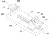
Fig. 1 is a schematic structural diagram of a moving assembly according to a first embodiment of the present invention.
Fig. 2 is a front view of the bottom plate of the first embodiment of the present invention.
Fig. 3 is a schematic structural view of a holding member according to a first embodiment of the present invention.
Fig. 4 is a schematic structural diagram of a rotating assembly according to a second embodiment of the present invention.
In the figure; 101-bottom plate, 102-sliding chute, 103-ball screw, 104-sliding plate, 105-main clamping block, 106-driving motor, 107-base, 108-main shaft, 109-rotating connecting rod, 110-clamping cylinder, 111-auxiliary clamping block, 112-guide rod, 201-rotating plate, 202-rotating clamping block, 203-pushing cylinder and 204-rotating motor.
Detailed Description
Reference will now be made in detail to the embodiments of the present invention, examples of which are illustrated in the accompanying drawings, which are described below by way of example with reference to the accompanying drawings, and which are intended to illustrate the present invention and are not to be construed as limiting the same.
The first embodiment of the present application is:
referring to fig. 1 to 3, wherein fig. 1 is a schematic structural view of a moving assembly, fig. 2 is a front view of a bottom plate, and fig. 3 is a schematic structural view of a clamping member, the present invention provides a crankshaft milling tool; the device comprises a bottom plate 101 and a moving assembly, wherein the bottom plate 101 is provided with a sliding chute 102, the moving assembly comprises a ball screw 103, a sliding plate 104, a main clamping block 105, a driving motor 106, a guide rod 112 and a clamping member, and the clamping member comprises a base 107, a main shaft 108, a rotating connecting rod 109, a clamping cylinder 110 and an auxiliary clamping block 111.
In the present embodiment, the bottom plate 101 has a slide groove 102, the ball screw 103 is rotatably connected to the bottom plate 101 and is located in the slide groove 102, the guide rod 112 is fixedly connected to the bottom plate 101 and is located on a side of the bottom plate 101 close to the ball screw 103, the sliding plate 104 is connected to the ball screw 103 and is slidably connected to the guide rod 112 and is located on a side of the ball screw 103 close to the guide rod 112, the main clamping block 105 is fixedly connected to the sliding plate 104 and is located on a side of the sliding plate 104 away from the ball screw 103, the driving motor 106 is connected to the bottom plate 101 and is connected to the ball screw 103 and is located on a side of the bottom plate 101 close to the ball screw 103, the clamping member is connected to the sliding plate 104, the rectangular slide groove 102 is located in the middle of the bottom plate 101, the ball screw 103 is mounted in the slide groove 102, the number of the guide rods 112 is two, the two guide rods 112 are respectively installed on the left and right sides of the ball screw 103, a screw nut matched with the ball screw 103 is connected to the bottom of the sliding plate 104, the screw nut at the bottom of the sliding plate 104 is connected to the ball screw 103, the two sides of the sliding plate 104 are respectively connected to the two guide rods 112 in a sliding manner, the main clamping block 105 is installed on the left side of the sliding plate 104, the clamping member is installed on the right side of the sliding plate 104, the rotation of the ball screw 103 is converted into the linear motion of the screw nut through the ball screw principle, the crankshaft can be clamped on the main clamping block 105 through the clamping member, so far, the driving motor 106 drives the ball screw 103 to rotate, and the sliding plate 104 can slide on the bottom plate 101 along the two guide rods 112 under the action of the screw nut and the ball screw 103 The position of the main clamping block 105 can be adjusted by sliding the sliding plate 104, crankshafts with different lengths can be clamped, and the application range of the tool is widened.
Wherein, the base 107 is fixedly connected with the sliding plate 104 and is positioned on one side of the sliding plate 104 close to the main clamping block 105; the main shaft 108 is rotatably connected to the base 107 and located on a side of the base 107 away from the sliding plate 104, the rotating link 109 is rotatably connected to the main shaft 108 and located on a side of the main shaft 108 away from the base 107, the clamping cylinder 110 is connected to the sliding plate 104 and rotatably connected to the rotating link 109 and located on a side of the sliding plate 104 close to the rotating link 109, the auxiliary clamp block 111 is fixedly connected to the main shaft 108 and located on a side of the main shaft 108 away from the base 107, the base 107 is mounted on a right side of the main clamp block 105, the main shaft 108 is rotatably mounted on an upper end of the base 107, the auxiliary clamp block 111 is mounted at a front end of the main shaft 108, one end of the rotating connecting rod 109 is rotatably installed at the central line position of the main shaft 108, the clamping cylinder 110 is installed below the main shaft 108, the type of the clamping cylinder 110 is SC20, the output end of the clamping cylinder 110 is rotatably connected with the other end of the rotating connecting rod 109, so that the main shaft 108 can be pushed away upwards by the clamping cylinder 110 through the rotary connection, the clamping cylinder 110 retracts, the rotating connecting rod 109 can pull the main shaft 108 to apply pressure downwards, a connecting shaft at one end of a crankshaft is placed on the main clamping block 105, and the main shaft 108 is pulled by the clamping cylinder 110 to clamp the auxiliary clamping block 111 at the upper end of the connecting shaft of the crankshaft, so that the crankshaft can be clamped quickly, the problem that a clamp needs to be fastened manually is solved, and the working efficiency is improved.
By using the crankshaft milling tool in the embodiment, the driving motor 106 drives the ball screw 103 to rotate, the sliding plate 104 can slide on the bottom plate 101 through a screw nut, the position of the main clamping block 105 can be adjusted through the sliding of the sliding plate 104, crankshafts with different lengths can be clamped, the main shaft 108 is pulled by the clamping cylinder 110 to clamp the auxiliary clamping block 111 at the upper end of the crankshaft connecting shaft, the crankshaft can be clamped quickly, the problem that the clamping tool needs to be fastened manually is solved, and the working efficiency is improved.
The second embodiment of the present application is:
on the basis of the first embodiment, please refer to fig. 4, fig. 4 is a schematic structural diagram of a rotating assembly, and the crankshaft milling tool of this embodiment further includes the rotating assembly, which includes a rotating plate 201, a rotating clamping block 202, a pushing cylinder 203, and a rotating motor 204.
For the present embodiment, the rotating assembly is connected to the bottom plate 101, and the rotating assembly can rotate the crankshaft.
Wherein, the rotating plate 201 is rotatably connected with the bottom plate 101 and is located on one side of the bottom plate 101 away from the sliding plate 104; the rotating clamping blocks 202 are connected with the rotating plate 201 in a sliding mode and located on one side, far away from the rotating plate 201, of the bottom plate 101, the pushing cylinders 203 are connected with the rotating clamping blocks 202 and located on one side, close to the rotating plate 201, of the rotating clamping blocks 202, the rotating motors 204 are connected with the bottom plate 101 and connected with the rotating plate 201 and located on one side, close to the rotating plate 201, of the bottom plate 101, side plates are arranged at the right end of the bottom plate 101, the rotating plates 201 are installed on the side plates in a rotating mode, the rotating motors 204 are connected with the side plates of the bottom plate 101, the output ends of the rotating motors 204 are connected with the rotating plate 201, the number of the rotating clamping blocks 202 is two, the two rotating clamping blocks 202 are symmetrically installed on two sides of the rotating plate 201 respectively, the pushing cylinders 203 are connected behind the two rotating clamping blocks 202, the model of the pushing cylinders 203 is SC20, the two pushing cylinders 203 push the two rotating clamping blocks 202 to clamp connecting shafts at the other end of a crankshaft respectively, the rotating clamping shafts of the rotating plate 201 are driven to rotate by the rotating motors 204, and the crankshaft is clamped on the rotating plate 201.
The crankshaft milling tool of the embodiment is used, the crankshaft can be clamped and clamped in the rotating plate 201 in a rotating mode, the crankshaft can be conveniently rotated by the tool equipment, and the crankshaft can be more conveniently machined.
While the above disclosure describes one or more preferred embodiments of the present invention, it is not intended to limit the scope of the claims to such embodiments, and one skilled in the art will understand that all or a portion of the processes performed in the above embodiments may be practiced without departing from the spirit and scope of the claims.
Claims (8)
1. A crankshaft milling tool comprises a bottom plate and is characterized in that,
the device also comprises a moving component;
the moving assembly comprises a ball screw, a guide rod, a sliding plate, a main clamping block, a driving motor and a clamping component, the bottom plate is provided with a sliding groove, the ball screw is rotatably connected with the bottom plate and is positioned in the sliding groove, the guide rod is fixedly connected with the bottom plate and is positioned on one side, close to the ball screw, of the bottom plate, the sliding plate is connected with the ball screw and is slidably connected with the guide rod and is positioned on one side, close to the guide rod, of the ball screw, the main clamping block is fixedly connected with the sliding plate and is positioned on one side, far away from the ball screw, of the sliding plate, the driving motor is connected with the bottom plate and is connected with the ball screw and is positioned on one side, close to the ball screw, of the bottom plate, and the clamping component is connected with the sliding plate.
2. The crankshaft milling tool of claim 1,
the clamping component comprises a base and a main shaft, the base is fixedly connected with the sliding plate and is positioned on one side, close to the main clamping block, of the sliding plate; the main shaft is rotatably connected with the base and is positioned on one side of the base, which is far away from the sliding plate.
3. The crankshaft milling tool of claim 2,
the clamping component further comprises a rotating connecting rod, the rotating connecting rod is rotatably connected with the main shaft and is positioned on one side, far away from the base, of the main shaft.
4. The crankshaft milling tool of claim 3,
the clamping member further comprises a clamping cylinder, the clamping cylinder is connected with the sliding plate, is rotatably connected with the rotating connecting rod and is positioned on one side, close to the rotating connecting rod, of the sliding plate.
5. The crankshaft milling tool of claim 2,
the clamping component further comprises an auxiliary clamping block, the auxiliary clamping block is fixedly connected with the main shaft and is positioned on one side, far away from the base, of the main shaft.
6. The crankshaft milling tool of claim 1,
the crankshaft milling tool further comprises a rotating assembly, and the rotating assembly is connected with the bottom plate.
7. The crankshaft milling tool of claim 6,
the rotating assembly comprises a rotating plate, a rotating clamping block and a pushing cylinder, and the rotating plate is rotatably connected with the bottom plate and is positioned on one side of the bottom plate, which is far away from the sliding plate; the rotating clamping block is connected with the rotating plate in a sliding mode and is positioned on one side, far away from the bottom plate, of the rotating plate; the pushing cylinder is connected with the rotating clamping block and is positioned on one side, close to the rotating plate, of the rotating clamping block.
8. The crankshaft milling tool of claim 7,
the rotating assembly further comprises a rotating motor, the rotating motor is connected with the bottom plate, connected with the rotating plate and located on one side, close to the rotating plate, of the bottom plate.
Priority Applications (1)
| Application Number | Priority Date | Filing Date | Title |
|---|---|---|---|
| CN202221765277.XU CN218136557U (en) | 2022-07-07 | 2022-07-07 | Crankshaft milling tool |
Applications Claiming Priority (1)
| Application Number | Priority Date | Filing Date | Title |
|---|---|---|---|
| CN202221765277.XU CN218136557U (en) | 2022-07-07 | 2022-07-07 | Crankshaft milling tool |
Publications (1)
| Publication Number | Publication Date |
|---|---|
| CN218136557U true CN218136557U (en) | 2022-12-27 |
Family
ID=84592812
Family Applications (1)
| Application Number | Title | Priority Date | Filing Date |
|---|---|---|---|
| CN202221765277.XU Active CN218136557U (en) | 2022-07-07 | 2022-07-07 | Crankshaft milling tool |
Country Status (1)
| Country | Link |
|---|---|
| CN (1) | CN218136557U (en) |
-
2022
- 2022-07-07 CN CN202221765277.XU patent/CN218136557U/en active Active
Similar Documents
| Publication | Publication Date | Title |
|---|---|---|
| CN203621979U (en) | Automatic clamping device for shaft workpieces | |
| CN219152674U (en) | Part clamping equipment for hardware tool machining | |
| CN206305813U (en) | A kind of workpiece linking clamping mechanism on lathe | |
| CN215617925U (en) | Workstation convenient to pincers worker uses | |
| CN223572945U (en) | An adjustable-pitch part clamping device | |
| CN212683233U (en) | Fixed mechanical fixture for machining | |
| CN220273945U (en) | Clamp for circuit board processing | |
| CN218340753U (en) | Special punch device for pipe machining | |
| CN2241042Y (en) | Electric plain vice | |
| CN219684589U (en) | Automatic bar positioning and clamping device | |
| CN216263678U (en) | Vertical and horizontal dual-purpose milling machine tool | |
| CN217619101U (en) | A from centering anchor clamps for new forms of energy trades power station | |
| CN219902095U (en) | Workpiece taking jig | |
| CN220943572U (en) | Wire-electrode cutting presss from both sides tight frock | |
| CN2875704Y (en) | Automatic fast clamping tong device | |
| CN219233761U (en) | Automatic workpiece fixing device for punching machine | |
| CN220006842U (en) | Centering clamp for gear shaft of electric automobile transmission | |
| CN222359691U (en) | A high-strength lathe claw | |
| CN219358755U (en) | Clamping and positioning device of radial drilling machine | |
| CN222429992U (en) | A precision machined automatic centering flat-nose pliers | |
| CN221019746U (en) | Nodular cast iron section bar centre gripping frock | |
| CN223955757U (en) | Travel switch detects frock | |
| CN215036726U (en) | Multi-station clamping equipment | |
| CN222472215U (en) | An automatic clamping device for hydraulic cylinder processing | |
| CN223763184U (en) | A rotating device for manufacturing mechanical parts |
Legal Events
| Date | Code | Title | Description |
|---|---|---|---|
| GR01 | Patent grant | ||
| GR01 | Patent grant |