CN218123495U - Battery core laminating machine - Google Patents
Battery core laminating machine Download PDFInfo
- Publication number
- CN218123495U CN218123495U CN202221651889.6U CN202221651889U CN218123495U CN 218123495 U CN218123495 U CN 218123495U CN 202221651889 U CN202221651889 U CN 202221651889U CN 218123495 U CN218123495 U CN 218123495U
- Authority
- CN
- China
- Prior art keywords
- lamination
- platform
- support
- film
- film covering
- Prior art date
- Legal status (The legal status is an assumption and is not a legal conclusion. Google has not performed a legal analysis and makes no representation as to the accuracy of the status listed.)
- Active
Links
- 238000010030 laminating Methods 0.000 title claims abstract description 65
- 238000003475 lamination Methods 0.000 claims abstract description 229
- 230000007246 mechanism Effects 0.000 claims abstract description 154
- 238000009434 installation Methods 0.000 claims abstract description 11
- 239000012528 membrane Substances 0.000 claims abstract description 10
- 230000005540 biological transmission Effects 0.000 claims description 70
- 230000006835 compression Effects 0.000 claims description 37
- 238000007906 compression Methods 0.000 claims description 37
- 239000007888 film coating Substances 0.000 claims description 35
- 238000009501 film coating Methods 0.000 claims description 35
- 210000002489 tectorial membrane Anatomy 0.000 abstract description 16
- 238000004519 manufacturing process Methods 0.000 abstract description 10
- 239000000463 material Substances 0.000 abstract description 5
- 229910052744 lithium Inorganic materials 0.000 description 10
- 238000000034 method Methods 0.000 description 10
- WHXSMMKQMYFTQS-UHFFFAOYSA-N Lithium Chemical compound [Li] WHXSMMKQMYFTQS-UHFFFAOYSA-N 0.000 description 9
- HBBGRARXTFLTSG-UHFFFAOYSA-N Lithium ion Chemical compound [Li+] HBBGRARXTFLTSG-UHFFFAOYSA-N 0.000 description 8
- 229910001416 lithium ion Inorganic materials 0.000 description 8
- 238000013461 design Methods 0.000 description 5
- 230000010354 integration Effects 0.000 description 5
- 239000011248 coating agent Substances 0.000 description 2
- 238000000576 coating method Methods 0.000 description 2
- 239000000203 mixture Substances 0.000 description 2
- 229910000733 Li alloy Inorganic materials 0.000 description 1
- 230000009286 beneficial effect Effects 0.000 description 1
- 239000008358 core component Substances 0.000 description 1
- 230000007547 defect Effects 0.000 description 1
- 238000011161 development Methods 0.000 description 1
- 238000010586 diagram Methods 0.000 description 1
- 230000008676 import Effects 0.000 description 1
- 239000001989 lithium alloy Substances 0.000 description 1
- 238000012423 maintenance Methods 0.000 description 1
- 229920000642 polymer Polymers 0.000 description 1
- 238000012827 research and development Methods 0.000 description 1
- 238000001179 sorption measurement Methods 0.000 description 1
Images






Classifications
-
- Y—GENERAL TAGGING OF NEW TECHNOLOGICAL DEVELOPMENTS; GENERAL TAGGING OF CROSS-SECTIONAL TECHNOLOGIES SPANNING OVER SEVERAL SECTIONS OF THE IPC; TECHNICAL SUBJECTS COVERED BY FORMER USPC CROSS-REFERENCE ART COLLECTIONS [XRACs] AND DIGESTS
- Y02—TECHNOLOGIES OR APPLICATIONS FOR MITIGATION OR ADAPTATION AGAINST CLIMATE CHANGE
- Y02E—REDUCTION OF GREENHOUSE GAS [GHG] EMISSIONS, RELATED TO ENERGY GENERATION, TRANSMISSION OR DISTRIBUTION
- Y02E60/00—Enabling technologies; Technologies with a potential or indirect contribution to GHG emissions mitigation
- Y02E60/10—Energy storage using batteries
-
- Y—GENERAL TAGGING OF NEW TECHNOLOGICAL DEVELOPMENTS; GENERAL TAGGING OF CROSS-SECTIONAL TECHNOLOGIES SPANNING OVER SEVERAL SECTIONS OF THE IPC; TECHNICAL SUBJECTS COVERED BY FORMER USPC CROSS-REFERENCE ART COLLECTIONS [XRACs] AND DIGESTS
- Y02—TECHNOLOGIES OR APPLICATIONS FOR MITIGATION OR ADAPTATION AGAINST CLIMATE CHANGE
- Y02P—CLIMATE CHANGE MITIGATION TECHNOLOGIES IN THE PRODUCTION OR PROCESSING OF GOODS
- Y02P70/00—Climate change mitigation technologies in the production process for final industrial or consumer products
- Y02P70/50—Manufacturing or production processes characterised by the final manufactured product
Landscapes
- Secondary Cells (AREA)
Abstract
The utility model discloses a battery cell laminating machine, which comprises a diaphragm unreeling part, a pole piece conveying part, a laminating film covering part and a platform part, wherein the platform part comprises a deviation rectifying platform, a laminating platform and a deviation rectifying platform which are horizontally arranged at intervals; the membrane unreeling part is arranged above the platform part; the pole piece conveying part is arranged on the outer side of the deviation rectifying platform; the lamination laminating part is arranged between the platform part and the diaphragm unreeling part and comprises a driving mechanism, a laminating mechanism and at least two groups of lamination mechanisms, wherein the driving mechanism is horizontally arranged, and the laminating mechanism is movably arranged on the driving mechanism. The utility model discloses the function of rectifying before possessing the lamination promotes the lamination quality, and is integrated in an organic whole with multiunit lamination mechanism and tectorial membrane mechanism, realizes through one set of power drive that the pole piece is automatic to be got the material, rectifies, lamination and tectorial membrane, and multimachine constructs in coordination, effectively reduces the station standby, promotes lamination efficiency, and realization structure simplifies, saves installation space, reduces and maintains manufacturing cost.
Description
Technical Field
The utility model relates to a lithium ion power battery makes the field, indicates a battery core lamination machine who is used for automatic battery core lamination to make very much.
Background
Lithium battery refers to a battery containing Lithium including metallic Lithium, lithium alloy and Lithium ion, lithium polymer in electrochemical system. Lithium batteries can be broadly classified into two types: lithium metal batteries and lithium ion batteries. A lithium battery is a type of rechargeable battery that mainly operates by movement of lithium ions between a positive electrode and a negative electrode. Batteries using a material containing lithium as an electrode are typical of modern high-performance batteries. With the development of new energy greatly promoted by the state, the demand of various industries on lithium ion power batteries is increasing day by day, and a battery cell in a composition structure of the lithium ion power battery is a core component of the lithium ion power battery, and the battery cell is generally formed by mutually overlapping positive and negative pole pieces in a staggered manner. The battery core composition structure comprises a plurality of positive and negative pole pieces which are staggered and overlapped up and down, and the positive and negative pole pieces are isolated and insulated by a diaphragm. At present, lithium battery equipment with more advanced domestic technology is mainly mastered by foreign equipment suppliers, and domestic high-end lithium battery lamination equipment mainly depends on import at present.
The electric core of the lithium ion battery is generally formed by overlapping positive and negative pole pieces in a staggered manner, and an insulating diaphragm is required to be inserted between the positive and negative pole pieces. The existing battery core manufacturing process comprises two modes of strip lamination and single lamination according to different diaphragm inserting processes, namely continuous diaphragms and single diaphragm lamination are adopted during lamination. For the Z-lamination process of the strip-shaped lamination process, positive and negative pole pieces are alternately placed on a lamination platform during lamination, a strip-shaped diaphragm is circularly pulled back and forth above the lamination platform, the surface of the positive pole piece or the surface of the negative pole piece is covered after the positive pole piece or the negative pole piece is laminated, and then the diaphragm is cut.
Aiming at the Z-stacking process, the following technical problems exist: 1. the existing Z-stacking process directly takes out pole pieces through a mechanical moving arm and then stacks the pole pieces on a stacking platform, and position errors exist in the pole pieces in the adsorption moving process, so that the stacking quality is influenced. 2. The existing Z-stacking process adopts single-mechanism stacking, requires taking pole pieces, moving the pole pieces and stacking through a plurality of stacking mechanisms, and has the disadvantages of complex design, high difficulty in subsequent maintenance of the mechanism and high manufacturing cost.
SUMMERY OF THE UTILITY MODEL
The to-be-solved technical problem of the utility model is not enough to above-mentioned prior art, a function of rectifying before possessing the lamination is provided, effectively promote the lamination quality, and with multiunit lamination mechanism and tectorial membrane mechanism integration in an organic whole, through one set of power drive, realized that the pole piece is automatic to be got the material, rectify, lamination and tectorial membrane, multiunit mechanism is in coordination, effectively reduces the station standby, promotes lamination efficiency to simplified the structure, saved installation space, reduced manufacturing cost's electric core lamination machine.
The utility model adopts the following technical scheme: a battery core laminating machine comprises a diaphragm unreeling part, a pole piece conveying part, a laminating film covering part and a platform part, wherein,
the platform part comprises a lamination platform and two deviation rectifying platforms which are horizontally arranged on two sides of the lamination platform at intervals;
the membrane unreeling part is arranged above the platform part and guides the strip-shaped membrane coiled in the membrane unreeling part downwards;
the pole piece conveying part is arranged on the outer side of the deviation rectifying platform and conveys the sheet pole pieces horizontally and linearly towards the direction of the lamination platform;
the lamination film coating part is arranged between the platform part and the diaphragm unreeling part and comprises a horizontally arranged driving mechanism, a film coating mechanism movably arranged on the driving mechanism and at least two groups of lamination mechanisms;
the strip-shaped diaphragm in the diaphragm unwinding part is inserted into the film laminating mechanism, and the film laminating mechanism drives the diaphragm to move linearly back and forth above the lamination platform so as to laminate the diaphragm on the lamination platform along a Z-shaped path;
the at least two groups of lamination mechanisms are correspondingly arranged on two sides of the laminating mechanism, the lamination mechanisms positioned on two sides of the lamination platform alternately move the pole pieces from the pole piece conveying part to the deviation rectifying platform, and move and laminate the pole pieces with the position rectified on the deviation rectifying platform to the lamination platform.
Preferably, the film covering mechanism and at least two groups of lamination mechanisms are connected to the output end of the driving mechanism and driven by the driving mechanism to independently move linearly.
Preferably, the lamination mechanisms comprise four groups, every two lamination mechanisms are respectively arranged on two sides of the film covering mechanism in one group, and in the two groups of lamination mechanisms positioned on the same side of the film covering mechanism, one group of lamination mechanisms takes out the positive plate or the negative plate from the pole piece conveying part on the side and moves the positive plate or the negative plate to the deviation rectifying platform; and the other group of lamination mechanisms takes out the positive plate or the negative plate from the deviation rectifying platform and moves and overlaps the positive plate or the negative plate to the overlapping platform.
Preferably, the driving mechanism is arranged on a support, the support is of a U-shaped frame structure, and the middle of the support is provided with an installation groove body; the driving mechanism is horizontally arranged in the mounting groove body.
Preferably, the driving mechanism comprises a linear module and a driving sliding seat, wherein the linear module is horizontally arranged in the mounting groove body; the driving sliding seats comprise at least two driving sliding seats, and the at least two driving sliding seats are connected to the linear module in a sliding manner along the linear direction and are connected with the output end of the linear module; the lamination mechanism and the film laminating mechanism are arranged on each driving sliding seat.
Preferably, the lamination mechanism comprises a lamination support, a transmission assembly, a lamination support and a lamination suction seat, wherein the lamination support is an L-shaped frame body and comprises a horizontal support plate and a vertical support plate which are vertically connected with each other, and the horizontal support plate is connected to the driving sliding seat; the transmission assembly is arranged on the laminated support and outputs power along the vertical direction; the lamination support is slidably connected to the side part of the vertical support plate of the lamination support and is connected with the output end of the transmission assembly; the lamination suction seat is arranged on the lamination support, and the bottom of the lamination suction seat is provided with a vacuum suction hole so as to adsorb the pole piece.
Preferably, the transmission assembly comprises a lamination motor, a lamination transmission gear, a lamination transmission rack and a lamination sliding seat, wherein the lamination motor is horizontally arranged on a horizontal support plate of the lamination support, and the lamination transmission gear is sleeved on an output shaft of the lamination motor; the lamination sliding seat is connected to the side wall of the vertical support plate of the lamination support in a sliding manner in the vertical direction; the lamination transmission rack is vertically connected to the lamination sliding seat and meshed with the lamination transmission gear, and the lamination transmission rack is driven to drive the lamination sliding seat to move up and down when the lamination transmission gear rotates; the lamination support is connected to the lamination slide.
Preferably, the film covering mechanism comprises a film covering bracket, a film covering transmission assembly, a film covering support, a guide roller and a press roller assembly, wherein the film covering bracket is an L-shaped bracket body and comprises a horizontal support plate and a vertical support plate which are vertically connected with each other, and the horizontal support plate is connected to the driving sliding seat; the film covering transmission assembly is arranged on the film covering bracket, and the output end of the film covering transmission assembly extends towards the vertical direction; the film covering support is connected to the side part of a vertical support plate of the film covering bracket in a sliding manner along the vertical direction and is connected with the output end of the film covering transmission assembly; the two guide rollers are arranged on the film covering bracket in parallel at intervals and are rotatably connected with the film covering bracket, and the strip-shaped diaphragm penetrates through a gap space between the two guide rollers from top to bottom; above-mentioned compression roller assembly sets up in the deflector roll below, and compression roller assembly compresses tightly banded diaphragm from both sides.
Preferably, the film covering transmission assembly comprises a film covering motor, a film covering transmission gear, a film covering transmission rack and a film covering sliding seat, wherein the film covering motor is horizontally arranged on a horizontal support plate of the film covering bracket, and the film covering transmission gear is sleeved on an output shaft of the film covering motor; the film covering slide seat is slidably arranged on the side wall of the vertical support plate of the film covering bracket along the vertical direction; the film coating transmission rack is vertically arranged on the film coating sliding seat and is meshed and connected with the film coating transmission gear, and when the film coating transmission gear rotates, the film coating transmission rack is driven to drive the film coating sliding seat to move up and down; the film covering support is connected to the film covering sliding seat.
Preferably, the compression roller assembly comprises two compression roller support plates, a compression roller cylinder and a compression roller, wherein the two compression roller support plates are respectively and rotatably connected to two sides of the film covering support and are positioned below the guide roller; the two compression roller cylinders are respectively arranged on the film covering support corresponding to the compression roller support plate and drive the compression roller support plate to rotate; the two compression rollers are respectively and rotatably connected to the lower parts of the two compression roller support plates, and the strip-shaped diaphragm penetrates through a gap space between the two compression rollers from top to bottom and is compressed by the two compression rollers.
The beneficial effects of the utility model reside in that:
the utility model discloses defect and not enough independent research and development to prior art exist have designed one kind possess the lamination before function of rectifying, effectively promote the lamination quality, and with multiunit lamination mechanism and tectorial membrane mechanism integration in an organic whole, through one set of power drive, realized that the pole piece is automatic to be got the material, rectify, lamination and tectorial membrane, simplified the structure effectively, save installation space, reduced manufacturing cost's electric core lamination machine.
The utility model discloses compare in traditional Z and folded technology, the left and right sides of lamination platform has set up the platform of rectifying a deviation in the interval respectively, rectifies a deviation through the platform of rectifying a deviation earlier before the pole piece coincide to the promotion of lamination quality has been realized. Meanwhile, due to the fact that a deviation rectifying work station is additionally arranged, according to the traditional Z-stacking process, the steps of transferring the pole piece to a deviation rectifying station, rectifying the deviation of the pole piece and transferring the pole piece from the deviation rectifying station are added, and the three steps consume a certain production time, so that the whole lamination efficiency is reduced. Based on above problem, through independently researching and developing the design, the utility model discloses regard sharp module as whole actuating mechanism, support through U type frame structure is as the installation carrier, with sharp module horizontal installation in the mounting groove of support internal, set up four lamination mechanism of group and a set of tectorial membrane mechanism on sharp module along the sharp direction interval simultaneously and can increase and decrease according to actual production process needs in lamination mechanism or tectorial membrane mechanism's quantity, wherein lamination mechanism is located the middle part, two liang of a set of two sets of the lamination mechanism of four group set up in tectorial membrane mechanism's both sides, the lamination mechanism of one side is used for coincide positive plate or negative pole piece, the lamination mechanism of opposite side is used for coincide negative pole piece or positive plate. When the pole piece conveying parts positioned at the outer sides of the two deviation rectifying platforms convey the positive and negative pole pieces of a single piece horizontally and linearly towards the direction of the laminating platform through a conveyor belt or other mechanisms, the laminating mechanisms positioned at the same side of the film coating mechanism take the pole pieces out of the pole piece conveying parts and place the pole pieces on the deviation rectifying platforms, and the laminating mechanisms positioned at the inner sides of the laminating platforms take the pole pieces after deviation rectification out of the deviation rectifying platforms and laminate the pole pieces onto the laminating platforms; the two groups of lamination mechanisms positioned at the two sides of the laminating mechanism alternately perform the actions, so that the positive plates and the negative plates are alternately laminated on the lamination platform respectively. The laminating mechanism is arranged at the middle position, after clamping the strip diaphragm inserted into the laminating mechanism from top to bottom, the strip diaphragm is horizontally pulled out from left to right along the laminating platform and is coated on the pole piece through the driving of the linear module, namely after the laminating mechanism horizontally coats the strip diaphragm on the laminating platform along one direction, the pole piece at one side is laminated on the diaphragm of the laminating platform by the laminating mechanism at one side, the laminating mechanism returns along the other direction, the strip diaphragm is horizontally and reversely coated on the laminated pole piece, and then the pole piece at the other side is laminated on the diaphragm by the laminating mechanism at the other side; and repeating the alternating circulation in such a way until the lamination of the battery cells is completed. Through above design, not only with multiunit lamination mechanism and tectorial membrane mechanism integration in an organic whole, utilize one set of sharp module drive, realized the structure simplification, simultaneously, utilize outside lamination mechanism to get the time of pole piece, inboard lamination mechanism accomplishes and gets pole piece and lamination from rectifying on the platform, carries out a plurality of technological actions simultaneously promptly in same time quantum, has avoided station stand-by time to consume, has promoted lamination efficiency effectively.
Drawings
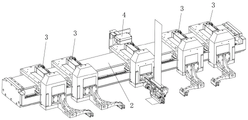
Fig. 1 is a schematic structural diagram of the present invention.
Fig. 2 is a schematic view of a three-dimensional structure of the present invention.
Fig. 3 is a second schematic perspective view of the present invention.
Fig. 4 is one of the schematic three-dimensional structures of the lamination film covering part and the platform part of the present invention.
Fig. 5 is a second schematic perspective view of the lamination film covering portion and the platform portion of the present invention.
Fig. 6 is a third schematic view of a three-dimensional structure of the lamination film covering part and the platform part of the present invention.
Fig. 7 is one of the schematic three-dimensional structures of the lamination film covering part of the present invention.
Fig. 8 is a second schematic perspective view of the lamination film covering portion of the present invention.
Fig. 9 is a schematic perspective view of the lamination mechanism of the present invention.
Fig. 10 is a schematic perspective view of the lamination mechanism of the present invention.
Fig. 11 is a schematic perspective view of the film covering mechanism of the present invention.
Fig. 12 is a schematic perspective view of the driving mechanism of the present invention.
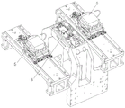
Fig. 13 is a schematic perspective view of the lamination platform according to the present invention.
Fig. 14 is a second perspective view of the lamination platform according to the present invention.
Detailed Description
The invention will be further described with reference to the accompanying drawings:
as shown in fig. 1 to 14, the technical solution adopted by the present invention is as follows: a battery core laminating machine comprises a diaphragm unreeling part, a pole piece conveying part, a laminating film covering part and a platform part, wherein,
the platform part comprises a lamination platform and two deviation rectifying platforms which are horizontally arranged on two sides of the lamination platform at intervals;
the membrane unreeling part is arranged above the platform part and guides the strip-shaped membrane coiled in the membrane unreeling part downwards;
the pole piece conveying part is arranged on the outer side of the deviation rectifying platform and conveys the sheet pole pieces horizontally and linearly towards the direction of the lamination platform;
the lamination film coating part is arranged between the platform part and the diaphragm unreeling part and comprises a horizontally arranged driving mechanism, a film coating mechanism movably arranged on the driving mechanism and at least two groups of lamination mechanisms;
the strip-shaped diaphragm in the diaphragm unwinding part is inserted into the film laminating mechanism, and the film laminating mechanism drives the diaphragm to linearly move back and forth above the lamination platform so as to laminate the diaphragm on the lamination platform along a Z-shaped path;
the at least two groups of lamination mechanisms are correspondingly arranged on two sides of the laminating mechanism, the lamination mechanisms positioned on two sides of the lamination platform alternately move the pole pieces from the pole piece conveying part to the deviation rectifying platform, and move and laminate the pole pieces with the position rectified on the deviation rectifying platform to the lamination platform.
The film covering mechanism and at least two groups of lamination mechanisms are connected to the output end of the driving mechanism and driven by the driving mechanism to independently move linearly.
The lamination mechanisms 3 comprise four groups, every two lamination mechanisms 3 are respectively arranged on two sides of the film laminating mechanism 4, and in the two groups of lamination mechanisms 3 positioned on the same side of the film laminating mechanism 4, one group of lamination mechanisms 3 takes out the positive plate or the negative plate from the pole piece conveying part 8 on the side and moves the positive plate or the negative plate to the deviation rectifying platform 5; and the other group of lamination mechanisms 3 takes out the positive plate or the negative plate from the deviation rectifying platform 5 and carries and overlaps the positive plate or the negative plate to the overlapping platform 6.
The driving mechanism 2 is arranged on the support 1, the support 1 is of a U-shaped frame body structure, and the middle part of the support is provided with an installation groove body; the driving mechanism 2 is horizontally arranged in the mounting groove body.
The driving mechanism 2 comprises a linear module 21 and a driving slide 22, wherein the linear module 21 is horizontally arranged in the mounting groove body; the driving sliders 22 comprise at least two, and the at least two driving sliders 22 are slidably connected to the linear module 21 along the linear direction and connected to the output end of the linear module 21; the lamination mechanism and the film coating mechanism are disposed on the respective driving sliders 22.
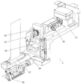
The lamination mechanism 3 comprises a lamination support 31, a transmission assembly, a lamination support 36 and a lamination suction seat 37, wherein the lamination support 31 is an L-shaped frame body and comprises a horizontal support plate and a vertical support plate which are vertically connected with each other, and the horizontal support plate is connected to the driving slide seat 22; the transmission assembly is arranged on the lamination support 31 and outputs power along the vertical direction; the lamination support 36 is slidably connected to the side of the vertical plate of the lamination holder 31 and is connected to the output end of the transmission assembly; the lamination suction seat 37 is arranged on the lamination support 36, and vacuum suction holes are distributed at the bottom of the lamination suction seat 37 so as to adsorb the pole pieces.
The transmission assembly comprises a lamination motor 32, a lamination transmission gear 33, a lamination transmission rack 34 and a lamination sliding seat 35, wherein the lamination motor 32 is horizontally arranged on a horizontal support plate of the lamination support 31, and the lamination transmission gear 33 is sleeved on an output shaft of the lamination motor 32; the lamination sliding seat 35 is connected to the side wall of the vertical support plate of the lamination support 31 in a sliding manner in the vertical direction; the lamination transmission rack 34 is vertically connected to the lamination sliding seat 35 and is meshed with the lamination transmission gear 33, and the lamination transmission rack 34 is driven to drive the lamination sliding seat 35 to move up and down when the lamination transmission gear 33 rotates; the lamination shoe 36 is attached to the lamination slide 35.
The film covering mechanism 4 comprises a film covering bracket 41, a film covering transmission assembly, a film covering support 46, a guide roller 47 and a compression roller assembly, wherein the film covering bracket 41 is an L-shaped frame body and comprises a horizontal support plate and a vertical support plate which are vertically connected with each other, and the horizontal support plate is connected to the driving slide seat 22; the film covering transmission assembly is arranged on the film covering bracket 41, and the output end of the film covering transmission assembly extends towards the vertical direction; the film coating support 46 is connected to the side of the vertical support plate of the film coating support 41 in a sliding manner along the vertical direction and is connected with the output end of the film coating transmission assembly; the two guide rollers 47 are arranged on the covered film bracket 41 in parallel at intervals and are rotatably connected with the covered film bracket 41, and the strip-shaped diaphragm passes through a gap space between the two guide rollers 47 from top to bottom; the above-mentioned roller assembly sets up in deflector roll 47 below, and roller assembly compresses tightly banded diaphragm from both sides.
The film covering transmission assembly comprises a film covering motor 42, a film covering transmission gear 43, a film covering transmission rack 44 and a film covering sliding seat 45, wherein the film covering motor 42 is horizontally arranged on a horizontal support plate of the film covering bracket 41, and the film covering transmission gear 43 is sleeved on an output shaft of the film covering motor 42; the film-coating slide seat 45 is slidably arranged on the side wall of the vertical support plate of the film-coating bracket 41 along the vertical direction; the film coating transmission rack 44 is vertically arranged on the film coating sliding seat 45 and is meshed with the film coating transmission gear 43, and when the film coating transmission gear 43 rotates, the film coating transmission rack 44 is driven to drive the film coating sliding seat 45 to move up and down; the coating holder 46 is connected to the coating slide 45.
The compression roller assembly comprises two compression roller support plates, a compression roller cylinder and a compression roller 48, wherein the two compression roller support plates are respectively and rotatably connected to two sides of the laminating support 46 and are positioned below the guide roller 47; the two compression roller cylinders are respectively arranged on the film covering support 46 corresponding to the compression roller support plates and drive the compression roller support plates to rotate; the two press rollers 48 are rotatably connected to the lower portions of the two press roller support plates respectively, and the belt-shaped diaphragm penetrates through a gap space between the two press rollers 48 from top to bottom and is pressed tightly by the two press rollers 48.
Further, the utility model discloses a function of rectifying before possessing the lamination effectively promotes the lamination quality, and with multiunit lamination mechanism and tectorial membrane mechanism integration in an organic whole, through one set of power drive, realized that the pole piece is automatic to be got the material, rectify, lamination and tectorial membrane, simplified the structure effectively, saved installation space, reduced manufacturing cost's electric core lamination machine. The utility model discloses compare in traditional Z and fold technology, the left and right sides of lamination platform has set up the platform of rectifying in the interval respectively, rectifies through the platform of rectifying before the pole piece coincide to the promotion of lamination quality has been realized. Simultaneously, owing to increased the worker station of rectifying, according to traditional Z pile technology, increased the pole piece and shifted to the station of rectifying, the pole piece rectifies a deviation, the pole piece shifts out from the station of rectifying a deviation, three process, because above three process can consume certain production duration, therefore can lead to whole lamination efficiency to descend. Based on above problem, through independently researching and developing the design, the utility model discloses regard sharp module as whole actuating mechanism, support through U type frame structure is as the installation carrier, with sharp module horizontal installation in the mounting groove of support internal, set up four lamination mechanism of group and a set of tectorial membrane mechanism on sharp module along the sharp direction interval simultaneously and can increase and decrease according to actual production process needs in lamination mechanism or tectorial membrane mechanism's quantity, wherein lamination mechanism is located the middle part, two liang of a set of two sets of the lamination mechanism of four group set up in tectorial membrane mechanism's both sides, the lamination mechanism of one side is used for coincide positive plate or negative pole piece, the lamination mechanism of opposite side is used for coincide negative pole piece or positive plate. When the pole piece conveying parts positioned at the outer sides of the two deviation rectifying platforms convey the positive and negative pole pieces of a single piece horizontally and linearly towards the direction of the laminating platform through a conveyor belt or other mechanisms, the laminating mechanisms positioned at the same side of the film coating mechanism take the pole pieces out of the pole piece conveying parts and place the pole pieces on the deviation rectifying platforms, and the laminating mechanisms positioned at the inner sides of the laminating platforms take the pole pieces after deviation rectification out of the deviation rectifying platforms and laminate the pole pieces onto the laminating platforms; the two groups of lamination mechanisms positioned at the two sides of the laminating mechanism alternately perform the actions, so that the positive plates and the negative plates are alternately laminated on the lamination platform respectively. The laminating mechanism is arranged at the middle position, after clamping the strip diaphragm inserted into the laminating mechanism from top to bottom, the strip diaphragm is horizontally pulled out from left to right along the laminating platform and is coated on the pole piece through the driving of the linear module, namely after the laminating mechanism horizontally coats the strip diaphragm on the laminating platform along one direction, the pole piece at one side is laminated on the diaphragm of the laminating platform by the laminating mechanism at one side, the laminating mechanism returns along the other direction, the strip diaphragm is horizontally and reversely coated on the laminated pole piece, and then the pole piece at the other side is laminated on the diaphragm by the laminating mechanism at the other side; and repeating the alternating circulation in such a way until the lamination of the battery cells is completed. Through above design, not only with multiunit lamination mechanism and tectorial membrane mechanism integration in an organic whole, utilize one set of sharp module drive, realized the structure simplification, simultaneously, utilize outside lamination mechanism to get the time of pole piece, inboard lamination mechanism accomplishes and gets pole piece and lamination from rectifying on the platform, carries out a plurality of technological actions simultaneously promptly in same time quantum, has avoided station stand-by time to consume, has promoted lamination efficiency effectively.
The embodiments of the present invention are only for describing the specific embodiments thereof, and are not intended to limit the scope of the protection thereof. The present invention is not limited to the above embodiments, but can be modified in various ways without departing from the scope of the present invention.
Claims (10)
1. The utility model provides a battery core lamination machine which characterized in that: comprises a diaphragm unreeling part, a pole piece transmission part, a lamination film covering part and a platform part, wherein,
the platform part comprises a lamination platform and two deviation rectifying platforms which are horizontally arranged on two sides of the lamination platform at intervals;
the membrane unreeling part is arranged above the platform part and guides the strip-shaped membrane coiled in the membrane unreeling part downwards;
the pole piece conveying part is arranged on the outer side of the deviation rectifying platform and conveys the sheet pole pieces horizontally and linearly towards the direction of the lamination platform;
the lamination film coating part is arranged between the platform part and the diaphragm unreeling part and comprises a horizontally arranged driving mechanism, a film coating mechanism movably arranged on the driving mechanism and at least two groups of lamination mechanisms;
the strip-shaped diaphragm in the diaphragm unwinding part is inserted into the film laminating mechanism, and the film laminating mechanism drives the diaphragm to linearly move back and forth above the lamination platform so as to laminate the diaphragm on the lamination platform along a Z-shaped path;
the at least two groups of lamination mechanisms are correspondingly arranged on two sides of the laminating mechanism, the lamination mechanisms positioned on two sides of the lamination platform alternately move the pole pieces from the pole piece conveying part to the deviation rectifying platform, and move and laminate the pole pieces with the position rectified on the deviation rectifying platform to the lamination platform.
2. The cell lamination machine of claim 1, wherein: the film covering mechanism and at least two groups of lamination mechanisms are connected to the output end of the driving mechanism and driven by the driving mechanism to independently move linearly.
3. The cell lamination machine of claim 1, wherein: the lamination mechanisms (3) comprise four groups, every two lamination mechanisms (3) are respectively arranged on two sides of the film laminating mechanism (4) in one group, the two groups of lamination mechanisms (3) are positioned on the same side of the film laminating mechanism (4), and the group of lamination mechanisms (3) take out positive plates or negative plates from the pole piece conveying part (8) on the side and move the positive plates or the negative plates to the deviation rectifying platform (5); and the other group of lamination mechanisms (3) takes out the positive plate or the negative plate from the deviation rectifying platform (5) and moves and laminates the positive plate or the negative plate to the laminating platform (6).
4. The cell lamination machine of claim 1, wherein: the driving mechanism (2) is arranged on the support (1), the support (1) is of a U-shaped frame structure, and the middle part of the support is provided with an installation groove body; the driving mechanism (2) is horizontally arranged in the mounting groove body.
5. The cell lamination machine of claim 4, wherein: the driving mechanism (2) comprises a linear module (21) and a driving sliding seat (22), wherein the linear module (21) is horizontally arranged in the mounting groove body; the driving sliding seats (22) comprise at least two, and the at least two driving sliding seats (22) are connected to the linear module (21) in a sliding manner along the linear direction and are connected with the output end of the linear module (21); the lamination mechanism and the film coating mechanism are arranged on each driving sliding seat (22).
6. The cell lamination machine of claim 5, wherein: the lamination mechanism (3) comprises a lamination support (31), a transmission assembly, a lamination support (36) and a lamination suction seat (37), wherein the lamination support (31) is an L-shaped frame body and comprises a horizontal support plate and a vertical support plate which are vertically connected with each other, and the horizontal support plate is connected to the driving sliding seat (22); the transmission assembly is arranged on the lamination support (31) and outputs power along the vertical direction; the lamination support (36) is connected to the side part of the vertical support plate of the lamination support (31) in a sliding way and is connected with the output end of the transmission assembly; the lamination suction seat (37) is arranged on the lamination support seat (36), and vacuum suction holes are distributed at the bottom of the lamination suction seat (37) so as to adsorb the pole piece.
7. The cell lamination machine of claim 6, wherein: the transmission assembly comprises a lamination motor (32), a lamination transmission gear (33), a lamination transmission rack (34) and a lamination sliding seat (35), wherein the lamination motor (32) is horizontally arranged on a horizontal support plate of the lamination support (31), and the lamination transmission gear (33) is sleeved on an output shaft of the lamination motor (32); the lamination sliding seat (35) is connected to the side wall of the vertical support plate of the lamination support (31) in a sliding manner in the vertical direction; the lamination transmission rack (34) is vertically connected to the lamination sliding seat (35) and is meshed with the lamination transmission gear (33), and the lamination transmission gear (33) drives the lamination transmission rack (34) to drive the lamination sliding seat (35) to move up and down when rotating; the lamination support (36) is connected to the lamination slide (35).
8. The cell lamination machine of claim 5, wherein: the film laminating mechanism (4) comprises a film laminating support (41), a film laminating transmission assembly, a film laminating support (46), a guide roller (47) and a press roller assembly, wherein the film laminating support (41) is an L-shaped support body and comprises a horizontal support plate and a vertical support plate which are vertically connected with each other, and the horizontal support plate is connected to the driving sliding seat (22); the film covering transmission assembly is arranged on the film covering bracket (41), and the output end of the film covering transmission assembly extends towards the vertical direction; the film covering support (46) is connected to the side part of a vertical support plate of the film covering support (41) in a sliding manner along the vertical direction and is connected with the output end of the film covering transmission assembly; the two guide rollers (47) are arranged on the covered film bracket (41) in parallel at intervals and are rotatably connected with the covered film bracket (41), and the strip-shaped diaphragm passes through a gap space between the two guide rollers (47) from top to bottom; the compression roller assembly is arranged below the guide roller (47), and the compression roller assembly compresses the strip-shaped diaphragm from two sides.
9. The cell lamination machine of claim 8, wherein: the film covering transmission assembly comprises a film covering motor (42), a film covering transmission gear (43), a film covering transmission rack (44) and a film covering sliding seat (45), wherein the film covering motor (42) is horizontally arranged on a horizontal support plate of the film covering bracket (41), and the film covering transmission gear (43) is sleeved on an output shaft of the film covering motor (42); the film covering slide seat (45) is slidably arranged on the side wall of the vertical support plate of the film covering bracket (41) along the vertical direction; the film coating transmission rack (44) is vertically arranged on the film coating sliding seat (45) and is meshed and connected with the film coating transmission gear (43), and when the film coating transmission gear (43) rotates, the film coating transmission rack (44) is driven to drive the film coating sliding seat (45) to move up and down; the film coating support (46) is connected to the film coating slide seat (45).
10. The cell lamination machine of claim 8, wherein: the compression roller assembly comprises two compression roller support plates, a compression roller cylinder and a compression roller (48), wherein the two compression roller support plates are respectively and rotatably connected to two sides of the laminating support (46) and are positioned below the guide roller (47); the two compression roller cylinders are respectively arranged on the laminating support (46) corresponding to the compression roller support plates and drive the compression roller support plates to rotate; the two compression rollers (48) are respectively and rotatably connected to the lower parts of the two compression roller support plates, and the strip-shaped diaphragm penetrates through a clearance space between the two compression rollers (48) from top to bottom and is compressed tightly through the two compression rollers (48).
Priority Applications (1)
| Application Number | Priority Date | Filing Date | Title |
|---|---|---|---|
| CN202221651889.6U CN218123495U (en) | 2022-06-30 | 2022-06-30 | Battery core laminating machine |
Applications Claiming Priority (1)
| Application Number | Priority Date | Filing Date | Title |
|---|---|---|---|
| CN202221651889.6U CN218123495U (en) | 2022-06-30 | 2022-06-30 | Battery core laminating machine |
Publications (1)
| Publication Number | Publication Date |
|---|---|
| CN218123495U true CN218123495U (en) | 2022-12-23 |
Family
ID=84515835
Family Applications (1)
| Application Number | Title | Priority Date | Filing Date |
|---|---|---|---|
| CN202221651889.6U Active CN218123495U (en) | 2022-06-30 | 2022-06-30 | Battery core laminating machine |
Country Status (1)
| Country | Link |
|---|---|
| CN (1) | CN218123495U (en) |
Cited By (1)
| Publication number | Priority date | Publication date | Assignee | Title |
|---|---|---|---|---|
| CN116130792A (en) * | 2022-12-30 | 2023-05-16 | 深圳市科瑞新能源装备技术有限公司 | First layer diaphragm tectorial membrane structure of lithium cell lamination |
-
2022
- 2022-06-30 CN CN202221651889.6U patent/CN218123495U/en active Active
Cited By (1)
| Publication number | Priority date | Publication date | Assignee | Title |
|---|---|---|---|---|
| CN116130792A (en) * | 2022-12-30 | 2023-05-16 | 深圳市科瑞新能源装备技术有限公司 | First layer diaphragm tectorial membrane structure of lithium cell lamination |
Similar Documents
| Publication | Publication Date | Title |
|---|---|---|
| KR20240087823A (en) | Battery cell manufacturing device and manufacturing process thereof | |
| CN114122527B (en) | Battery cell circulation supply outer plate lamination production line and production process thereof | |
| CN110676516A (en) | A lithium battery stacking equipment | |
| CN114122526B (en) | Battery cell film drawing, film cutting and laminating device | |
| CN114024041B (en) | Platform circulation supply type lamination production line and circulation lamination process thereof | |
| CN102969538A (en) | Battery lamination stacking machine of lithium-ion power battery | |
| CN114171804A (en) | Magnetic suspension type battery cell manufacturing production line and battery cell manufacturing process thereof | |
| CN114024039B (en) | Automatic press diaphragm and press pole piece group lamination carrying device | |
| CN217062217U (en) | Automatic rubber coating unloader of pole piece group | |
| CN114024040B (en) | Lamination diaphragm covering device and film covering and tension detecting process thereof | |
| CN217009271U (en) | Laminating device for secondary battery | |
| CN220723080U (en) | Square lithium ion battery lamination machine | |
| CN114171803A (en) | Battery pole piece lamination platform | |
| CN115036580B (en) | Slide way rotation type lamination platform for battery cell manufacturing and lamination diaphragm pressing process of lamination platform | |
| CN217848053U (en) | Diaphragm double-unreeling battery cell circulating type multi-station multi-sheet lap-cutting integrated equipment | |
| CN218160531U (en) | Single-drive multi-rotation lamination device and lamination machine thereof | |
| CN216980658U (en) | Battery cell film cutting and laminating platform and battery cell film drawing, slicing and laminating mechanism thereof | |
| CN217485522U (en) | Circulating type multi-station laminated battery cell circulation production line | |
| CN215832910U (en) | Film clamping and tension detecting device for battery core lamination | |
| CN117878373A (en) | Battery film laminating device for lithium battery production | |
| CN217675897U (en) | Diaphragm traction device with lifting and deviation rectifying functions | |
| CN115051040A (en) | Pole piece compounding device and compounding process thereof | |
| CN114104640B (en) | Battery cell made bottom plate carrying device | |
| CN217691278U (en) | Battery core lamination main traction deviation correcting device | |
| CN209939619U (en) | A single-axis adjustable-pitch conveyor belt mechanism |
Legal Events
| Date | Code | Title | Description |
|---|---|---|---|
| GR01 | Patent grant | ||
| GR01 | Patent grant |