CN218120265U - Detachable plate-type condenser - Google Patents
Detachable plate-type condenser Download PDFInfo
- Publication number
- CN218120265U CN218120265U CN202222100461.9U CN202222100461U CN218120265U CN 218120265 U CN218120265 U CN 218120265U CN 202222100461 U CN202222100461 U CN 202222100461U CN 218120265 U CN218120265 U CN 218120265U
- Authority
- CN
- China
- Prior art keywords
- plate
- guide rail
- condenser
- backup pad
- supporting plate
- Prior art date
- Legal status (The legal status is an assumption and is not a legal conclusion. Google has not performed a legal analysis and makes no representation as to the accuracy of the status listed.)
- Active
Links
Images


Landscapes
- Details Of Heat-Exchange And Heat-Transfer (AREA)
Abstract
The utility model discloses a detachable plate condenser, concretely relates to plate condenser technical field, the on-line screen storage device comprises a base, base both ends are fixed respectively and are equipped with first backup pad and second backup pad, be equipped with guide rail and lower rail between first backup pad and the second backup pad, it establishes in the lower rail top to go up the guide rail, it is equipped with the pressure strip to go up between guide rail and the lower rail, be equipped with a plurality of condensation plates that distribute in proper order between pressure strip and the second backup pad, both sides all are equipped with the round bar around going up the guide rail top. The utility model discloses an use two electric putter to promote the upper guideway and shift up, make the top separation of upper guideway and a plurality of condensation plate, then find the condensation plate that needs the inspection change, twist and move the bolt on the condensation plate front side lantern ring or the rear side lantern ring, just can unpack the condensation plate apart from the lower guideway, all the other condensation plates receive around the both sides gag lever post spacing, can not take place to rock, simple structure, it is very convenient to dismantle.
Description
Technical Field
The utility model belongs to the technical field of the plate condenser technique and specifically relates to a detachable plate condenser that says so.
Background
The plate cooler is a novel high-efficient heat exchanger that is formed by a series of sheetmetal closed assembly, form thin rectangle passageway between the various slab, carry out heat exchange through half, it compares with conventional shell and tube type heat exchanger, under the same flow resistance and pump power consumption circumstances, its coefficient of heat transfer will be higher than a lot, there is the trend of replacing shell and tube type heat exchanger in the within range that is suitable for, traditional plate condenser's condensing plate adopts fixed mounting's mode integrated installation inside the condenser more, the installation of condensing plate or dismantlement process are comparatively loaded down with trivial details, the packaging efficiency of condenser has been reduced, and inconvenient dismantlement maintenance, washing and change the condensing plate.
Chinese patent publication No. CN214223461U discloses a plate condenser for air conditioner, which rotates the handle through rotating, so that a thread rotation occurs between the threaded rod and the support plate, and the threaded rod can contract inwards and outwards, so that the support frame drives the pressing plate to extrude or loosen the condensing plate, the condenser is convenient to mount, dismount, maintain and replace, the mounting or dismounting process of the condensing plate is simplified, and the assembling efficiency of the condensing plate is increased.
However, when the plate condenser is disassembled and assembled, when one of the condensing plates is damaged, the condensing plates need to be disassembled from the support frame one by one, one of the condensing plates cannot be arbitrarily selected for disassembly, and the disassembly is still tedious.
SUMMERY OF THE UTILITY MODEL
In order to overcome the above-mentioned defect of prior art, the utility model provides a detachable plate condenser to solve the problem that appears in the above-mentioned background art.
In order to achieve the above purpose, the utility model provides a following technical scheme: the utility model provides a detachable plate-type condenser, includes the base, the base both ends are fixed respectively and are equipped with first backup pad and second backup pad, be equipped with guide rail and lower rail between first backup pad and the second backup pad, it establishes in the lower rail top to go up the guide rail, it is equipped with the pressure strip to go up between guide rail and the lower rail, be equipped with a plurality of condensing panels that distribute in proper order between pressure strip and the second backup pad, both sides all are equipped with the round bar around going up the guide rail top, and two round bar outer walls all overlap and are equipped with a plurality of lantern rings, a plurality of lantern rings and a plurality of condensing panel one-to-ones, and every lantern ring bottom is all fixed and is equipped with the gag lever post, the gag lever post contacts with the condensing panel outer wall, the inside equal threaded connection bolt of every lantern ring, bolt one end contacts with the round bar outer wall.
In a preferred embodiment, one end of the first supporting plate is connected with a screw in a threaded manner, and one end of the screw penetrates through the first supporting plate and is connected with one end of the pressing plate through a bearing, so that the position of the pressing plate is convenient to adjust.
In a preferred embodiment, the top ends and the bottom ends of the compression plate and the plurality of condensation plates are respectively provided with a sliding groove, the upper guide rail and the lower guide rail are respectively contacted with the plurality of sliding grooves, the upper guide rail and the lower guide rail are used for limiting the condensation plate and the compression plate, and the stability of the condensation plate and the compression plate in use is improved.
In a preferred embodiment, two hot water pipe joints distributed up and down and two cold water pipe joints distributed up and down are fixedly arranged on the second support plate, and the two cold water pipe joints are arranged at the rear side of the hot water pipe joints and are used for condensation.
In a preferred embodiment, the mounting panels are fixedly arranged at two ends of the upper guide rail, the first supporting plate and the second supporting plate are far away from one outer wall of the first supporting plate and the second supporting plate respectively and fixedly provided with the base plates, the electric push rods are fixedly arranged at the top ends of the two base plates, the top ends of the two electric push rods are fixedly connected with the bottom ends of the two mounting panels respectively, the electric push rods are used for pushing the upper guide rail to move upwards automatically, manual operation is not needed, and the use is more convenient.
In a preferred embodiment, both ends of the round rod are fixedly connected with the top end of the upper guide rail through connecting plates, so that the stability of the round rod in use is improved.
The utility model discloses a technological effect and advantage:
1. the utility model discloses an use two electric putter to promote the upper guideway and shift up, make the top separation of upper guideway and a plurality of condensation plate, then find the condensation plate that needs the inspection change, twist and move the bolt on the condensation plate front side lantern ring or the rear side lantern ring, just can unpack the condensation plate apart from the lower guideway, all the other condensation plates receive around the both sides gag lever post spacing, can not take place to rock, simple structure, it is very convenient to dismantle.
2. When the installation, on the staff rotated the guide rail with the gag lever post with the hand, then inserted the spout of new condensation plate bottom down on the guide rail, use electric putter at last to drive the guide rail and move down, screw up the bolt on the lantern ring again can, through twisting the position of moving screw regulation pressure strip, it is simpler to use.
Drawings
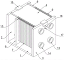
Fig. 1 is a schematic view of the overall structure of the present invention;
FIG. 2 is a partial schematic view of the present invention;
fig. 3 is a bottom view of the condensation plate of the present invention;
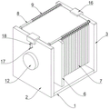
FIG. 4 is a rear view of the overall structure of the present invention;
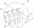
fig. 5 is an enlarged view of a portion a of fig. 3 according to the present invention.
The reference signs are: 1. a base; 2. a first support plate; 3. a second support plate; 4. an upper guide rail; 5. a lower guide rail; 6. a compression plate; 7. a condensing plate; 8. a round bar; 9. a collar; 10. a limiting rod; 11. a bolt; 12. a screw; 13. a chute; 14. a hot water pipe interface; 15. a cold water pipe interface; 16. mounting a plate; 17. a base plate; 18. an electric push rod.
Detailed Description
The technical solutions in the embodiments of the present invention will be described clearly and completely with reference to the drawings in the embodiments of the present invention, and it is obvious that the described embodiments are only some embodiments of the present invention, not all embodiments. Based on the embodiments in the present invention, all other embodiments obtained by a person skilled in the art without creative efforts all belong to the protection scope of the present invention.
Referring to the attached drawings of the specification, 1-5, the utility model provides a detachable plate condenser, including a base 1, the base 1 both ends are fixed respectively and are equipped with first backup pad 2 and second backup pad 3, be equipped with upper guide rail 4 and lower guide rail 5 between first backup pad 2 and the second backup pad 3, upper guide rail 4 sets up above lower guide rail 5, be equipped with pressure strip 6 between upper guide rail 4 and the lower guide rail 5, be equipped with a plurality of condenser plates 7 that distribute in proper order between pressure strip 6 and the second backup pad 3, fixed being equipped with two hot water pipe interfaces 14 that distribute from top to bottom and two cold water pipe interfaces 15 that distribute from top to bottom on the second backup pad 3, two cold water pipe interfaces 15 are established at hot water pipe interface 14 rear sides, are used for the condensation;
When the cold water pipe joint is used, a plurality of condensing plates 7 are firstly installed between the upper guide rail 4 and the lower guide rail 5 by an operator, then the pressing plate 6 is pushed to attach the condensing plates 7 together, then the two cold water pipe joints 15 and the two hot water pipe joints 14 are connected with an external pipeline to be used, when one condensing plate 7 goes wrong, the operator firstly uses the two electric push rods 18 to push the upper guide rail 4 to move upwards, so that the upper guide rail 4 is separated from the tops of the condensing plates 7, then the condensing plate 7 needing to be checked and replaced is found, the bolt 11 on the front side lantern ring 9 of the condensing plate 7 or the bolt 11 on the rear side lantern ring 9 is screwed, the condensing plate 7 can be detached from the lower guide rail 5, the rest condensing plates 7 are limited by the limiting rods 10 on the front side and the rear side, the rocking cannot occur, the structure is simple, and the disassembly is very convenient.
Referring to the specification figure 4, the utility model provides a detachable plate condenser, 2 one end threaded connection of first backup pad has screw 12, screw 12 one end is run through first backup pad 2 and is connected with 6 one end of pressure strip through the bearing, conveniently adjusts the position of pressure strip 6.
When the cooling device is installed, a worker rotates the limiting rod 10 onto the upper guide rail 4 by hand, then inserts the sliding groove 13 at the bottom end of the new condensation plate 7 onto the lower guide rail 5, finally uses the electric push rod 18 to drive the upper guide rail 4 to move downwards, and screws the bolt 11 on the lantern ring 9 again, and the position of the pressing plate 6 is adjusted by screwing the screw 12, so that the cooling device is simpler to use.
And finally: the above description is only for the preferred embodiment of the present invention and should not be taken as limiting the invention, and any modifications, equivalent replacements, improvements, etc. made within the spirit and principle of the present invention should be included in the protection scope of the present invention.
Claims (6)
1. A detachable plate condenser, includes base (1), its characterized in that: a first supporting plate (2) and a second supporting plate (3) are fixedly arranged at two ends of the base (1) respectively, an upper guide rail (4) and a lower guide rail (5) are arranged between the first supporting plate (2) and the second supporting plate (3), the upper guide rail (4) is arranged above the lower guide rail (5), a compression plate (6) is arranged between the upper guide rail (4) and the lower guide rail (5), and a plurality of condensation plates (7) which are distributed in sequence are arranged between the compression plate (6) and the second supporting plate (3);
go up guide rail (4) top front and back both sides and all be equipped with round bar (8), two round bar (8) outer walls all overlap and are equipped with a plurality of lantern rings (9), a plurality of lantern rings (9) and a plurality of condenser plate (7) one-to-one, and every lantern ring (9) bottom is all fixed and is equipped with gag lever post (10), gag lever post (10) contacts with condenser plate (7) outer wall, the inside equal threaded connection bolt (11) of every lantern ring (9), bolt (11) one end contacts with round bar (8) outer wall.
2. A removable plate condenser as claimed in claim 1, wherein: one end of the first supporting plate (2) is connected with a screw (12) in a threaded manner, and one end of the screw (12) penetrates through the first supporting plate (2) and is connected with one end of the pressing plate (6) through a bearing.
3. A removable plate condenser according to claim 1, wherein: the top ends and the bottom ends of the pressing plate (6) and the plurality of condensing plates (7) are respectively provided with a sliding groove (13), and the upper guide rail (4) and the lower guide rail (5) are respectively contacted with the plurality of sliding grooves (13).
4. A removable plate condenser as claimed in claim 1, wherein: two hot water pipe connectors (14) distributed up and down and two cold water pipe connectors (15) distributed up and down are fixedly arranged on the second supporting plate (3), and the two cold water pipe connectors (15) are arranged on the rear side of the hot water pipe connectors (14).
5. A removable plate condenser as claimed in claim 1, wherein: go up guide rail (4) both ends and all fixedly equipped with mounting panel (16), first backup pad (2) and second backup pad (3) keep away from one side outer wall each other and all fixedly equipped with backing plate (17), two backing plate (17) tops all fixedly are equipped with electric putter (18), two electric putter (18) tops respectively with two mounting panel (16) bottom fixed connection.
6. A removable plate condenser as claimed in claim 1, wherein: and the two ends of the round rod (8) are fixedly connected with the top end of the upper guide rail (4) through connecting plates.
Priority Applications (1)
| Application Number | Priority Date | Filing Date | Title |
|---|---|---|---|
| CN202222100461.9U CN218120265U (en) | 2022-08-10 | 2022-08-10 | Detachable plate-type condenser |
Applications Claiming Priority (1)
| Application Number | Priority Date | Filing Date | Title |
|---|---|---|---|
| CN202222100461.9U CN218120265U (en) | 2022-08-10 | 2022-08-10 | Detachable plate-type condenser |
Publications (1)
| Publication Number | Publication Date |
|---|---|
| CN218120265U true CN218120265U (en) | 2022-12-23 |
Family
ID=84521630
Family Applications (1)
| Application Number | Title | Priority Date | Filing Date |
|---|---|---|---|
| CN202222100461.9U Active CN218120265U (en) | 2022-08-10 | 2022-08-10 | Detachable plate-type condenser |
Country Status (1)
| Country | Link |
|---|---|
| CN (1) | CN218120265U (en) |
-
2022
- 2022-08-10 CN CN202222100461.9U patent/CN218120265U/en active Active
Similar Documents
| Publication | Publication Date | Title |
|---|---|---|
| CN210486614U (en) | Plate heat exchanger easy to replace and maintain | |
| CN208675565U (en) | A kind of boiler ceramic heating pipe | |
| CN223154064U (en) | Detachable plate heat exchanger with low flow resistance structure | |
| CN221630485U (en) | Efficient corrugated plate heat exchanger | |
| CN222445737U (en) | A quick-loading and unloading dust collector bag frame | |
| CN218998663U (en) | Heat pipe backboard air conditioner | |
| CN217584835U (en) | Air conditioner ventilation panel easy to disassemble | |
| CN213555403U (en) | Heating bed convenient to install and used for evaporator | |
| CN223807673U (en) | Heat exchanger applied to rotary dehumidifier | |
| CN217737975U (en) | Aluminum welded type segment radiator | |
| CN222849875U (en) | Fixing mechanism of heat exchange assembly | |
| CN221944956U (en) | Unsaturated polyester resin horizontal condenser | |
| CN218523982U (en) | Combined heat exchange equipment | |
| CN224215905U (en) | Plate heat exchanger convenient to dismouting | |
| CN213981685U (en) | Bearing pedestal with guide dismounting structure | |
| CN222317791U (en) | Detachable plate type heat exchanger | |
| CN223807390U (en) | A non-powered circulating phase change heat transfer split-type solar water heater | |
| CN221286932U (en) | Rectifying column condenser convenient to change | |
| CN222068950U (en) | A multifunctional condensing device | |
| CN221403617U (en) | Direct-current variable-frequency low-temperature circulating water chilling unit | |
| CN220981721U (en) | Light component tower bottom oil cooler | |
| CN222438588U (en) | Heat exchange coil structure convenient to disassemble and assemble | |
| CN222352955U (en) | A multi-stage series tube condenser | |
| CN222788463U (en) | Device for rectifying and recycling trioctyl trimellitate | |
| CN117212571B (en) | A bellows connection device that is easy to install and disassemble |
Legal Events
| Date | Code | Title | Description |
|---|---|---|---|
| GR01 | Patent grant | ||
| GR01 | Patent grant |