CN218111863U - High-efficient cutlery box forming die subassembly - Google Patents
High-efficient cutlery box forming die subassembly Download PDFInfo
- Publication number
- CN218111863U CN218111863U CN202222388458.1U CN202222388458U CN218111863U CN 218111863 U CN218111863 U CN 218111863U CN 202222388458 U CN202222388458 U CN 202222388458U CN 218111863 U CN218111863 U CN 218111863U
- Authority
- CN
- China
- Prior art keywords
- die
- forming
- molding
- assembly
- cylinder
- Prior art date
- Legal status (The legal status is an assumption and is not a legal conclusion. Google has not performed a legal analysis and makes no representation as to the accuracy of the status listed.)
- Active
Links
- 238000000465 moulding Methods 0.000 claims abstract description 73
- 230000007246 mechanism Effects 0.000 claims abstract description 65
- 238000000034 method Methods 0.000 claims abstract description 10
- 230000008569 process Effects 0.000 claims description 8
- 238000005485 electric heating Methods 0.000 claims description 7
- 238000003860 storage Methods 0.000 claims description 2
- 238000004519 manufacturing process Methods 0.000 abstract description 8
- 238000007493 shaping process Methods 0.000 abstract description 6
- 238000006073 displacement reaction Methods 0.000 abstract description 2
- 238000005516 engineering process Methods 0.000 abstract description 2
- 210000000078 claw Anatomy 0.000 description 13
- 239000000463 material Substances 0.000 description 10
- 235000012054 meals Nutrition 0.000 description 7
- 230000009471 action Effects 0.000 description 5
- 239000002131 composite material Substances 0.000 description 3
- 210000004400 mucous membrane Anatomy 0.000 description 3
- 239000004033 plastic Substances 0.000 description 3
- 239000000523 sample Substances 0.000 description 3
- XEEYBQQBJWHFJM-UHFFFAOYSA-N Iron Chemical compound [Fe] XEEYBQQBJWHFJM-UHFFFAOYSA-N 0.000 description 2
- 239000002313 adhesive film Substances 0.000 description 2
- 230000000694 effects Effects 0.000 description 2
- 235000013305 food Nutrition 0.000 description 2
- 238000010438 heat treatment Methods 0.000 description 2
- 210000004379 membrane Anatomy 0.000 description 2
- 239000012528 membrane Substances 0.000 description 2
- 238000004806 packaging method and process Methods 0.000 description 2
- 238000003856 thermoforming Methods 0.000 description 2
- FGRBYDKOBBBPOI-UHFFFAOYSA-N 10,10-dioxo-2-[4-(N-phenylanilino)phenyl]thioxanthen-9-one Chemical compound O=C1c2ccccc2S(=O)(=O)c2ccc(cc12)-c1ccc(cc1)N(c1ccccc1)c1ccccc1 FGRBYDKOBBBPOI-UHFFFAOYSA-N 0.000 description 1
- 240000009023 Myrrhis odorata Species 0.000 description 1
- 235000007265 Myrrhis odorata Nutrition 0.000 description 1
- 235000012550 Pimpinella anisum Nutrition 0.000 description 1
- 230000004075 alteration Effects 0.000 description 1
- 238000005266 casting Methods 0.000 description 1
- 230000000249 desinfective effect Effects 0.000 description 1
- 238000010586 diagram Methods 0.000 description 1
- 230000004927 fusion Effects 0.000 description 1
- 239000011521 glass Substances 0.000 description 1
- 239000003292 glue Substances 0.000 description 1
- 238000007373 indentation Methods 0.000 description 1
- 229910052742 iron Inorganic materials 0.000 description 1
- 238000010030 laminating Methods 0.000 description 1
- 238000012986 modification Methods 0.000 description 1
- 230000004048 modification Effects 0.000 description 1
- 239000003921 oil Substances 0.000 description 1
- 239000002245 particle Substances 0.000 description 1
- 229910052710 silicon Inorganic materials 0.000 description 1
- 239000010703 silicon Substances 0.000 description 1
- 238000006467 substitution reaction Methods 0.000 description 1
- XLYOFNOQVPJJNP-UHFFFAOYSA-N water Substances O XLYOFNOQVPJJNP-UHFFFAOYSA-N 0.000 description 1
Images




Landscapes
- Making Paper Articles (AREA)
Abstract
The utility model discloses a high-efficient cutlery box forming die subassembly belongs to cutlery box forming technology field, include: the device comprises a machine table, an upper rack, a die feeding mechanism and a forming mechanism; the upper rack is arranged on the machine table, and the die feeding mechanism is arranged on the upper rack; the molding mechanism comprises a first molding assembly and a second molding assembly which are used for finishing different molding procedures, and the first molding assembly and the second molding assembly are arranged in parallel; the first molding assembly comprises a first molding die and a first supercharging cylinder. The utility model discloses a mould mechanism, forming mechanism send that sets up can be through two sets of mould accurate displacements of servo motor control, and then utilize two sets of moulds to accomplish two different shaping processes simultaneously, have improved production efficiency and product quality widely, make manufacturing cost obtain effective control.
Description
Technical Field
The utility model relates to a cutlery box shaping technical field, concretely relates to high-efficient cutlery box forming die subassembly.
Background
The kind of cutlery box has a wide variety, and common cutlery box has generally: glass silicon, plastic and iron, wherein the plastic is divided into PC material and PP material. With the rapid development of composite material technology, the coated paper lunch box comes from time to time, and the coated paper is a composite material in which plastic particles are coated on the surface of paper through a casting machine, and is mainly characterized in that the composite material can resist oil and water and can be thermally sealed.
The existing octagonal laminated paper lunch box is made by single-mold thermoforming, is low in speed and efficiency, and improves the production cost to a certain extent. Therefore, an octagonal laminated paper lunch box forming device is provided. Therefore, the high-efficiency lunch box forming die assembly is provided.
SUMMERY OF THE UTILITY MODEL
The utility model discloses the technical problem that will solve lies in: how to solve current eight anise drenches that membrane paper cutlery box cornerite single mode thermoforming makes, speed is slow, inefficiency scheduling problem, provides a high-efficient cutlery box forming die subassembly.
The utility model solves the technical problems through the following technical proposal, and comprises a machine table, an upper rack, a mold feeding mechanism and a forming mechanism; the upper rack is erected on the machine table, and the die feeding mechanism is arranged on the upper rack; the molding mechanism comprises a first molding assembly and a second molding assembly which are used for finishing different molding procedures, and the first molding assembly and the second molding assembly are arranged in parallel;
the first forming assembly comprises a first forming die and a first booster cylinder, the first forming die comprises a first forming upper die and a first forming lower die, the first forming upper die is connected with a cylinder column of the first booster cylinder, the first forming lower die is arranged on the machine table, and a cylinder body of the first booster cylinder is connected with the die feeding mechanism;
the second forming assembly comprises a second pressure cylinder and a second forming die, the second forming die comprises a second forming upper die and a second forming lower die, the second forming upper die is connected with a cylinder column of the second pressure cylinder, the second forming lower die is arranged on the machine table, and a cylinder body of the second pressure cylinder is connected with the die feeding mechanism.
Furthermore, the upper rack comprises support columns and an upper bedplate, and the upper bedplate is connected with the machine table through a plurality of support columns.
Furthermore, the die feeding mechanism comprises a servo motor, a lead screw, two nut seats and two upper bridge plates which are arranged in parallel, wherein the servo motor is arranged on the upper platen, the lead screw is connected with the servo motor, the first pressurizing cylinder and the second pressurizing cylinder are respectively arranged on the two upper bridge plates, the upper bridge plates are connected with the nut seats, the nut seats are in threaded connection with the lead screw, and the upper bridge plates are in sliding connection with the upper platen.
Furthermore, the die feeding mechanism further comprises a sliding connection structure, the sliding connection structure comprises at least one sliding rail and at least one sliding block, the sliding rail is arranged on the upper bedplate, the sliding block is arranged on the upper bridge plate, and the sliding block is connected with the sliding rail in a sliding manner.
Furthermore, the first upper molding die and the second upper molding die are respectively provided with an air suction pipe, one end of each air suction pipe is communicated with an air suction hole formed in the first upper molding die/the second upper molding die, and the other end of each air suction pipe is connected with an external air storage tank through a control valve.
Furthermore, electric heating pipes are arranged inside the first lower forming die and the second lower forming die.
Compared with the prior art, the utility model has the following advantages: according to the high-efficiency lunch box forming die assembly, through the die conveying mechanism and the forming mechanism, the two sets of dies can be controlled to accurately displace through the servo motor, and then two different forming processes can be simultaneously completed by utilizing the two sets of dies, so that the production efficiency and the product quality are greatly improved, the production cost is effectively controlled, and the high-efficiency lunch box forming die assembly is worthy of being popularized and used.
Drawings
FIG. 1 is a schematic view of the overall structure of an octagonal laminated paper lunch box forming device in the embodiment of the present invention;
FIG. 2 is a schematic view of a partial structure of the paper stacking mechanism and the paper feeding mechanism according to the embodiment of the present invention;
FIG. 3 is a schematic view of a partial structure of an octagonal laminated paper lunch box forming device in an embodiment of the present invention;
fig. 4 is a schematic view of a partial structure of a forming mechanism in an embodiment of the present invention;
FIG. 5 is a schematic view of a partial structure of a stacking box collecting mechanism according to an embodiment of the present invention;
fig. 6 is a schematic structural diagram of a paper sheet for processing an octagonal paper lunch box according to an embodiment of the present invention.
Fig. 7 is an overall schematic view of the octagonal paper lunch box in the embodiment of the invention;
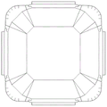
fig. 8 is a schematic top view of the octagonal paper lunch box in the embodiment of the present invention;
fig. 9 is a schematic view of the entire structure of the corner wrapping assembly according to the embodiment of the present invention;
fig. 10 is a schematic view of a partial structure of a corner-wrapping component according to an embodiment of the present invention.
Detailed Description
As shown in fig. 1 to 10, the following embodiments of the present invention are described in detail, and the present embodiment is implemented on the premise of the technical solution of the present invention, and a detailed implementation manner and a specific operation process are given, but the scope of the present invention is not limited to the following embodiments.
The embodiment provides a technical scheme: an octagonal laminated paper meal box forming device comprises a machine table 1, an upper rack, a paper stacking mechanism 3, a paper feeding mechanism 4, a mould feeding mechanism, a forming mechanism, a box stacking and collecting mechanism 8 and a conveying belt 9; the paper stacking mechanism 3, the paper feeding mechanism 4, the upper rack and the box stacking and collecting mechanism 8 are all arranged on the machine table 1 and used for stacking and collecting finished octagonal paper lunch boxes (octagonal laminated paper lunch boxes), the die feeding mechanism is arranged on the upper rack and used for moving the position of the forming mechanism, and the conveying belt 9 is arranged on one side of the box stacking and collecting mechanism 8 and used for conveying the octagonal paper lunch boxes to an automatic packaging machine;
forming mechanism includes first forming component, second forming component, first forming component with second forming component parallel arrangement, through first forming component carries out the cornerite (cornerite is handled promptly) when going on the shaping of pushing down to the scraps of paper, and hot briquetting becomes eight angle paper cutlery box rudiment, through second forming component carries out hot briquetting to the last oral margin part (U type groove) of eight angle paper cutlery box rudiment, accomplishes the shaping of whole eight angle paper cutlery box, and eight angle paper cutlery box just become the finished product after the bonding.
In this embodiment, the upper rack includes support pillars 22 and an upper platen 21, and the upper platen 21 is fixedly connected to the upper surface of the machine platform 1 through a plurality of support pillars 22.
In the present embodiment, the paper sheet stacking mechanism 3 includes a material seat plate 31, a first shutter 32, a second shutter 33; the material bedplate 31 through the connecting rod with the last fixed surface of board 1 is connected, the quantity of first baffle 32 is three, sets up respectively the both sides and the rear portion of material bedplate 31 top, the quantity of second baffle 33 is one, sets up the front portion of material bedplate 31 upper end, first baffle 32, the cooperation of second baffle 33 are used for spacing the scraps of paper that are used for processing eight-angle paper cutlery box to the length of second baffle 33 is less than the length of first baffle 32, is convenient for place the scraps of paper.
In this embodiment, the paper stacking mechanism 3 further includes a first lifting cylinder 35, a lower suction nozzle fixing plate 351, and a lower suction nozzle 352, wherein a cylinder post of the first lifting cylinder 35 is connected to the lower suction nozzle fixing plate 351, a cylinder body is fixedly connected to a lower portion of the machine platform 1, and the lower suction nozzle 352 is disposed on the lower suction nozzle fixing plate 351, and when necessary, the paper stacking mechanism is capable of facilitating suction by the paper feeding mechanism 4 by sucking a lowermost paper sheet of stacked paper sheets and adjusting a position of an uppermost paper sheet by the first lifting cylinder 35.
In this embodiment, the material seat plate 31 is provided with a reserved long hole for the lower nozzle fixing plate 351 to pass through.
In this embodiment, the first baffle 32 is fixedly connected to the upper platen 21 through a connecting frame 34.
In this embodiment, the second baffle 33 is fixedly connected to the upper end of the material seat plate 31.
In the present embodiment, the paper feeding mechanism 4 includes a shaftless cylinder 41, a connecting block 52, a second lifting cylinder 43; the shaftless cylinder 41 is installed on the upper surface of the machine table 1 through a portal frame, the cylinder body of the second lifting cylinder 43 is connected with the piston of the shaftless cylinder 41 through a connecting block 52, and a sliding rail and sliding block structure is arranged between the connecting block 52 and the portal frame and used for achieving a sliding guide effect.
In this embodiment, the paper feeding mechanism 4 further includes a paper sheet sucking structure, the paper sheet sucking structure includes an upper suction nozzle fixing plate 44 and an upper suction nozzle 441, the upper suction nozzle fixing plate 44 is connected to the cylinder post of the second lifting cylinder 43, the upper suction nozzle 441 is fixedly mounted on the upper suction nozzle fixing plate 44, and the height of the upper suction nozzle 441 can be adjusted by the second lifting cylinder 43, so as to facilitate sucking of paper sheets.
In this embodiment, the first molding assembly includes a first molding die and a first pressure cylinder 611, the first molding die is connected to a cylinder column of the first pressure cylinder 611, and a cylinder body of the first pressure cylinder 611 is connected to the mold feeding mechanism.
In this embodiment, the first molding die includes a first upper molding die 612 and a first lower molding die 613, the first upper molding die 612 is connected to a cylinder column of the first boost cylinder 611, and the first lower molding die 613 is disposed at an upper portion of the machine table 1.
In this embodiment, the first lower forming die 613 is provided with a corner wrapping assembly, by which the paper sheet can be pressed and formed while being subjected to corner wrapping.
In this embodiment, electric heating tubes are installed at two sides of the first lower molding die 613 for heating and fusing the mucous membrane at the corner wrap through high temperature. The electric heating tube is controlled by a constant temperature control circuit, temperature parameters are set, and the first molding lower die 613 is constant in temperature.
It should be noted that the contact surface of the semi-finished paper sheet with indentations in fig. 6 of the present invention with food is coated with a food-grade PE film, i.e. the above-mentioned mucous membrane. The laminating film has two functions, namely, the contact between food and paper is prevented, and the heat bonding is realized, so that glue is not used when the lunch box is formed, and the lunch box is safe and environment-friendly. When the lunch box is formed, the side with the adhesive film faces upwards.
In this embodiment, a lower mold positioning plate 6131 is disposed at a lower end of the first lower molding die 613, and the first lower molding die 613 is fixedly mounted on the upper end surface of the machine platform 1 through the lower mold positioning plate.
In this embodiment, an intermediate connecting plate 6132 is disposed between the lower positioning plate 6131 and the first lower molding die 613, and the first lower molding die 613 is connected to the lower positioning plate 6131 through the intermediate connecting plate 6132.
In this embodiment, the corner wrapping assembly includes a lower mold guiding claw 614, a lower mold stripper plate 615, a guiding claw guiding pillar 616, a stripper plate guiding pillar 617, and a supporting positioning plate 620, where the supporting positioning plate 620 is fixedly connected to the lower end of the machine platform 1, the guiding claw guiding pillar 616 and the stripper plate guiding pillar 617 sequentially penetrate through the intermediate connecting plate 6132, the lower mold positioning plate 6131, the supporting positioning plate 620, and the machine platform 1 and are slidably connected to the supporting positioning plate 620, the lower mold guiding claw 614 is fixedly connected to the upper end of the guiding claw guiding pillar 616, the lower mold stripper plate 615 is fixedly connected to the upper end of the stripper plate guiding pillar 617, and the lower mold stripper plate 615 is located inside the lower mold guiding claw 614.
In this embodiment, a guide pawl guide pillar spring 619 and a stripper plate guide pillar spring 618 are respectively sleeved outside the guide pawl guide pillar 616 and the stripper plate guide pillar 617, and the guide pawl guide pillar spring 619 and the stripper plate guide pillar spring 618 are both located between the intermediate connecting plate 6132 and the supporting and positioning plate 620, so as to perform the functions of resetting and jacking.
In this embodiment, linear bearings 621 are disposed between the guiding claw guiding post 616 and the stripper plate guiding post 617 and the supporting and positioning plate 620, and the guiding claw guiding post 616 and the stripper plate guiding post 617 are slidably connected to the supporting and positioning plate 620 through the linear bearings 621.
In this embodiment, a connection column 622 is disposed between the supporting and positioning plate 620 and the machine platform 1, and the supporting and positioning plate 620 is fixedly connected to the machine platform 1 through the connection column 622.
In this embodiment, the lower mold guiding claw 614 includes a square frame 6141 and four claw portions 6142, the four claw portions 6142 are respectively disposed at four corners of the square frame 6141 and are integrated with the square frame 6141, and the four claw portions 6142 correspond to the octagonal positions to be formed of the semi-finished paper pieces.
In this embodiment, the lower end surface of the lower mold stripper plate 615 is higher than the upper end surface of the square frame 6141.
In this embodiment, an (upward) octagonal bevel is formed in the middle position inside the first lower molding die 613, and the lower die guide claw 614 and the lower die stripper plate 615 are located in the octagonal bevel after descending to the maximum stroke.
It should be noted that, during the forming process, the semi-finished paper sheet with an impression in fig. 6 is accurately placed on the upper end surface of the stripper plate 615 through the first forming upper die 612, when the first forming upper die 612 is pressed down, the first forming upper die 612 presses the semi-finished paper sheet with an impression on the upper end surface of the lower die stripper plate 615, the lower die stripper plate 615 compresses the stripper plate guide post spring 618, after the stripper plate guide post 617 sinks for a distance, the to-be-formed octagon of the semi-finished paper sheet with an impression in fig. 6 contacts the lower die guide pawl 614, the to-be-formed octagon of the paper sheet is guided to be fitted to the angle of the first forming upper die 612 and collected, the lower die guide pawl 614 also compresses the guide pawl guide post spring 619, the guide jaw guide post 616 sinks, at this time, the lower die stripper plate 615 and the paper sheet sink into the first lower molding die 613 along with the first upper molding die 612, during which the to-be-molded octagonal of the paper sheet contacts the octagonal bevel of the first lower molding die 613, the to-be-molded octagonal is guided in along the octagonal bevel of the first lower molding die 613 under the cooperation of the lower die guide jaw 614, the wrap angle is naturally molded, then the electric heating plate of the first lower molding die 613 performs high-temperature fusion on the adhesive film at the wrap angle, and when the molding of the octagonal wrap angle of the product is completed, the first upper molding die 612 vacuum-adsorbs the octagonal paper box blank, takes out of the first lower molding die 613, and sends the box blank to the second molding die for further processing.
In this embodiment, the first upper molding die 612 is provided with a first air suction pipe 6121, the first air suction pipe 6121 is communicated with an air suction hole formed in the first upper molding die 612, and is used for sucking the octagonal paper lunch box blank, and the octagonal paper lunch box blank is moved to the second molding assembly under the driving of the die conveying mechanism and is used for performing hot press molding on the upper opening edge part of the octagonal paper lunch box blank.
In this embodiment, the second molding assembly includes a second supercharge cylinder 621 and a second molding mold, the second molding mold is connected to the cylinder post of the second supercharge cylinder 621, and the cylinder body of the second supercharge cylinder 621 is connected to the mold feeding mechanism.
In this embodiment, the second molding die includes a second upper molding die 622 and a second lower molding die 623, the second upper molding die 622 is connected to the cylinder post of the second boost cylinder 621, and the second lower molding die 623 is disposed on the upper portion of the machine table 1.
In this embodiment, be provided with second aspiration channel 6221 on the mould 622 in the second shaping, second aspiration channel 6221 with the hole intercommunication that induced drafts that mould 622 was seted up in the second shaping for absorb eight angle paper cutlery box finished products, under the drive of die feeding mechanism, remove eight angle paper cutlery box finished products to folding box collection mechanism 8 in and collect.
In this embodiment, electric heating tubes are installed at two sides of the interior of the second lower molding die 623, and are used for fusing the mucous membrane at the wrap angle through high temperature after heating. The electric heating tube is controlled by a constant temperature control circuit, temperature parameters are set, and the second molding lower die 623 is constant in temperature.
In this embodiment, the die feeding mechanism includes a first servo motor 51, a first lead screw 52 (horizontally disposed), two first nut seats 53, and two upper bridge plates 54, the first servo motor 51 is mounted on the upper platen 21, the first lead screw 52 is connected to the first servo motor 51, the first boost cylinder 611 and the second boost cylinder 621 are respectively disposed on the two upper bridge plates 54, the upper bridge plate 54 is connected to the first nut seat 53, and the first nut seat 53 is screwed to the first lead screw 52. The first screw 52 is driven to rotate by the first servo motor 51, so as to drive the two upper bridge plates 54 to move synchronously, and thus two different hot press forming processes and finished product collecting actions are completed simultaneously.
In this embodiment, a slide rail and slider structure is disposed between the upper bridge plate 54 and the upper bedplate 21, the upper bridge plate 54 and the upper bedplate 21 are slidably connected through the slide rail and slider structure, and the slide rail and slider structure plays a role in movement guiding and limiting.
In this embodiment, the stacked box collecting mechanism 8 includes a second servo motor 81, a second lead screw 82 (vertically disposed), a second nut seat 83, and a double L-shaped bracket 84, where the second servo motor 81 is disposed at the bottom of the machine table 1, the second lead screw 82 is connected to the second servo motor 81, and one end of the double L-shaped bracket 84 is connected to the second nut seat 83.
In this embodiment, two L shape supports 84 include two parallel arrangement's L shape branch, and the gap between two L shape branches is used for accepting the off-the-shelf bottom of eight angle paper cutlery box, and two L shape branches are used for supporting two off-the-shelf upper shed border portions of eight angle paper cutlery box, play to off-the-shelf support of eight angle paper cutlery box, limiting displacement.
In this embodiment, it still includes receipts material count probe and sterilamp to fold box collection mechanism 8, the sterilamp is installed board 1 is last, is located eight angle paper cutlery box finished product one side for play the effect of disinfecting eight angle paper cutlery box finished product, receive the material count probe setting on the support post 22 that is close to conveyer belt 9 one side, be used for counting eight angle paper cutlery box finished products through photoelectric counting.
In this embodiment, eight angles drench membrane paper cutlery box former still includes two at least gas holders 7, gas holder 7 is connected with each aspiration channel through each suction nozzle that control valve and the aforesaid corresponds, accomplishes the negative pressure and absorbs and release work.
The working principle is as follows: placing a paper sheet into the paper sheet stacking mechanism 3, sucking a next paper sheet from the paper sheet stacking mechanism 3 through the upper suction nozzle 441, sucking the paper sheet by the upper suction nozzle 441 on the paper feed mechanism 4, sending the paper sheet to the upper side of the first forming lower die 613 when the first forming upper die 612 moves forward, and then returning to the paper sheet stacking mechanism 3 to suck and send a next paper sheet; in a cycle, the process from the paper stacking mechanism 3 to the inside of the first forming lower die 613 is completed;
after the paper sheet reaches the first lower molding die 613, the die-feeding mechanism moves the first upper molding die 612 and the second upper molding die 622 to positions right above the corresponding first lower molding die 613 and second lower molding die 623;
the first upper molding die 612 drives the paper sheet downward to enter the first lower molding die 613 under the action of the pushing force of the first pressurizing cylinder 611, the paper sheet is wrapped at an angle by the paper sheet under the action of the corner wrapping assembly while the first upper molding die 612 is pressed downward, and the first upper molding die 612 presses the paper sheet downward in the first lower molding die 613 to form an octagonal paper lunch box embryonic form through hot press molding;
the second forming upper die 622 extrudes the octagonal paper lunch box rudiment downwards under the action of the driving force of the second booster cylinder 621 to enter the second forming lower die 623, and the octagonal paper lunch box rudiment is hot-pressed to form the upper edge part (U-shaped groove) of the paper box to be bonded, so that the bonding forming of the whole octagonal paper lunch box is completed, and the bonded octagonal paper lunch box becomes a finished product.
The first forming upper die 612 and the second forming upper die 622 move upwards simultaneously, the two forming upper dies are provided with air suction pipes, under the action of negative pressure, the octagon paper meal box rudiment and the octagon paper meal box finished product are carried to move together, after the octagon paper meal box rudiment and the octagon paper meal box finished product move to the top end, the first forming upper die 612 and the second forming upper die 622 move together to the direction of the conveying belt 9, the second forming upper die 622 moves to the position above the stacking and collecting mechanism 8, meanwhile, the first forming upper die 612 reaches the position above the second forming lower die 623, air blows outwards from the air suction pipes of the first forming upper die 612 and the second forming upper die 622, the octagon paper meal box rudiment on the first forming upper die 612 falls into the second forming lower die 623, and the octagon paper meal box finished product carried by the second forming upper die 622 falls into the stacking and collecting mechanism 8; then, the first servo motor 51 drives the first upper forming die 612 and the second upper forming die 622 to move towards the paper sheet direction, and the first upper forming die and the second upper forming die are moved to positions right above the corresponding lower forming dies to stop moving, and then the next forming process is completed;
octagonal paper lunch box finished products fall into the box stacking and collecting mechanism 8 after being demoulded from the second forming upper die 622, the falling carton finished products are supported by the 2L-shaped supporting rods, the receiving counting probes count, the number reaches a preset number (for example, 25), the double L-shaped supports 84 descend, the descending cartons reach the conveying belt 9, and the cartons are conveyed to the automatic packaging machine through the conveying belt 9 to be packaged.
In summary, the octagonal laminated paper lunch box forming equipment in the embodiment can control the two sets of dies to accurately displace through the servo motor through the arranged die feeding mechanism and the forming mechanism, and then two different forming processes can be simultaneously completed by utilizing the two sets of dies, so that the production efficiency and the product quality are greatly improved, and the production cost is effectively controlled; meanwhile, the wrap angle assembly is arranged, so that wrap angle processing can be conveniently carried out when the paper box is formed, the production efficiency is further improved, and the paper box is worthy of being popularized and used.
Although embodiments of the present invention have been shown and described, it is understood that the above embodiments are exemplary and should not be construed as limiting the present invention, and that variations, modifications, substitutions and alterations can be made to the above embodiments by those of ordinary skill in the art without departing from the scope of the present invention.
Claims (6)
1. The utility model provides a high-efficient cutlery box forming die subassembly which characterized in that includes: the device comprises a machine table, an upper rack, a die feeding mechanism and a forming mechanism; the upper rack is erected on the machine table, and the die feeding mechanism is arranged on the upper rack; the molding mechanism comprises a first molding assembly and a second molding assembly which are used for completing different molding processes, and the first molding assembly and the second molding assembly are arranged in parallel;
the first forming assembly comprises a first forming die and a first pressurizing cylinder, the first forming die comprises a first forming upper die and a first forming lower die, the first forming upper die is connected with a cylinder column of the first pressurizing cylinder, the first forming lower die is arranged on the machine table, and a cylinder body of the first pressurizing cylinder is connected with the die feeding mechanism;
the second forming assembly comprises a second pressure cylinder and a second forming die, the second forming die comprises a second forming upper die and a second forming lower die, the second forming upper die is connected with a cylinder column of the second pressure cylinder, the second forming lower die is arranged on the machine table, and a cylinder body of the second pressure cylinder is connected with the die feeding mechanism.
2. A high efficiency cutlery box forming die assembly as claimed in claim 1, wherein: the upper rack comprises support columns and an upper bedplate, and the upper bedplate is connected with the machine table through a plurality of support columns.
3. A high efficiency cutlery box forming die assembly as claimed in claim 2, wherein: the die feeding mechanism comprises a servo motor, a lead screw, two nut seats and two upper bridge plates which are arranged in parallel, the servo motor is arranged on the upper platen, the lead screw is connected with the servo motor, a first pressurizing cylinder and a second pressurizing cylinder are respectively arranged on the two upper bridge plates, the upper bridge plates are connected with the nut seats, the nut seats are in threaded connection with the lead screw, and the upper bridge plates are in sliding connection with the upper platen.
4. A high efficiency cutlery box forming die assembly as claimed in claim 3, wherein: the die conveying mechanism further comprises a sliding connection structure, the sliding connection structure comprises at least one sliding rail and at least one sliding block, the sliding rail is arranged on the upper bedplate, the sliding block is arranged on the upper bridge plate, and the sliding block is connected with the sliding rail in a sliding mode.
5. A high efficiency cutlery box forming die assembly as claimed in claim 4, wherein: the first upper forming die and the second upper forming die are both provided with air suction pipes, one end of each air suction pipe is communicated with an air suction hole formed in the first upper forming die/the second upper forming die, and the other end of each air suction pipe is connected with an external air storage tank through a control valve.
6. A high efficiency cutlery box forming die assembly as claimed in claim 5, wherein: electric heating pipes are arranged in the first lower forming die and the second lower forming die.
Priority Applications (1)
| Application Number | Priority Date | Filing Date | Title |
|---|---|---|---|
| CN202222388458.1U CN218111863U (en) | 2022-09-08 | 2022-09-08 | High-efficient cutlery box forming die subassembly |
Applications Claiming Priority (1)
| Application Number | Priority Date | Filing Date | Title |
|---|---|---|---|
| CN202222388458.1U CN218111863U (en) | 2022-09-08 | 2022-09-08 | High-efficient cutlery box forming die subassembly |
Publications (1)
| Publication Number | Publication Date |
|---|---|
| CN218111863U true CN218111863U (en) | 2022-12-23 |
Family
ID=84528677
Family Applications (1)
| Application Number | Title | Priority Date | Filing Date |
|---|---|---|---|
| CN202222388458.1U Active CN218111863U (en) | 2022-09-08 | 2022-09-08 | High-efficient cutlery box forming die subassembly |
Country Status (1)
| Country | Link |
|---|---|
| CN (1) | CN218111863U (en) |
Cited By (2)
| Publication number | Priority date | Publication date | Assignee | Title |
|---|---|---|---|---|
| CN115648714A (en) * | 2022-09-08 | 2023-01-31 | 黄山洁惠环保科技有限公司 | Octagonal laminated paper lunch box forming equipment |
| CN117325494A (en) * | 2023-11-13 | 2024-01-02 | 玉环市光明眼镜制造股份有限公司 | Oil press for manufacturing glasses legs |
-
2022
- 2022-09-08 CN CN202222388458.1U patent/CN218111863U/en active Active
Cited By (2)
| Publication number | Priority date | Publication date | Assignee | Title |
|---|---|---|---|---|
| CN115648714A (en) * | 2022-09-08 | 2023-01-31 | 黄山洁惠环保科技有限公司 | Octagonal laminated paper lunch box forming equipment |
| CN117325494A (en) * | 2023-11-13 | 2024-01-02 | 玉环市光明眼镜制造股份有限公司 | Oil press for manufacturing glasses legs |
Similar Documents
| Publication | Publication Date | Title |
|---|---|---|
| CN111287022A (en) | A paper product processing production line with heating and trimming functions | |
| CN207678086U (en) | A kind of automatic shattering fitting rewinding all-in-one machine | |
| CN102514240B (en) | Fully-automatic paper plate or meal box forming machine | |
| CN210362430U (en) | Plastic uptake packing carton cutting device | |
| CN213618610U (en) | Full-automatic paper box folding machine | |
| CN205631526U (en) | Bonder is folded to carton | |
| CN111395051B (en) | Paper product container processing method | |
| CN111907044B (en) | Thermoforming machine and one-mold three-action in-mold labeling conveying and packing production line | |
| CN106049191B (en) | A kind of paper mould integration upset automatic machine | |
| CN115648714A (en) | Octagonal laminated paper lunch box forming equipment | |
| CN213320538U (en) | Aluminum foil composite transparent Mylar film-making device for electronic products | |
| CN202319066U (en) | Automatic forming machine for paper discs or food boxes | |
| CN107054768B (en) | Automatic packaging machine | |
| CN218111864U (en) | Mould for processing corner wrapping of lunch box | |
| CN213383186U (en) | Multi-grid paper box forming machine | |
| CN109968735B (en) | Enclose strip shaping edge-shoveling bubble all-in-one | |
| CN222948733U (en) | A batch hot pressing shaping machine for paper tray production | |
| CN221602966U (en) | Stamping production line for metal stamping container | |
| CN211508147U (en) | Soft connection product automatic shaping device | |
| CN216506952U (en) | Ultrasonic three-dimensional forming machine | |
| CN214777093U (en) | Production line for automatically arranging inner film bags of carton | |
| CN115446887A (en) | Automatic cutting system, cutting production line and cutting method for injection molding parts | |
| CN214111466U (en) | Equipment of heat exchange core | |
| CN205631349U (en) | Count of thermoforming machine piles up manipulator | |
| CN210651924U (en) | Two-way hollow plate edge sealing die and two-way edge sealing machine for hollow plates |
Legal Events
| Date | Code | Title | Description |
|---|---|---|---|
| GR01 | Patent grant | ||
| GR01 | Patent grant |