CN218111117U - Concrete Specimen Automatic Vibration System - Google Patents
Concrete Specimen Automatic Vibration System Download PDFInfo
- Publication number
- CN218111117U CN218111117U CN202222076142.9U CN202222076142U CN218111117U CN 218111117 U CN218111117 U CN 218111117U CN 202222076142 U CN202222076142 U CN 202222076142U CN 218111117 U CN218111117 U CN 218111117U
- Authority
- CN
- China
- Prior art keywords
- test piece
- piece box
- base
- fixedly connected
- mounting frame
- Prior art date
- Legal status (The legal status is an assumption and is not a legal conclusion. Google has not performed a legal analysis and makes no representation as to the accuracy of the status listed.)
- Expired - Fee Related
Links
Images


Landscapes
- Sampling And Sample Adjustment (AREA)
Abstract
本申请公开了混凝土试件自动化振实系统,属于混凝土振实技术领域,包括底座,所述底座上圆周等距设有多个沿径向设置的支撑杆,所述支撑杆与底座转动连接,多个所述支撑杆相靠近的一端设置有驱动块,所述驱动块与各个支撑杆转动连接,所述底座位于驱动块下方设有往复机构,所述支撑杆远离驱动块的一端转动连接有安装架,所述安装架下方固定连接有试件盒,所述试件盒与底座滑动连接,所述安装架位于试件盒上方设有压板。该混凝土试件自动化振实系统,通过设置同一个驱动杆连接有多个支撑杆,使得该振实系统能够同时对多个混凝土试件进行振实,相较于单个振实的装置效率更高,节省了工作人员需要对多个混凝土试件进行振实的时间。

The application discloses an automatic vibration system for concrete specimens, which belongs to the technical field of concrete vibration, and includes a base on which a plurality of radially arranged support rods are equidistantly arranged on the circumference of the base, and the support rods are rotatably connected to the base. One end of the plurality of support rods close to each other is provided with a drive block, and the drive block is rotatably connected to each support rod. The base is located below the drive block and is provided with a reciprocating mechanism. A mounting frame, a test piece box is fixedly connected to the bottom of the mounting frame, the test piece box is slidably connected to the base, and the mounting frame is provided with a pressure plate above the test piece box. The automatic vibrating system for concrete specimens, by setting the same driving rod to connect multiple support rods, enables the vibrating system to vibrate multiple concrete specimens at the same time, which is more efficient than a single vibrating device , saving the staff time to vibrate multiple concrete specimens.
Description
技术领域technical field
本申请涉及混凝土振实技术领域,尤其涉及混凝土试件自动化振实系统。The present application relates to the technical field of concrete vibration, in particular to an automatic vibration system for concrete specimens.
背景技术Background technique
混凝土作为广泛应用的建筑材料,其性能的高低严重影响建筑的安全性和使用寿命。因此,为了验证混凝土的性能,需对混凝土进行力学试验,以分析混凝土的力学性能。在对混凝土的性能进行测试之前,需制备混凝土试件,按照指定的配比将水泥、沙子和水混合形成浆状混凝土,并制得的浆状混凝土倒入模具内振实、然后放入养护箱进行养护,再将养护好的混凝土试件脱模以进行各种试验,从而验证混凝土的强度是否满足要求。Concrete is widely used as a building material, and its performance seriously affects the safety and service life of buildings. Therefore, in order to verify the performance of concrete, it is necessary to conduct mechanical tests on concrete to analyze the mechanical properties of concrete. Before testing the performance of concrete, it is necessary to prepare concrete specimens, mix cement, sand and water according to the specified ratio to form slurry concrete, and pour the prepared slurry concrete into the mold to vibrate, and then put it into curing Box for curing, and then demould the cured concrete specimens to conduct various tests, so as to verify whether the strength of the concrete meets the requirements.
中国公告号为CN214173923U的实用新型专利公开了一种混凝土试件自动化振实系统,其包括底座,底座的上表面固定连接有支撑柱和支撑架,支撑柱和支撑架之间架设有横杆,横杆的一端与支撑柱铰接,横杆的另一端搭接在支撑架上,支撑架上设置有间断撞击横杆的冲击装置;横杆远离支撑柱的一端固定连接有用于放置模具的振实平台,振实平台上设置有压板,模具夹持在压板与振实平台之间,压板与振实平台之间设置有弹性件。The utility model patent with the Chinese notification number CN214173923U discloses a concrete specimen automatic vibration system, which includes a base, the upper surface of the base is fixedly connected with a support column and a support frame, and a cross bar is erected between the support column and the support frame. One end of the crossbar is hinged to the support column, and the other end of the crossbar is lapped on the support frame, and the support frame is provided with an impact device that intermittently hits the crossbar; the end of the crossbar away from the support column is fixedly connected with a vibrator for placing the mold A platform, a pressing plate is arranged on the vibrating platform, the mold is clamped between the pressing plate and the vibrating platform, and an elastic member is arranged between the pressing plate and the vibrating platform.
该混凝土试件自动化振实系统使用时能够通过弹性件使得压板能够始终对模具内的混凝土试件提供压力,解决了振实过程中压板压紧效果下降的问题,但该混凝土试件自动化振实系统使用仅支持对单个模具内的混凝土试件进行振实,而制备混凝土试件往往需要同时制备多个进行备用以作参考,这就导致使用该振实系统进行振实时效率不够,增加工作人员制备试件的时间。When the concrete specimen automatic vibration system is used, the elastic parts can make the pressure plate always provide pressure to the concrete specimen in the mold, which solves the problem that the compression effect of the pressure plate decreases during the vibration process, but the automatic vibration of the concrete specimen The system only supports the vibration of concrete specimens in a single mold, and the preparation of concrete specimens often requires multiple preparations for reference at the same time. The time to prepare the specimen.
为此,我们提出来一种混凝土试件自动化振实系统解决上述问题。For this reason, we propose an automatic vibration system for concrete specimens to solve the above problems.
实用新型内容Utility model content
本申请的目的是为了解决现有技术中,不能同时对多个混凝土试件进行振实的问题,而提出的一种混凝土试件自动化振实系统。The purpose of this application is to solve the problem in the prior art that multiple concrete test pieces cannot be vibrated at the same time, and propose an automatic concrete test piece vibrating system.
为了实现上述目的,本申请采用了如下技术方案:In order to achieve the above object, the application adopts the following technical solutions:
混凝土试件自动化振实系统,包括底座,所述底座上圆周等距设有多个支撑杆,所述支撑杆的长度方向沿底座的径向设置,所述支撑杆与底座转动连接,多个所述支撑杆相靠近的一端设置有驱动块,所述驱动块与各个支撑杆转动连接,所述底座位于驱动块下方设有往复机构,所述支撑杆远离驱动块的一端转动连接有安装架,所述安装架下方固定连接有试件盒,所述试件盒沿竖直方向与底座滑动连接,所述安装架位于试件盒上方设有压板;The automatic vibration system for concrete specimens includes a base, on which a plurality of support rods are equidistantly arranged on the circumference, the length direction of the support rods is arranged along the radial direction of the base, and the support rods are rotatably connected to the base. One end of the support rods close to each other is provided with a drive block, the drive block is rotatably connected to each support rod, the base is located below the drive block and is provided with a reciprocating mechanism, and the end of the support rod away from the drive block is rotatably connected to a mounting bracket , the test piece box is fixedly connected to the bottom of the mounting frame, and the test piece box is slidably connected to the base along the vertical direction, and the mounting frame is provided with a pressure plate above the test piece box;
所述往复机构包括固定连接在驱动块下方的驱动环,所述底座位于驱动块一侧固定连接有驱动电机,所述驱动电机输出轴固定连接有凸轮,所述凸轮位于驱动环内与驱动环抵触。The reciprocating mechanism includes a drive ring fixedly connected under the drive block, the base is fixedly connected with a drive motor on one side of the drive block, and the output shaft of the drive motor is fixedly connected with a cam, and the cam is located in the drive ring and connected to the drive ring. conflict.
通过设置凸轮和驱动环抵触,实现了当驱动电机带动凸轮转动时能够使驱动环上下移动。通过设置往复机构带动驱动块上下往复,实现了当驱动块上下往复时能够带动多个支撑杆转动,从而使得支撑杆另一端的试件盒上下抖动,将试件盒内的混凝土试件振实。By arranging the cam to be in conflict with the drive ring, the drive ring can be moved up and down when the drive motor drives the cam to rotate. By setting the reciprocating mechanism to drive the drive block to reciprocate up and down, it is realized that when the drive block reciprocates up and down, it can drive multiple support rods to rotate, so that the test piece box at the other end of the support bar shakes up and down, and the concrete test piece in the test piece box is vibrated .
优选的,所述底座位于试件盒两侧固定连接有限位条,所述试件盒两侧开设有限位槽,所述限位条位于限位槽内与试件盒滑动连接。Preferably, the base is fixedly connected with limiting strips on both sides of the test piece box, and limiting grooves are opened on both sides of the test piece box, and the limiting strips are located in the limiting grooves and slidably connected with the test piece box.
通过设置限位槽和限位条,实现了对试件盒的限位。By setting the limit groove and the limit bar, the limit of the test piece box is realized.
优选的,所述压板上方转动连接有螺纹杆,所述螺纹杆穿过安装架并与安装架螺纹连接。Preferably, a threaded rod is rotatably connected above the pressing plate, and the threaded rod passes through the mounting frame and is threadedly connected with the mounting frame.
通过设置螺纹杆,实现了能够通过螺纹杆控制压板移动。By setting the threaded rod, the movement of the pressure plate can be controlled by the threaded rod.
优选的,所述压板下方设有活动板,所述活动板与压板之间设有复位弹簧,所述复位弹簧两端分别与活动板和压板固定连接。Preferably, a movable plate is provided under the pressing plate, a return spring is provided between the movable plate and the pressing plate, and both ends of the returning spring are fixedly connected to the movable plate and the pressing plate respectively.
通过设置复位弹簧和活动板,实现了活动板能够为混凝土试件提供压力。By setting the return spring and the movable plate, it is realized that the movable plate can provide pressure for the concrete specimen.
优选的,所述螺纹杆远离压板的一端固定连接有驱动把手。Preferably, the end of the threaded rod away from the pressing plate is fixedly connected with a driving handle.
通过设置驱动把手,实现了更方便转动螺纹杆。By setting the driving handle, it is more convenient to turn the threaded rod.
优选的,所述试件盒下方开设有脱模孔,所述试件盒位于脱模孔内滑动连接有脱模杆。Preferably, a demoulding hole is opened under the test piece box, and the test piece box is slidably connected with a demoulding rod in the demoulding hole.
通过设置脱模孔内的脱模杆,实现了能够通过脱模杆对试件进行脱模。By setting the demoulding rod in the demoulding hole, it is realized that the test piece can be demoulded through the demoulding rod.
优选的,所述脱模杆位于试件盒内的一端固定连接有脱模板,所述试件盒位于脱模板下方开设有容纳槽,所述容纳槽与脱模板相适配。Preferably, one end of the stripping rod located in the test piece box is fixedly connected with a stripping plate, and the test piece box is provided with a receiving groove under the stripping plate, and the holding groove is adapted to the stripping plate.
通过设置脱模杆上的脱模板,以防止脱模板向下掉落脱离试件盒。By setting the stripping plate on the stripping rod to prevent the stripping plate from falling down and leaving the test piece box.
综上所述,该混凝土试件自动化振实系统,通过设置由往复机构驱动上下往复的驱动块,使得驱动块能够带动多个支撑杆上下转动,进而使得支撑杆另一端固定连接在安装架上的试件盒上下移动,试件盒上下移动的同时能够使混凝土试件振实,同一个驱动杆连接有多个支撑杆,这就使得该振实系统能够同时对多个混凝土试件进行振实,相较于单个振实的装置效率更高,节省了工作人员需要对多个混凝土试件进行振实的时间。To sum up, the automatic vibration system for concrete specimens, by setting the drive block driven by the reciprocating mechanism to reciprocate up and down, enables the drive block to drive multiple support rods to rotate up and down, so that the other end of the support rod is fixedly connected to the mounting frame The test piece box moves up and down, and the concrete test piece can be vibrated while the test piece box moves up and down. The same driving rod is connected with multiple support rods, which makes the vibration system capable of vibrating multiple concrete test pieces at the same time. Compared with a single vibrating device, it is more efficient and saves the time for staff to vibrate multiple concrete specimens.
附图说明Description of drawings
图1是本申请结构示意图;Fig. 1 is the structural representation of the present application;
图2是本申请俯视结构示意图;Fig. 2 is a schematic diagram of the top view structure of the present application;
图3是本申请结构侧面剖视图;Fig. 3 is a side sectional view of the structure of the present application;
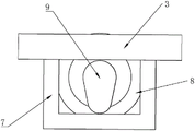
图4是本申请往复机构示意图。Fig. 4 is a schematic diagram of the reciprocating mechanism of the present application.
附图标记说明:Explanation of reference signs:
1、底座;2、支撑杆;3、驱动块;4、安装架;5、试件盒;6、压板;7、驱动环;8、驱动电机;9、凸轮;10、限位条;11、限位槽;12、螺纹杆;13、活动板;14、复位弹簧;15、驱动把手;16、脱模孔;17、脱模杆;18、脱模板;19、容纳槽。1. Base; 2. Support rod; 3. Drive block; 4. Mounting frame; 5. Test piece box; 6. Press plate; 7. Drive ring; 8. Drive motor; 9. Cam; 10. Limit bar; 11 12, threaded rod; 13, movable plate; 14, return spring; 15, driving handle; 16, demoulding hole; 17, demoulding rod; 18, stripping plate;
具体实施方式detailed description
下面将结合本申请实施例中的附图,对本申请实施例中的技术方案进行清楚、完整地描述,显然,所描述的实施例仅仅是本申请一部分实施例,而不是全部的实施例。The following will clearly and completely describe the technical solutions in the embodiments of the application with reference to the drawings in the embodiments of the application. Apparently, the described embodiments are only some of the embodiments of the application, not all of them.
参照图1、图2、图3,一种混凝土试件自动化振实系统,包括底座1,底座1上圆周等距设有多个支撑杆2,支撑杆2的长度方向沿底座1的径向设置,支撑杆2包括两端和杆部,支撑杆2的杆部与底座1转动连接,支撑杆2可以绕与底座1的连接点上下转动,多个支撑杆2相靠近的一端设置有驱动块3,驱动块3与各个支撑杆2转动连接,驱动块3上下移动时能够带动支撑杆2转动,底座1位于驱动块3下方设有往复机构,往复机构使得驱动块3上下往复运动,支撑杆2远离驱动块3的一端转动连接有安装架4,安装架4下方固定连接有试件盒5,试件盒5沿竖直方向与底座1滑动连接,当驱动块3带动支撑杆2一端上下移动时会位于另一端的试件盒5上下移动,从而使试件盒5内的混凝土振实。Referring to Fig. 1, Fig. 2 and Fig. 3, an automatic vibration system for concrete specimens includes a base 1, on which a plurality of
需要说明的是,支撑杆2两端均设置有条形槽,条形槽的条形长度方向沿支撑杆2的长度方向,支撑杆2两端通过条形槽分别与底座1、驱动块3的铰接轴建立转动连接。It should be noted that both ends of the
该混凝土试件自动化振实系统,使用时往复机构带动驱动块3上下移动,从而带动与驱动块3转动连接的多个支撑杆2上下摆动,进而使得支撑杆2另一端的试件盒5上下摆动,将多个混凝土试件进行振实。In the automatic vibration system for concrete specimens, the reciprocating mechanism drives the
参照图1、图3、图4,往复机构包括固定连接在驱动块3下方的驱动环7,驱动环7为方环状,底座1位于驱动块3一侧固定连接有驱动电机8,驱动电机8输出轴固定连接有凸轮9,凸轮9竖直设置,驱动电机8输出轴转动时带动凸轮9转动,凸轮9位于驱动环7内与驱动环7抵触,当凸轮9转动时能够带动驱动环7上下移动,从而带动驱动块3上下移动。With reference to Fig. 1, Fig. 3, Fig. 4, reciprocating mechanism comprises the
底座1位于试件盒5两侧固定连接有限位条10,限位条10竖直设置,试件盒5两侧开设有限位槽11,限位槽11与限位条10适配,限位条10位于限位槽11内与试件盒5滑动连接,通过限位条10对试件盒5进行限位,使得支撑杆2能够带动试件盒5上下移动。The base 1 is fixedly connected to the
参照图1、图3、图4,安装架4位于试件盒5上方设有压板6,压板6与试件盒5适配,压板6上方转动连接有螺纹杆12,螺纹杆12竖直设置在压板6上方,螺纹杆12上端穿过安装架4并与安装架4螺纹连接,当螺纹杆12转动时会驱动压板6上下移动,从而使得压板6能够将试件盒5内的混凝土进行压实。螺纹杆12远离压板6的一端固定连接有驱动把手15,驱动把手15位于压板6的上方,方便控制螺纹杆12转动。Referring to Fig. 1, Fig. 3 and Fig. 4, the mounting
压板6下方设有活动板13,活动板13平行于压板6,活动板13与压板6之间设有复位弹簧14,复位弹簧14两端分别与活动板13和压板6固定连接,复位弹簧14为活动板13提供弹力,当压板6下压时能够通过移动板对试件盒5内的混凝土试件进行挤压,并且复位弹簧14的存在能够使得混凝土试件表面下沉后,活动板13能够继续为混凝土提供压力。
参照图1、图3,试件盒5下方开设有脱模孔16,试件盒5位于脱模孔16内滑动连接有脱模杆17,脱模杆17可以在脱模孔16内上下滑动,从而将试件盒5内成型的混凝土试件顶出,方便混凝土试件的脱模。脱模杆17位于试件盒5内的一端固定连接有脱模板18,脱模板18与压板6平行,试件盒5位于脱模板18下方开设有容纳槽19,容纳槽19与脱模板18相适配,脱模板18能够被收纳到容纳槽19内,当需要脱模时,通过脱模杆17带动脱模板18将混凝土试件顶出,脱模板18与容纳槽19的配合用于防止脱模板18向下掉落脱离试件盒5。Referring to Fig. 1 and Fig. 3, a
工作原理:使用时,启动驱动电机8带动位于驱动块3下方的凸轮9转动,凸轮9通过与驱动环7抵触使得驱动环7上下移动,进而使得驱动环7带动驱动块3上下移动,驱动块3上下移动会通过支撑杆2带动支撑杆2另一端的试件盒5上下移动,从而使得试件盒5内的混凝土试件被振实;在混凝土试件被振实过程中,压板6上通过复位弹簧14连接的移动板会始终为混凝土试件提供压力,保证混凝土试件被压实;在振实完成后,可以通过脱模杆17和脱模板18将试件盒5内的混凝土试件顶出,方便脱模。Working principle: When in use, start the
以上所述,仅为本申请较佳的具体实施方式,但本申请的保护范围并不局限于此,任何熟悉本技术领域的技术人员在本申请揭露的技术范围内,根据本申请的技术方案及其申请构思加以等同替换或改变,都应涵盖在本申请的保护范围之内。The above is only a preferred embodiment of the present application, but the scope of protection of the present application is not limited thereto. Anyone familiar with the technical field within the technical scope disclosed in this application, according to the technical solutions of this application Any equivalent replacement or change of the concept of the application and its application shall be covered within the scope of protection of this application.
Claims (7)
Priority Applications (1)
| Application Number | Priority Date | Filing Date | Title |
|---|---|---|---|
| CN202222076142.9U CN218111117U (en) | 2022-08-06 | 2022-08-06 | Concrete Specimen Automatic Vibration System |
Applications Claiming Priority (1)
| Application Number | Priority Date | Filing Date | Title |
|---|---|---|---|
| CN202222076142.9U CN218111117U (en) | 2022-08-06 | 2022-08-06 | Concrete Specimen Automatic Vibration System |
Publications (1)
| Publication Number | Publication Date |
|---|---|
| CN218111117U true CN218111117U (en) | 2022-12-23 |
Family
ID=84521559
Family Applications (1)
| Application Number | Title | Priority Date | Filing Date |
|---|---|---|---|
| CN202222076142.9U Expired - Fee Related CN218111117U (en) | 2022-08-06 | 2022-08-06 | Concrete Specimen Automatic Vibration System |
Country Status (1)
| Country | Link |
|---|---|
| CN (1) | CN218111117U (en) |
-
2022
- 2022-08-06 CN CN202222076142.9U patent/CN218111117U/en not_active Expired - Fee Related
Similar Documents
| Publication | Publication Date | Title |
|---|---|---|
| CN108127098A (en) | A kind of well lid die casting | |
| CN112976295B (en) | Manufacturing method of high-strength prestressed concrete precast tubular pile | |
| CN115319909A (en) | Pre-tensioning method prestressed precast pile manufacturing equipment and method | |
| CN216442779U (en) | Forming die is used in wire pole production | |
| CN220049265U (en) | Dust collector is used in concrete production | |
| CN209050076U (en) | A kind of sand compaction device | |
| CN112248231A (en) | Concrete manufacturing equipment and using method thereof | |
| RU2607683C1 (en) | Plant forming blocks from wood concrete | |
| CN212445675U (en) | Light slat grouting and tamping mold device | |
| CN211818085U (en) | Concrete vibration equipment | |
| CN213288667U (en) | Auxiliary compaction device for forming of sliding gate | |
| CN116441494A (en) | Sand casting machine and sand casting demolding treatment method | |
| CN211030471U (en) | A cement test block forming device | |
| CN221087235U (en) | Mold stripping device for large-scale iron casting production | |
| CN220313650U (en) | Brick processing and forming die | |
| CN220699944U (en) | A kind of mortar material specimen forming device | |
| CN214173923U (en) | Automatic compaction system of concrete sample | |
| CN220945847U (en) | Manhole door pouring structure | |
| CN222318508U (en) | A concrete sampling device for building construction | |
| CN112247122A (en) | Post-processing system for manufacturing and processing engine cylinder block | |
| CN220348645U (en) | Building engineering concrete test block manufacturing equipment | |
| CN222819618U (en) | Extrusion molding die with die assembly guide structure | |
| CN207710994U (en) | A kind of asphalt mortar, bituminous mortar vibratory compaction molding device of automatic demoulding | |
| CN219855096U (en) | Concrete test block manufacturing device | |
| CN220207226U (en) | Cement mortar shaking table |
Legal Events
| Date | Code | Title | Description |
|---|---|---|---|
| GR01 | Patent grant | ||
| GR01 | Patent grant | ||
| CF01 | Termination of patent right due to non-payment of annual fee |
Granted publication date: 20221223 |