CN218082159U - An industrial vision automatic grinding and clamping mechanism - Google Patents
An industrial vision automatic grinding and clamping mechanism Download PDFInfo
- Publication number
- CN218082159U CN218082159U CN202221866562.0U CN202221866562U CN218082159U CN 218082159 U CN218082159 U CN 218082159U CN 202221866562 U CN202221866562 U CN 202221866562U CN 218082159 U CN218082159 U CN 218082159U
- Authority
- CN
- China
- Prior art keywords
- industrial vision
- grinding
- clamping mechanism
- bevel gear
- industrial
- Prior art date
- Legal status (The legal status is an assumption and is not a legal conclusion. Google has not performed a legal analysis and makes no representation as to the accuracy of the status listed.)
- Expired - Fee Related
Links
Images



Landscapes
- Constituent Portions Of Griding Lathes, Driving, Sensing And Control (AREA)
Abstract
本实用新型涉及工业视觉自动打磨技术领域,具体为一种工业视觉自动打磨夹持机构,包括工业视觉打磨机和伺服电机,所述工业视觉打磨机的底端固定安装有防滑底座,所述工业视觉打磨机的顶端装设有电机箱,所述电机箱的内部装设有伺服电机,所述伺服电机的输出轴固定安装有第一锥形齿轮,所述电机箱的内部装设有传动轴。本实用新型通过设置有伺服电机和放置板,将需要进行打磨的物品放置在放置板的顶端,将固定夹块抵触在被待打磨物品的表面,能够将待打磨物品进行夹持固定,通过伺服电机的转动能够使放置板进行水平移动,通过将放置板向右进行移动,通过打磨盘能够将放置板顶端固定的物品进行自动打磨。
The utility model relates to the technical field of industrial vision automatic grinding, specifically an industrial vision automatic grinding and clamping mechanism, which includes an industrial vision grinding machine and a servo motor. The bottom end of the industrial vision grinding machine is fixed with a non-slip base. The top of the visual grinding machine is equipped with a motor box, the interior of the motor box is equipped with a servo motor, the output shaft of the servo motor is fixedly installed with the first bevel gear, and the interior of the motor box is equipped with a transmission shaft . The utility model is provided with a servo motor and a placement plate, places the item to be polished on the top of the placement plate, and the fixed clamp block is in contact with the surface of the item to be polished, so that the item to be polished can be clamped and fixed. The rotation of the motor can make the placing plate move horizontally, and by moving the placing plate to the right, the fixed items on the top of the placing plate can be automatically polished by the grinding disc.
Description
技术领域technical field
本实用新型涉及工业视觉自动打磨技术领域,具体为一种工业视觉自动打磨夹持机构。The utility model relates to the technical field of automatic grinding of industrial vision, in particular to an automatic grinding and clamping mechanism of industrial vision.
背景技术Background technique
在工业视觉产品加工过程中,为了使得产品的表面能够更加光滑,需要将刚生产出的产品进行打磨加工,通常需要使用工业视觉自动打磨装置。In the process of industrial visual product processing, in order to make the surface of the product smoother, it is necessary to polish the newly produced product, usually using an industrial visual automatic grinding device.
现有的大多数自动打磨装置在将产品进行打磨时,需要通过手持的方式来将产品表面进行一点点的打磨,通过手持移动产品的方式进行打磨,产品打磨出来的精准度较差,而且手持产品进行打磨稳定性较差,因此亟需设计一种工业视觉自动打磨夹持机构。Most of the existing automatic grinding devices need to grind the surface of the product a little by hand when grinding the product, and the grinding is carried out by moving the product by hand. The accuracy of the product grinding is poor, and the hand-held The grinding stability of the product is poor, so it is urgent to design an industrial vision automatic grinding and clamping mechanism.
实用新型内容Utility model content
本实用新型的目的在于提供一种工业视觉自动打磨夹持机构,以解决上述背景技术中提出的通过手持产品的方式进行打磨,产品打磨出的精准度较差,而且手持产品进行打磨稳定性较差的问题。The purpose of this utility model is to provide an industrial visual automatic grinding and clamping mechanism to solve the problem of grinding by hand-held products in the above background technology, the accuracy of product grinding is poor, and the stability of grinding hand-held products bad question.
为实现上述目的,本实用新型提供如下技术方案:一种工业视觉自动打磨夹持机构,包括工业视觉打磨机和伺服电机,所述工业视觉打磨机的底端固定安装有防滑底座,所述工业视觉打磨机的顶端装设有电机箱,所述电机箱的内部装设有伺服电机,所述伺服电机的输出轴固定安装有第一锥形齿轮,所述电机箱的内部装设有传动轴,且传动轴的表面固定安装有第二锥形齿轮。In order to achieve the above purpose, the utility model provides the following technical solutions: an industrial vision automatic grinding and clamping mechanism, including an industrial vision grinding machine and a servo motor, the bottom of the industrial vision grinding machine is fixed with a non-slip base, the industrial vision The top of the visual grinding machine is equipped with a motor box, the interior of the motor box is equipped with a servo motor, the output shaft of the servo motor is fixedly installed with the first bevel gear, and the interior of the motor box is equipped with a transmission shaft , and a second bevel gear is fixedly installed on the surface of the transmission shaft.
优选的,所述工业视觉打磨机的顶端装设有限位框,所述限位框的顶端装设有放置板,所述工业视觉打磨机的顶端固定安装有打磨机箱。Preferably, a limit frame is installed on the top of the industrial vision grinder, a placement plate is installed on the top of the limit frame, and a grinding case is fixedly installed on the top of the industrial vision grinder.
优选的,所述第一锥形齿轮的侧面与第二锥形齿轮的底端相啮合,且第一锥形齿轮的侧面与第二锥形齿轮的底端组成转动式结构。Preferably, the side surface of the first bevel gear meshes with the bottom end of the second bevel gear, and the side surface of the first bevel gear and the bottom end of the second bevel gear form a rotating structure.
优选的,所述限位框的内部装设有内螺纹套筒,所述内螺纹套筒的内部插设有伸缩螺纹杆,所述伸缩螺纹杆的侧面装设有限位滑块,所述内螺纹套筒的侧面与传动轴的侧面固定相连,所述内螺纹套筒的内部开设有内螺纹,且内螺纹套筒的内部与伸缩螺纹杆的表面组成螺旋转动式结构,所述限位框的顶端开设有一组矩形孔槽,所述限位滑块的表面能够卡合在限位框顶端开设的矩形孔槽内,并且能够进行水平滑动。Preferably, an internally threaded sleeve is installed inside the limiting frame, a telescopic threaded rod is inserted inside the internally threaded sleeve, and a limit slider is installed on the side of the telescopically threaded rod. The side of the threaded sleeve is fixedly connected with the side of the transmission shaft. The interior of the internal thread sleeve is provided with internal threads, and the interior of the internal thread sleeve and the surface of the telescopic threaded rod form a spiral rotating structure. The limit frame There is a set of rectangular holes on the top of the frame, and the surface of the limit slider can be engaged in the rectangular holes on the top of the limit frame, and can slide horizontally.
优选的,所述放置板的顶端固定安装有限位块,所述限位块的表面固定安装有内螺纹固定块,所述内螺纹固定块的内部插设有螺栓,所述螺栓的一端装设有固定夹块,所述螺栓能够在限位块的内部进行伸缩滑动。Preferably, a limit block is fixedly installed on the top of the placing plate, and an internal thread fixing block is fixedly installed on the surface of the limit block, and a bolt is inserted inside the internal thread fixing block, and one end of the bolt is installed There is a fixed clamp block, and the bolt can telescopically slide inside the limit block.
优选的,所述打磨机箱的顶端装设有控制箱,所述打磨机箱的侧面装设有打磨盘。Preferably, a control box is installed on the top of the grinding machine box, and a grinding disc is installed on the side of the grinding machine box.
与现有技术相比,本实用新型的有益效果是:Compared with the prior art, the beneficial effects of the utility model are:
1、通过设置有伺服电机和放置板,将需要进行打磨的物品放置在放置板的顶端,将固定夹块抵触在被待打磨物品的表面,能够将待打磨物品进行夹持固定,通过伺服电机的转动能够使放置板进行水平移动,通过将放置板向右进行移动,通过打磨盘能够将放置板顶端固定的物品进行自动打磨。1. By setting the servo motor and the placement plate, the item to be polished is placed on the top of the placement plate, and the fixed clamp block is in contact with the surface of the item to be polished, so that the item to be polished can be clamped and fixed. Through the servo motor The rotation can make the placing plate move horizontally, and by moving the placing plate to the right, the fixed items on the top of the placing plate can be automatically polished by the grinding disc.
附图说明Description of drawings
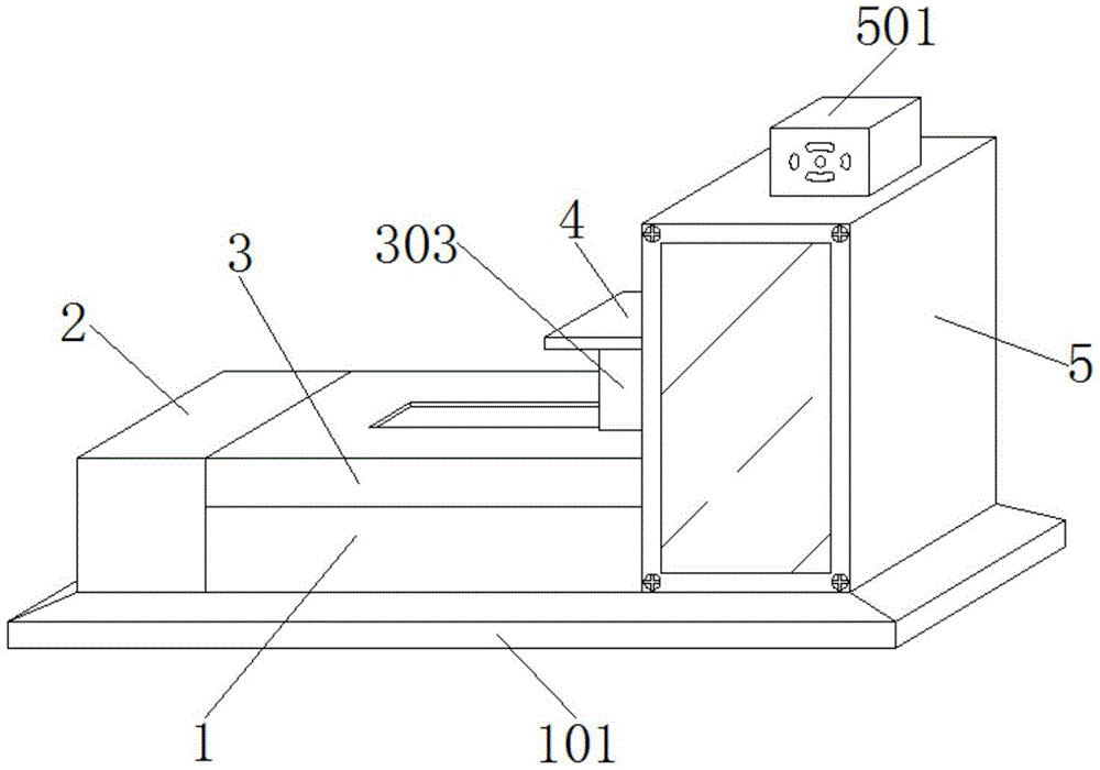
图1为本实用新型的结构三维示意图;Fig. 1 is the structural three-dimensional schematic diagram of the present utility model;
图2为本实用新型的结构正视剖面示意图;Fig. 2 is the schematic cross-sectional view of the structure of the utility model;
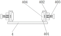
图3为本实用新型的放置板结构侧视示意图;Fig. 3 is a schematic side view of the placement plate structure of the present invention;
图4为本实用新型的限位滑块结构三维示意图。Fig. 4 is a three-dimensional schematic diagram of the structure of the limit slider of the present invention.
图中:1、工业视觉打磨机;101、防滑底座;2、电机箱;201、伺服电机;202、第一锥形齿轮;203、传动轴;204、第二锥形齿轮;3、限位框;301、内螺纹套筒;302、伸缩螺纹杆;303、限位滑块;4、放置板;401、限位块;402、内螺纹固定块;403、螺栓;404、固定夹块;5、打磨机箱;501、控制箱;502、打磨盘。In the figure: 1. Industrial visual grinding machine; 101. Anti-slip base; 2. Motor box; 201. Servo motor; 202. First bevel gear; 203. Transmission shaft; 204. Second bevel gear; 3. Limit Frame; 301, internal thread sleeve; 302, telescopic threaded rod; 303, limit slider; 4, place plate; 401, limit block; 402, internal thread fixed block; 403, bolt; 404, fixed clip block; 5. Grinding chassis; 501, control box; 502, grinding disc.
具体实施方式detailed description
下面将结合本实用新型实施例中的附图,对本实用新型实施例中的技术方案进行清楚、完整地描述,显然,所描述的实施例仅仅是本实用新型一部分实施例,而不是全部的实施例。基于本实用新型中的实施例,本领域普通技术人员在没有做出创造性劳动前提下所获得的所有其他实施例,都属于本实用新型保护的范围。The technical solutions in the embodiments of the present invention will be clearly and completely described below in conjunction with the accompanying drawings in the embodiments of the present invention. Obviously, the described embodiments are only part of the embodiments of the present invention, not all of them. example. Based on the embodiments of the present utility model, all other embodiments obtained by persons of ordinary skill in the art without making creative efforts belong to the scope of protection of the present utility model.
请参阅图1-4,本实用新型提供的一种实施例:Please refer to Fig. 1-4, a kind of embodiment provided by the utility model:
一种工业视觉自动打磨夹持机构,包括工业视觉打磨机1和伺服电机201,本申请中使用的伺服电机201为市场上可直接购买到的产品,其原理和连接方式均为本领域技术人员熟知的现有技术,故在此不再赘述,工业视觉打磨机1的底端固定安装有防滑底座101,工业视觉打磨机1的顶端装设有电机箱2,电机箱2的内部装设有伺服电机201,伺服电机201的输出轴固定安装有第一锥形齿轮202,电机箱2的内部装设有传动轴203,且传动轴203的表面固定安装有第二锥形齿轮204。An industrial vision automatic grinding and clamping mechanism, including an industrial
进一步的,工业视觉打磨机1的顶端装设有限位框3,限位框3的顶端装设有放置板4,工业视觉打磨机1的顶端固定安装有打磨机箱5。Further, a
进一步的,第一锥形齿轮202的侧面与第二锥形齿轮204的底端相啮合,且第一锥形齿轮202的侧面与第二锥形齿轮204的底端组成转动式结构。Further, the side surface of the
进一步的,限位框3的内部装设有内螺纹套筒301,内螺纹套筒301的内部插设有伸缩螺纹杆302,伸缩螺纹杆302的侧面装设有限位滑块303,内螺纹套筒301的侧面与传动轴203的侧面固定相连,内螺纹套筒301的内部开设有内螺纹,且内螺纹套筒301的内部与伸缩螺纹杆302的表面组成螺旋转动式结构,限位框3的顶端开设有一组矩形孔槽,限位滑块303的表面能够卡合在限位框3顶端开设的矩形孔槽内,并且能够进行水平滑动。Further, the inside of the limiting
进一步的,放置板4的顶端固定安装有限位块401,限位块401的表面固定安装有内螺纹固定块402,内螺纹固定块402的内部插设有螺栓403,螺栓403的一端装设有固定夹块404,螺栓403能够在限位块401的内部进行伸缩滑动。Further, the top of the
进一步的,打磨机箱5的顶端装设有控制箱501,打磨机箱5的侧面装设有打磨盘502。Further, a
工作原理:当需要将物品固定住进行自动打磨时,首先将本装置外接电源,从而为本装置提供电力支持,将需要进行打磨的物品放置在放置板4的顶端,通过转动螺栓403能够使螺栓403在内螺纹固定块402的内部进行伸缩,通过螺栓403的伸缩能够使固定夹块404进行移动,将固定夹块404抵触在被待打磨物品的表面,能够将待打磨物品进行夹持固定,通过伺服电机201的转动能够使传动轴203进行转动,通过传动轴203的转动能够使内螺纹套筒301进行转动,通过内螺纹套筒301的转动能够使伸缩螺纹杆302进行伸缩滑动,通过该方式能够使限位滑块303进行水平移动,从而能够使放置板4进行水平移动,通过将放置板4向右进行移动,通过打磨盘502能够将放置板4顶端固定的物品进行自动打磨。Working principle: When it is necessary to fix the item for automatic grinding, first connect the device to an external power supply to provide power support for the device, place the item to be polished on the top of the
对于本领域技术人员而言,显然本实用新型不限于上述示范性实施例的细节,而且在不背离本实用新型的精神或基本特征的情况下,能够以其他的具体形式实现本实用新型。因此,无论从哪一点来看,均应将实施例看作是示范性的,而且是非限制性的,本实用新型的范围由所附权利要求而不是上述说明限定,因此旨在将落在权利要求的等同要件的含义和范围内的所有变化囊括在本实用新型内。不应将权利要求中的任何附图标记视为限制所涉及的权利要求。It is obvious to those skilled in the art that the present invention is not limited to the details of the above exemplary embodiments, and that the present invention can be implemented in other specific forms without departing from the spirit or essential features of the present invention. Therefore, no matter from all points of view, the embodiments should be regarded as exemplary and non-restrictive, and the scope of the present invention is defined by the appended claims rather than the above description, so it is intended to fall within the scope of the claims All changes within the meaning and range of equivalents of the required elements are included in the present invention. Any reference sign in a claim should not be construed as limiting the claim concerned.
Claims (6)
Priority Applications (1)
| Application Number | Priority Date | Filing Date | Title |
|---|---|---|---|
| CN202221866562.0U CN218082159U (en) | 2022-07-20 | 2022-07-20 | An industrial vision automatic grinding and clamping mechanism |
Applications Claiming Priority (1)
| Application Number | Priority Date | Filing Date | Title |
|---|---|---|---|
| CN202221866562.0U CN218082159U (en) | 2022-07-20 | 2022-07-20 | An industrial vision automatic grinding and clamping mechanism |
Publications (1)
| Publication Number | Publication Date |
|---|---|
| CN218082159U true CN218082159U (en) | 2022-12-20 |
Family
ID=84483194
Family Applications (1)
| Application Number | Title | Priority Date | Filing Date |
|---|---|---|---|
| CN202221866562.0U Expired - Fee Related CN218082159U (en) | 2022-07-20 | 2022-07-20 | An industrial vision automatic grinding and clamping mechanism |
Country Status (1)
| Country | Link |
|---|---|
| CN (1) | CN218082159U (en) |
-
2022
- 2022-07-20 CN CN202221866562.0U patent/CN218082159U/en not_active Expired - Fee Related
Similar Documents
| Publication | Publication Date | Title |
|---|---|---|
| CN212399074U (en) | Inferior gram force board deburring grinding device | |
| CN210997864U (en) | Grinding machine for machining | |
| CN210938543U (en) | Arc-shaped grinding machine structure | |
| CN212240559U (en) | Frock clamp and system for inclined plane grinding and polishing | |
| CN214024835U (en) | Surface passivation device of transistor | |
| CN217167849U (en) | Edging device for metal part machining | |
| CN216504229U (en) | Polishing machine with workpiece rotation supporting mechanism | |
| CN216577182U (en) | High-precision linear guide rail grinding machine based on electric permanent magnetic chuck | |
| CN212601204U (en) | Electric lifting adjusting mechanism for tile-shaped magnet grinding machine | |
| CN213646887U (en) | Paper tube surface layer grinding machine | |
| CN213289809U (en) | Grinding machine that suitability is strong | |
| CN218801235U (en) | Automatic sample block grinding and polishing device for casting detection | |
| CN211305806U (en) | Polishing device for stainless steel box | |
| CN210476538U (en) | Burnishing device is used in steel production | |
| CN213828374U (en) | A grinding device for vehicle parts processing | |
| CN214292624U (en) | Optimized machining round grinding clamping device | |
| CN216098018U (en) | Polishing equipment | |
| CN215700571U (en) | Mechanical automation is with grinding device who is convenient for centre gripping work piece | |
| CN212886950U (en) | Outer polishing device for machining telescopic magnetic connecting rod | |
| CN222627297U (en) | A double-sided polishing device for light-guiding acrylic plate | |
| CN218518361U (en) | Polishing device for metal aluminum wheel machining | |
| CN221834025U (en) | Deckle edge grinding device is used in metalwork processing | |
| CN222920334U (en) | A support device for producing resin-coated abrasive tools | |
| CN210232528U (en) | Grinding device for computer main machine accessory | |
| CN215881027U (en) | Novel numerical control machining double-ended grinding machine |
Legal Events
| Date | Code | Title | Description |
|---|---|---|---|
| GR01 | Patent grant | ||
| GR01 | Patent grant | ||
| CF01 | Termination of patent right due to non-payment of annual fee |
Granted publication date: 20221220 |
|
| CF01 | Termination of patent right due to non-payment of annual fee |