CN218050028U - Vehicle frame plate stamping device - Google Patents
Vehicle frame plate stamping device Download PDFInfo
- Publication number
- CN218050028U CN218050028U CN202222729759.6U CN202222729759U CN218050028U CN 218050028 U CN218050028 U CN 218050028U CN 202222729759 U CN202222729759 U CN 202222729759U CN 218050028 U CN218050028 U CN 218050028U
- Authority
- CN
- China
- Prior art keywords
- plate
- metal plate
- roller
- processed metal
- baffles
- Prior art date
- Legal status (The legal status is an assumption and is not a legal conclusion. Google has not performed a legal analysis and makes no representation as to the accuracy of the status listed.)
- Expired - Fee Related
Links
Images


Landscapes
- Press Drives And Press Lines (AREA)
Abstract
本实用新型公开了一种车架板材冲压装置,涉及冲压装置技术领域,具有便于推动加工金属板移动,从而调整加工金属板冲压切割位置的优点,其技术方案要点是:包括工作台以及设置在工作台上的固定架,固定架上设有冲压机,工作台设有用于放置加工金属板的固定板,且固定板位于冲压机的下方,固定板设有用于推动加工金属板在固定板上进行移动的移动件,工作台上嵌设有下模具,冲压机上设有用于通过与下模具的配合对加工金属板进行冲压切割的上模具。
The utility model discloses a punching device for a frame plate, which relates to the technical field of punching devices, and has the advantages of being convenient to push and move a processed metal plate so as to adjust the stamping and cutting position of the processed metal plate. The fixed frame on the working table is equipped with a punching machine, the working table is provided with a fixed plate for placing the processed metal plate, and the fixed plate is located under the punching machine, and the fixed plate is provided for pushing the processed metal plate on the fixed plate As for the movable part, a lower mold is embedded on the workbench, and an upper mold for stamping and cutting the processed metal plate is provided on the punching machine by cooperating with the lower mold.
Description
技术领域technical field
本实用新型涉及冲压装置技术领域,具体为一种车架板材冲压装置。The utility model relates to the technical field of punching devices, in particular to a punching device for vehicle frame plates.
背景技术Background technique
电动车在生产加工过程中,多数车体由若干个板材焊接而成,而这些板材在加工过程中会通过冲压设备对其进行冲压工作。冲压机是通过电动机驱动飞轮,并通过离合器,传动齿轮带动曲柄连杆机构使滑块上下运动,带动模具对板材、带材、管材和型材等施加外力,使之产生塑性变形或分离,从而获得所需形状和尺寸的工件(冲压件)。During the production and processing of electric vehicles, most of the car bodies are welded by several plates, and these plates will be stamped by stamping equipment during the processing process. The stamping machine drives the flywheel through the motor, and through the clutch, the transmission gear drives the crank linkage mechanism to move the slider up and down, and drives the mold to exert external force on the plates, strips, pipes and profiles, so that they are plastically deformed or separated, so as to obtain Workpieces (stampings) of the desired shape and size.
目前,市场上的申请号为CN202020656316.7的中国专利公开了一种金属板材加工用冲压模具,包括底架,所述底架的顶端固定连接有工作台,所述工作台的顶端活动连接有加工金属板,所述加工金属板的顶端活动连接有压料板,所述压料板中部的两侧分别设有孔且通过孔分别活动连接有外环刀和内环刀,所述外环刀的底端固定连接有定位销,所述外环刀的顶端固定连接上模座,所述上模座的中部固定连接有冲压杆,所述工作台中部的两侧分别设有成品出料口和废料出料口,所述工作台底端的中间固定连接有传送带支架,所述传送带支架的顶端活动连接有销轴,所述传送带支架通过上侧销轴活动连接有废料传送带,且通过下侧销轴活动连接有成品传送带,所述底架正面的一侧固定安装有成品箱,所述底架正面的另一侧固定连接有废料箱。At present, the Chinese patent with the application number CN202020656316.7 on the market discloses a stamping die for sheet metal processing, including a chassis, the top of the chassis is fixedly connected to a workbench, and the top of the workbench is movably connected to a A metal plate is processed, the top of the processed metal plate is movably connected with a binder plate, holes are respectively provided on both sides of the middle part of the binder plate, and an outer ring knife and an inner ring knife are respectively movably connected through the holes, and the outer ring The bottom end of the knife is fixedly connected with a positioning pin, the top end of the outer ring knife is fixedly connected with the upper mold base, the middle part of the upper mold base is fixedly connected with a stamping rod, and the two sides of the middle part of the workbench are respectively equipped with finished product discharge The middle of the bottom end of the workbench is fixedly connected with a conveyor belt bracket, and the top of the conveyor belt bracket is movably connected with a pin shaft, and the conveyor belt bracket is movably connected with a waste conveyor belt through the upper side pin shaft, and through the lower The side pin shaft is movably connected with a finished product conveyor belt, one side of the front of the underframe is fixedly equipped with a finished product box, and the other side of the front of the underframe is fixedly connected with a waste box.
通过将加工金属板放置冲压机工作台上的下模座上,放下压料板,打开冲压机开关,在冲压杆的带动下上模座下落,内环刀冲压切割加工金属板,废料自废料出料口落下工作台,经废料传送带送至废料箱,推动加工金属板前进一定距离,冲压杆再次落下,外环刀与内环刀同时下落,定位销落至内环切口处,外环刀与内环刀同时切割加工金属板,成品自成品出料口落下被传送至成品箱,废料自废料出料口落下被传送至废料箱。By placing the processed metal plate on the lower die base on the workbench of the punching machine, lowering the pressing plate, turning on the switch of the punching machine, the upper die base falls under the drive of the punching rod, and the inner ring knife stamps and cuts the processed metal plate, and the waste is produced from the waste. The discharge port falls to the working table, and is sent to the waste bin through the waste conveyor belt, and the processed metal plate is pushed forward for a certain distance, the stamping rod falls again, the outer ring knife and the inner ring knife fall at the same time, the positioning pin falls to the incision of the inner ring, and the outer ring knife The metal plate is cut and processed at the same time as the inner ring knife. The finished product falls from the finished product outlet and is conveyed to the finished product box, and the waste material falls from the waste material outlet and is conveyed to the waste box.
上述申请没有具体公开推动加工金属板移动的结构,需要人工推动加工金属板前进调整加工金属板的冲压切割位置,使用不便,因此本申请提供一种推动加工金属板移动的结构。以解决需要人工推动加工金属板移动,从而调整加工金属板冲压切割位置的技术问题。The above application does not specifically disclose the structure for pushing the processed metal plate to move. It is inconvenient to use to manually push the processed metal plate forward to adjust the punching and cutting position of the processed metal plate. Therefore, the present application provides a structure for pushing the processed metal plate to move. In order to solve the technical problem that it is necessary to manually push the processed metal plate to move, thereby adjusting the stamping and cutting position of the processed metal plate.
实用新型内容Utility model content
针对上述存在的技术不足,本实用新型的目的是提供一种车架板材冲压装置,具有便于推动加工金属板移动,从而调整加工金属板冲压切割位置的优点。In view of the above-mentioned technical deficiencies, the purpose of this utility model is to provide a stamping device for the frame plate, which has the advantage of being convenient to push the processed metal plate to move, thereby adjusting the stamping and cutting position of the processed metal plate.
为解决上述技术问题,本实用新型采用如下技术方案:In order to solve the above technical problems, the utility model adopts the following technical solutions:
本实用新型提供一种车架板材冲压装置,包括工作台以及设置在工作台上的固定架,所述固定架上设有冲压机,所述工作台设有用于放置加工金属板的固定板,且固定板位于冲压机的下方,所述固定板设有用于推动加工金属板在固定板上进行移动的移动件,所述工作台上嵌设有下模具,所述冲压机上设有用于通过与下模具的配合对加工金属板进行冲压切割的上模具。The utility model provides a stamping device for a vehicle frame plate, which includes a workbench and a fixing frame arranged on the workbench, the fixing frame is provided with a punching machine, and the workbench is provided with a fixing plate for placing a processed metal plate. And the fixed plate is located below the stamping machine, the fixed plate is provided with a moving part for pushing the processed metal plate to move on the fixed plate, the lower mold is embedded on the workbench, and the stamping machine is provided with The lower die cooperates with the upper die for punching and cutting the processed metal plate.
通过采用上述技术方案,使用人将加工金属板放置在固定板上,然后通过固定板上的移动件推动加工金属板在固定板上进行移动,使得加工金属板的第一处冲压位置位于下模具与上模具之间,然后打开冲压机通过冲压机上的上模具与下模具的配合对加工金属板进行冲压切割加工即可,当加工金属板的第一处冲压位置冲压切割完成后,再通过移动件推动加工金属板在固定板上进行移动,使得加工金属板的下一处冲压位置位于下模具与上模具之间,然后再通过冲压机上的上模具与下模具的配合对加工金属板的下一处冲压位置进行冲压切割加工,此时通过移动件即可便于推动加工金属板移动,从而调整加工金属板的冲压切割位置,使用简单方便。By adopting the above technical solution, the user places the processed metal plate on the fixed plate, and then pushes the processed metal plate to move on the fixed plate through the moving parts on the fixed plate, so that the first stamping position of the processed metal plate is located in the lower mold between the upper mold and the upper mold, and then open the punching machine to punch and cut the processed metal plate through the cooperation of the upper mold and the lower mold on the punching machine. The workpiece pushes the processed metal plate to move on the fixed plate, so that the next stamping position of the processed metal plate is located between the lower die and the upper die, and then the lower die of the processed metal plate is adjusted by the cooperation of the upper die and the lower die on the punching machine. One stamping position is used for stamping and cutting processing. At this time, the moving parts can be used to facilitate the movement of the processed metal plate, thereby adjusting the stamping and cutting position of the processed metal plate, which is simple and convenient to use.
优选地,所述移动件包括设置在固定板相对两侧的安装板,且两个安装板的一侧均开设有凹槽,加工金属板一端从两个凹槽中穿过,两个所述凹槽内的相对两侧之间均竖直滑移连接有第一板,且第一板的顶端均通过转动件转动连接有与加工金属板底端抵触的第一滚轴,所述第一滚轴水平设置,两个所述凹槽的底端槽壁均设有用于推动第一板竖直上下移动的气缸,两个所述安装板上均设有用于将加工金属板压紧在固定板上的压紧件。Preferably, the moving part includes mounting plates arranged on opposite sides of the fixed plate, and grooves are opened on one side of the two mounting plates, and one end of the processed metal plate passes through the two grooves, and the two The first plate is vertically slidingly connected between the opposite sides in the groove, and the top of the first plate is rotatably connected with a first roller that conflicts with the bottom end of the processed metal plate through a rotating member. The rollers are arranged horizontally, and the bottom groove walls of the two grooves are provided with cylinders for pushing the first plate to move vertically up and down, and the two mounting plates are provided with cylinders for pressing the processed metal plate on the fixed surface. Compression pieces on the plate.
优选地,所述转动件包括相对设置在第一板顶端的两个第一挡板,所述第一滚轴转动连接在两个第一挡板之间,其中一个所述第一挡板上设有用于驱动第一滚轴转动的电机,加工金属板位于两个第一挡板之间。Preferably, the rotating member includes two first baffles oppositely arranged on the top of the first plate, the first roller is rotatably connected between the two first baffles, one of the first baffles A motor for driving the rotation of the first roller is provided, and the processed metal plate is located between the two first baffles.
优选地,所述压紧件包括设置在凹槽内顶端槽壁的两个套桶,且套桶的桶口朝下,两个所述套桶内均竖直滑移连接有压柱,且压柱与套桶的桶底之间设有压缩弹簧,两个所述压柱的底端均延伸至套桶外并通过第二板连接,所述第二板竖直滑移连接在凹槽内的相对两侧槽壁之间,所述第二板的底端设有两个相对的第二挡板,且两个第二挡板之间转动连接有与加工金属板底端抵触的第二滚轴,所述第二板与第一板平行。Preferably, the pressing member includes two sleeves arranged on the groove wall at the top end of the groove, and the mouth of the sleeves faces downward, and the two sleeves are vertically slidably connected with pressure columns, and A compression spring is provided between the pressure column and the barrel bottom of the sleeve, and the bottom ends of the two pressure columns both extend to the outside of the sleeve and are connected by a second plate, which is vertically slidably connected to the groove Between the opposite sides of the groove walls, the bottom end of the second plate is provided with two opposite second baffles, and the second baffle is rotatably connected between the two second baffles, which is in conflict with the bottom end of the processed metal plate. Two rollers, the second plate is parallel to the first plate.
优选地,所述第二滚轴与第一滚轴上均套设有与加工金属板抵触的防滑套,且防滑套的内壁与第二滚轴与第一滚轴固定连接。Preferably, the second roller and the first roller are both covered with anti-slip sleeves that interfere with the processed metal plate, and the inner wall of the anti-slip sleeve is fixedly connected with the second roller and the first roller.
优选地,两个所述第二板的顶端均设有拉环,且拉环位于两个压柱之间,两个所述第一板相互背离的一侧均通过固定杆水平设有放置板,且放置板(24)的顶端设有与加工金属板底端接触的滚珠。Preferably, the top ends of the two second plates are provided with pull rings, and the pull rings are located between the two pressure columns, and the sides of the two first plates facing away from each other are horizontally provided with a placement plate through a fixing rod , and the top of the placement plate (24) is provided with a ball that contacts the bottom end of the processed metal plate.
本实用新型的有益效果在于:使用人将加工金属板放置在固定板上,然后通过固定板上的移动件推动加工金属板在固定板上进行移动,使得加工金属板的第一处冲压位置位于下模具与上模具之间,然后打开冲压机通过冲压机上的上模具与下模具的配合对加工金属板进行冲压切割加工即可,当加工金属板的第一处冲压位置冲压切割完成后,再通过移动件推动加工金属板在固定板上进行移动,使得加工金属板的下一处冲压位置位于下模具与上模具之间,然后再通过冲压机上的上模具与下模具的配合对加工金属板的下一处冲压位置进行冲压切割加工,此时通过移动件即可便于推动加工金属板移动,从而调整加工金属板的冲压切割位置,使用简单方便。The beneficial effect of the utility model is that the user places the processed metal plate on the fixed plate, and then pushes the processed metal plate to move on the fixed plate through the moving parts on the fixed plate, so that the first stamping position of the processed metal plate is located at Between the lower mold and the upper mold, and then open the punching machine, and through the cooperation of the upper mold and the lower mold on the punching machine, the metal plate can be punched and cut. When the punching and cutting of the first punching position of the metal plate is completed, then Push the processed metal plate to move on the fixed plate through the moving parts, so that the next stamping position of the processed metal plate is located between the lower mold and the upper mold, and then the metal plate is processed through the cooperation of the upper mold and the lower mold on the punching machine The stamping and cutting process is carried out at the next stamping position. At this time, the moving part can be used to facilitate the movement of the processed metal plate, thereby adjusting the stamping and cutting position of the processed metal plate, which is simple and convenient to use.
附图说明Description of drawings
为了更清楚地说明本实用新型实施例或现有技术中的技术方案,下面将对实施例或现有技术描述中所需要使用的附图作简单地介绍,显而易见地,下面描述中的附图仅仅是本实用新型的一些实施例,对于本领域普通技术人员来讲,在不付出创造性劳动的前提下,还可以根据这些附图获得其他的附图。In order to more clearly illustrate the technical solutions in the embodiments of the present invention or the prior art, the following will briefly introduce the accompanying drawings that need to be used in the description of the embodiments or the prior art. Obviously, the accompanying drawings in the following description These are only some embodiments of the utility model, and those skilled in the art can also obtain other drawings based on these drawings without creative work.
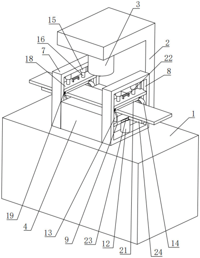
图1为本实施例的结构示意图;Fig. 1 is the structural representation of present embodiment;
图2为本实施例的用于体现固定杆的结构示意图;Fig. 2 is a schematic structural diagram for embodying the fixed rod of the present embodiment;
图3为本实施例的用于体现压柱的结构示意图。FIG. 3 is a schematic structural diagram for embodying a pressure column in this embodiment.
附图标记说明:Explanation of reference signs:
图中:1、工作台;2、固定架;3、冲压机;4、固定板;5、下模具;6、上模具;7、安装板;8、凹槽;9、第一板;10、第一滚轴;12、气缸;13、第一挡板;14、电机;15、套桶;16、压柱;17、压缩弹簧;18、第二板;19、第二挡板;20、第二滚轴;21、防滑套;22、拉环;23、固定杆;24、放置板。In the figure: 1. workbench; 2. fixed frame; 3. stamping machine; 4. fixed plate; 5. lower mold; 6. upper mold; 7. installation plate; 8. groove; 9. first plate; 10 1, the first roller; 12, the cylinder; 13, the first baffle; 14, the motor; 15, the barrel; 16, the pressure column; 17, the compression spring; 18, the second plate; , the second roller; 21, the anti-skid sleeve; 22, the pull ring; 23, the fixed rod; 24, the placement plate.
具体实施方式detailed description
下面将结合本实用新型实施例中的附图,对本实用新型实施例中的技术方案进行清楚、完整地描述,显然,所描述的实施例仅仅是本实用新型一部分实施例,而不是全部的实施例。基于本实用新型中的实施例,本领域普通技术人员在没有做出创造性劳动前提下所获得的所有其他实施例,都属于本实用新型保护的范围。The technical solutions in the embodiments of the present invention will be clearly and completely described below in conjunction with the accompanying drawings in the embodiments of the present invention. Obviously, the described embodiments are only part of the embodiments of the present invention, not all of them. example. Based on the embodiments of the present utility model, all other embodiments obtained by persons of ordinary skill in the art without making creative efforts belong to the scope of protection of the present utility model.
一种车架板材冲压装置,如图1和图2,包括工作台1以及设置在工作台1上的固定架2,固定架2上设有冲压机3,工作台1设有用于放置加工金属板的固定板4,且固定板4位于冲压机3的下方,固定板4设有用于推动加工金属板在固定板4上进行移动的移动件,工作台1上嵌设有下模具5,冲压机3上设有用于通过与下模具5的配合对加工金属板进行冲压切割的上模具6。A stamping device for a vehicle frame plate, as shown in Figures 1 and 2, includes a workbench 1 and a fixed frame 2 arranged on the workbench 1, the fixed frame 2 is provided with a punching machine 3, and the workbench 1 is provided with a The
如图1和图2,使用人将加工金属板放置在固定板4上,然后通过固定板4上的移动件推动加工金属板在固定板4上进行移动,使得加工金属板的冲压位置位于下模具5与上模具6之间,然后打开冲压机3通过冲压机3上的上模具6与下模具5的配合对加工金属板进行冲压切割加工即可,当加工金属板的第一处冲压位置冲压切割完成后,再通过移动件推动加工金属板在固定板4上进行移动,使得加工金属板的下一处冲压位置位于下模具5与上模具6之间,然后再通过冲压机3上的上模具6与下模具5的配合对加工金属板的下一处冲压位置进行冲压切割加工,此时通过移动件即可便于推动加工金属板移动,从而调整加工金属板的冲压切割位置,使用简单方便。As shown in Figures 1 and 2, the user places the processed metal plate on the
如图1和图2,移动件包括设置在固定板4相对两侧的安装板7,且两个安装板7的一侧均开设有凹槽8,加工金属板一端从两个凹槽8中穿过,两个凹槽8内的相对两侧之间均竖直滑移连接有第一板9,且第一板9的顶端均通过转动件转动连接有与加工金属板底端抵触的第一滚轴10,第一滚轴10水平设置,两个凹槽8的底端槽壁均设有用于推动第一板9竖直上下移动的气缸12,两个安装板7上均设有用于将加工金属板压紧在固定板4上的压紧件,此设置的目的在于使用人将加工金属板的一端从两个凹槽8中穿过,将加工金属板放置在固定板4、第一滚轴10上,然后通过压紧件压紧加工金属板,当需要推动加工金属板在固定板4上进行移动时,使用人只需通过打开气缸12,气缸12的活塞杆推动第一板9带动第一滚轴10、加工金属板向上移动,加工金属板与固定板4分离,然后通过转动件带动第一滚轴10转动,此时即可水平移动加工金属板,当将加工金属板移动至合适位置后,气缸12的活塞杆带动第一板9带动第一滚轴10、加工金属板向下移动,将加工金属板重新放置在固定板4上即可,此时即可调整加工金属板的冲压位置,在加工金属板向上移动与固定板4分离的过程中,压紧件将加工金属板压紧在第一滚轴10上,且压紧件不会影响第一滚轴10带动加工金属板水平移动,使用简单方便。As shown in Figures 1 and 2, the moving part includes
如图1和图2,转动件包括相对设置在第一板9顶端的两个第一挡板13,第一滚轴10转动连接在两个第一挡板13之间,其中一个第一挡板13上设有用于驱动第一滚轴10转动的电机14,加工金属板位于两个第一挡板13之间,此设置的目的在于当需要带动第一滚轴10转动时,使用人只需打开电机14,此时电机14的转动轴带动第一滚轴10转动即可,使用简单方便。As shown in Figures 1 and 2, the rotating member includes two
如图2和图3,压紧件包括设置在凹槽8内顶端槽壁的两个套桶15,且套桶15的桶口朝下,两个套桶15内均竖直滑移连接有压柱16,且压柱16与套桶15的桶底之间设有压缩弹簧17,两个压柱16的底端均延伸至套桶15外并通过第二板18连接,第二板18竖直滑移连接在凹槽8内的相对两侧槽壁之间,第二板18的底端设有两个相对的第二挡板19,且两个第二挡板19之间转动连接有与加工金属板底端抵触的第二滚轴20,第二板18与第一板9平行,此设置的目的在于使用人先拉动第二板18向上移动,压柱16逐渐进入套桶15内,压缩弹簧17被压缩,然后将加工金属板的一端从两个凹槽8中穿过,将加工金属板放置在固定板4、第一滚轴10上,然后放开第二板18,此时被压缩的压缩弹簧17则会推动压柱16逐渐从套桶15内移出,第二板18向下移动,直至第二板18上的第二滚轴20与加工金属板顶端接触并将加工金属板压紧在固定板4上即可,压柱16的顶端始终位于套桶15内,当第二滚轴20与加工金属板顶端接触并将加工金属板压紧在固定板4上,通过压缩弹簧17即可在气缸12的活塞杆推动第一板9带动第一滚轴10、加工金属板向上移动,加工金属板与固定板4分离时,将加工金属板压紧在第一滚轴10上,当转动件带动第一滚轴10转动,水平移动加工金属板时,加工金属板带动第二滚轴20转动,使用简单方便。As shown in Fig. 2 and Fig. 3, the pressing member includes two sets of
如图2和图3,两个第二板18的顶端均设有拉环22,且拉环22位于两个压柱16之间,两个第一板9相互背离的一侧均通过固定杆23水平设有放置板24,且放置板24的顶端设有与加工金属板底端接触的滚珠(图中未给出),此设置的目的在于通过拉环22即可便于使用人拉动第二板18向上移动,通过放置板24即可对加工金属板的两端进行支撑,减少加工金属板两端悬空在固定板4两侧因重力发生弯曲的情况发生,使用简单方便。As shown in Fig. 2 and Fig. 3, the tops of the two
如图2,第二滚轴20与第一滚轴10上均套设有与加工金属板抵触的防滑套21,且防滑套21的内壁与第二滚轴20与第一滚轴10固定连接,此设置的目的在于通过防滑套21即可增加第二滚轴20、第一滚轴10与加工金属板的摩擦阻力,使用简单方便。As shown in Figure 2, the
显然,本领域的技术人员可以对本实用新型进行各种改动和变型而不脱离本实用新型的精神和范围。这样,倘若本实用新型的这些修改和变型属于本实用新型权利要求及其等同技术的范围之内,则本实用新型也意图包含这些改动和变型在内。Obviously, those skilled in the art can make various changes and modifications to the utility model without departing from the spirit and scope of the utility model. In this way, if these modifications and variations of the utility model fall within the scope of the claims of the utility model and equivalent technologies thereof, the utility model is also intended to include these modifications and variations.
Claims (6)
Priority Applications (1)
| Application Number | Priority Date | Filing Date | Title |
|---|---|---|---|
| CN202222729759.6U CN218050028U (en) | 2022-10-17 | 2022-10-17 | Vehicle frame plate stamping device |
Applications Claiming Priority (1)
| Application Number | Priority Date | Filing Date | Title |
|---|---|---|---|
| CN202222729759.6U CN218050028U (en) | 2022-10-17 | 2022-10-17 | Vehicle frame plate stamping device |
Publications (1)
| Publication Number | Publication Date |
|---|---|
| CN218050028U true CN218050028U (en) | 2022-12-16 |
Family
ID=84410096
Family Applications (1)
| Application Number | Title | Priority Date | Filing Date |
|---|---|---|---|
| CN202222729759.6U Expired - Fee Related CN218050028U (en) | 2022-10-17 | 2022-10-17 | Vehicle frame plate stamping device |
Country Status (1)
| Country | Link |
|---|---|
| CN (1) | CN218050028U (en) |
Cited By (2)
| Publication number | Priority date | Publication date | Assignee | Title |
|---|---|---|---|---|
| CN117733022A (en) * | 2023-12-29 | 2024-03-22 | 江苏国越储能科技有限公司 | Profiling conveying device for plate mold |
| CN119608976A (en) * | 2024-12-30 | 2025-03-14 | 无锡新维特精密机械有限公司 | A gasket stamping device for electric vehicle gearbox |
-
2022
- 2022-10-17 CN CN202222729759.6U patent/CN218050028U/en not_active Expired - Fee Related
Cited By (3)
| Publication number | Priority date | Publication date | Assignee | Title |
|---|---|---|---|---|
| CN117733022A (en) * | 2023-12-29 | 2024-03-22 | 江苏国越储能科技有限公司 | Profiling conveying device for plate mold |
| CN119608976A (en) * | 2024-12-30 | 2025-03-14 | 无锡新维特精密机械有限公司 | A gasket stamping device for electric vehicle gearbox |
| CN119608976B (en) * | 2024-12-30 | 2025-09-05 | 无锡新维特精密机械有限公司 | A gasket stamping device for electric vehicle gearbox |
Similar Documents
| Publication | Publication Date | Title |
|---|---|---|
| CN110479847A (en) | A kind of punching workpiece automatic arranging mechanism | |
| CN114872128A (en) | Paper punching die | |
| CN114260367A (en) | Diversified stamping die that fixes a position and user equipment thereof | |
| CN112547925A (en) | New energy automobile stamping part machining forming method | |
| CN211363576U (en) | Fixed adjustable-speed punching machine tool | |
| CN115971343A (en) | Intelligent continuous machining stamping die | |
| CN116441386A (en) | Stamping equipment for metal plate processing | |
| CN213002076U (en) | Stamping die who facilitates use | |
| CN118268445B (en) | Motor rotor punching sheet stamping forming device | |
| CN209649532U (en) | a press | |
| CN118403950A (en) | Plate punching machine | |
| CN215965804U (en) | A pressing device for automobile stamping parts | |
| CN112620445A (en) | Automatic stamping, bending and stacking device | |
| CN216881240U (en) | One-step forming continuous stamping device | |
| CN217251934U (en) | Novel portable metal stamping workpiece device | |
| CN216989392U (en) | Stamping equipment is used in metal product production and processing | |
| CN217223209U (en) | Continuous stamping die for metal stamping | |
| CN211757918U (en) | A accurate stamping device for hardware processing | |
| CN210305461U (en) | Material taking device applied to stamping die | |
| CN213793715U (en) | Iron sheet hole pressing equipment | |
| CN222902291U (en) | A sheet metal processing device capable of automatically ejecting sheet metal parts | |
| CN218340770U (en) | Stamping device for machine manufacturing | |
| CN222742112U (en) | Press machine | |
| CN219520150U (en) | An intelligent CNC punching machine | |
| CN223775761U (en) | A stamping device for hardware mold processing |
Legal Events
| Date | Code | Title | Description |
|---|---|---|---|
| GR01 | Patent grant | ||
| GR01 | Patent grant | ||
| CF01 | Termination of patent right due to non-payment of annual fee |
Granted publication date: 20221216 |
|
| CF01 | Termination of patent right due to non-payment of annual fee |