CN218046355U - Pull-up fitness equipment - Google Patents
Pull-up fitness equipment Download PDFInfo
- Publication number
- CN218046355U CN218046355U CN202220788876.7U CN202220788876U CN218046355U CN 218046355 U CN218046355 U CN 218046355U CN 202220788876 U CN202220788876 U CN 202220788876U CN 218046355 U CN218046355 U CN 218046355U
- Authority
- CN
- China
- Prior art keywords
- plate
- circular
- square
- gear
- rod
- Prior art date
- Legal status (The legal status is an assumption and is not a legal conclusion. Google has not performed a legal analysis and makes no representation as to the accuracy of the status listed.)
- Expired - Fee Related
Links
Images


Landscapes
- Rehabilitation Tools (AREA)
Abstract
本实用新型提供了一种引体向上健身器材,包括支撑板1、倾斜板2、方形操作箱10。本实用新型通过第一圆形杆体同时带动绕线辊与第一齿轮进行转动,从而使第一圆形杆体带动钢丝绳进行缠绕,钢丝绳带动连接限位块与倾斜板向上移动,拉动第一方形板体带动第二齿轮与第一齿轮啮合,当需要对倾斜板的角度下放时,推动第一方形板体带动第二齿轮从第一齿轮上脱离,牵扯拉动绳,带动弧形转动板上的倾斜齿从第一齿轮上脱离,当第一圆形杆体转动失控时,紧急松开拉动绳,弹簧的弹性势能推动弧形转动板上的倾斜齿与第一齿轮紧急锁合,操作简便,角度变换高效,能够帮助中小学生实现从“0”到“1”个的“无死角”全过程锻炼提升体质,运动舒适、自然、安全、高效,运动效果非常显著。
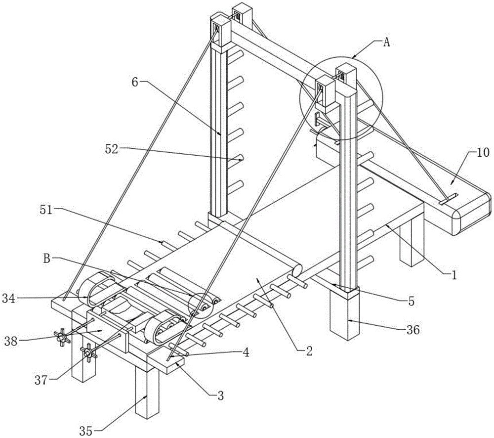
The utility model provides a pull-up fitness equipment, which comprises a support plate 1 , an inclined plate 2 and a square operation box 10 . The utility model simultaneously drives the winding roller and the first gear to rotate through the first circular rod body, so that the first circular rod body drives the steel wire rope to wind, and the steel wire rope drives the connection limit block and the inclined plate to move upward, pulling the first square The plate body drives the second gear to mesh with the first gear. When the angle of the inclined plate needs to be lowered, the first square plate is pushed to drive the second gear to disengage from the first gear, and the pulling rope is pulled to drive the arc-shaped rotating plate. The inclined teeth on the arc-shaped rotating plate are detached from the first gear. When the first circular rod rotates out of control, the pull rope is released urgently. The elastic potential energy of the spring pushes the inclined teeth on the arc-shaped rotating plate to lock with the first gear in an emergency. The operation is simple and convenient. The angle change is efficient, which can help primary and middle school students realize the whole process of "no dead ends" from "0" to "1" to improve their physical fitness. The exercise is comfortable, natural, safe and efficient, and the exercise effect is very significant.
Description
技术领域technical field
本实用新型涉及健身器材技术领域,特别涉及一种引体向上健身器材。The utility model relates to the technical field of fitness equipment, in particular to a pull-up fitness equipment.
背景技术Background technique
青少年的健康体质越来越重视,引体向上是健康体质达标中发展上肢力量的重要项目,但引体向上相对于其它运动,对上肢力量起点要求较高,在中小学体育教学调查中发现存在大量因肥胖、上肢力量弱等原因始终不能实现“0”突破的学生。Teenagers are paying more and more attention to their physical fitness. Pull-ups are an important item for developing upper body strength in reaching healthy physical fitness standards. However, compared with other sports, pull-ups have higher requirements for the starting point of upper body strength. It is found in the survey of physical education in primary and secondary schools that there are A large number of students who have been unable to achieve a "0" breakthrough due to obesity, weak upper body strength and other reasons.
现有的健身器材在使用时,由于健身器材的倾斜板转换角度有限,只能跪姿或坐姿练习,身体无法完全伸直,限制了全身协调用力,且健身器材的倾斜板转换角度有限,特别是倾角在45°以上时头部越发贴近固定支架,几乎无法完成标准动作,该器械换人使用时,通常使用螺栓进行调节固定的握把、支撑板倾角和T型固定装置调节程序繁琐、用时长,不利于提升课堂教学练习密度,且没有紧急安全保险装置,为此,提出一种引体向上健身器材。When the existing fitness equipment is in use, due to the limited conversion angle of the inclined board of the fitness equipment, it can only be practiced in a kneeling or sitting position, and the body cannot be fully straightened, which limits the coordination of the whole body, and the conversion angle of the inclined board of the fitness equipment is limited, especially When the inclination angle is above 45°, the head gets closer to the fixed bracket, and it is almost impossible to complete the standard action. When the device is used by another person, bolts are usually used to adjust the fixed handle, support plate inclination angle and T-shaped fixing device. The adjustment procedures are cumbersome and useless. The time is long, which is not conducive to improving the density of classroom teaching practice, and there is no emergency safety safety device. Therefore, a pull-up fitness equipment is proposed.
实用新型内容Utility model content
有鉴于此,本实用新型实施例希望提供一种引体向上健身器材,以解决或缓解现有技术中存在的技术问题,至少提供一种有益的选择。In view of this, the embodiment of the utility model hopes to provide a pull-up fitness equipment to solve or alleviate the technical problems in the prior art, and at least provide a beneficial option.
本实用新型实施例的技术方案是这样实现的:一种引体向上健身器材,包括支撑板、倾斜板、方形操作箱和圆形板体,所述支撑板的下表面安装有第一固定板,所述支撑板的上表面通过轴承转动连接于所述倾斜板的一侧,所述倾斜板的外侧壁对称安装有两个连接限位块,所述支撑板的后表面安装于所述方形操作箱的前表面,所述方形操作箱内侧壁通过轴承转动连接有第一圆形杆体,所述第一圆形杆体的外侧壁对称安装有两个绕线辊,所述方形操作箱的外侧壁对称开设有两个方形通槽,所述连接限位块的上表面安装有钢丝绳,所述钢丝绳的一端贴合于所述方形通槽的内侧壁且安装于所述绕线辊的外侧壁,所述方形操作箱的内侧壁安装有第二圆形杆体,所述第二圆形杆体的一端开设有圆形通槽,所述圆形通槽贴合有第一方形板体,所述第一方形板体远离所述第二圆形杆体的一端贯穿于所述方形操作箱的内侧壁且安装有把手,所述第一圆形杆体的外侧壁安装有第一齿轮,所述第一方形板体的外侧壁安装有第二齿轮,所述第二齿轮的外侧壁啮合于所述第一齿轮的外侧壁,所述方形操作箱的内侧顶壁通过销轴铰接有弧形转动板,所述弧形转动板的一侧均匀安装有倾斜齿,所述倾斜齿的上表面贴合于所述第一齿轮的外侧壁,所述弧形转动板的另一侧对称安装有两个弹簧,所述弹簧的一端安装于所述方形操作箱的内侧壁,所述方形操作箱的内侧壁安装有承载板,所述承载板的上表面通过轴承转动连接有两个第二导线轮,所述弧形转动板的另一侧安装有拉动绳,所述拉动绳的外侧壁贴合于两个所述第二导线轮相邻的一侧,所述拉动绳的一端贯穿于所述方形操作箱的内侧壁且安装有把手,所述倾斜板的上表面对称安装有两个健身握把。The technical scheme of the embodiment of the utility model is realized in the following way: a pull-up fitness equipment, including a support plate, an inclined plate, a square operation box and a circular plate body, the lower surface of the support plate is equipped with a first fixing plate , the upper surface of the support plate is rotatably connected to one side of the inclined plate through bearings, two connection limit blocks are symmetrically installed on the outer side wall of the inclined plate, and the rear surface of the support plate is installed on the square The front surface of the operation box, the inner side wall of the square operation box is connected with the first circular rod body through bearing rotation, the outer wall of the first circular rod body is symmetrically installed with two winding rollers, the outer side of the square operation box Two square through grooves are symmetrically opened on the wall, and a steel wire rope is installed on the upper surface of the connecting limit block, and one end of the steel wire rope is attached to the inner side wall of the square through groove and installed on the outer side wall of the winding roller , the inner side wall of the square operation box is equipped with a second circular rod body, and one end of the second circular rod body is provided with a circular through groove, and the circular through groove is fitted with a first square plate body, so The end of the first square plate away from the second circular rod penetrates through the inner wall of the square operation box and is equipped with a handle, and the outer wall of the first circular rod is equipped with a first gear. The outer wall of the first square plate body is equipped with a second gear, the outer wall of the second gear is engaged with the outer wall of the first gear, and the inner top wall of the square operation box is hinged with an arc through a pin shaft. Rotating plate, one side of the arc-shaped rotating plate is uniformly equipped with inclined teeth, the upper surface of the inclined teeth is attached to the outer wall of the first gear, and the other side of the arc-shaped rotating plate is symmetrically installed with Two springs, one end of the spring is installed on the inner wall of the square operation box, the inner wall of the square operation box is installed with a bearing plate, and the upper surface of the bearing plate is connected with two second wires through bearing rotation The other side of the arc-shaped rotating plate is equipped with a pulling rope, the outer wall of the pulling rope is attached to the adjacent side of the two second wire pulleys, and one end of the pulling rope runs through the The inner wall of the square operation box is equipped with a handle, and the upper surface of the inclined plate is symmetrically equipped with two fitness handles.
进一步优选的,所述第一固定板的上表面安装有U型支撑架,所述U型支撑架的下表面对称安装有两个第二固定板,所述第二固定板的上表面对称安装有两个U型板体,所述U型板体的内侧壁通过轴承转动连接有第一导线轮,所述钢丝绳的外侧壁贴合于所述第一导线轮的外侧壁,所述圆形通槽的内侧壁相互对称开设有四个滑槽,所述滑槽的内侧壁滑动连接有滑块,所述滑块远离所述滑槽的一侧安装于所述第一方形板体的外侧壁。Further preferably, a U-shaped support frame is installed on the upper surface of the first fixed plate, two second fixed plates are symmetrically installed on the lower surface of the U-shaped support frame, and two second fixed plates are symmetrically installed on the upper surface of the second fixed plate. There are two U-shaped plate bodies, the inner side wall of the U-shaped plate body is connected to the first guide wheel through bearing rotation, the outer side wall of the steel wire rope is attached to the outer side wall of the first guide wheel, and the circular The inner side wall of the through groove is provided with four chute symmetrically with each other, the inner side wall of the chute is slidably connected with a slider, and the side of the slider away from the chute is installed on the side of the first square plate body. outer wall.
进一步优选的,所述第一齿轮的一侧均匀安装有第一三角齿,所述第二齿轮的一侧均匀安装有第二三角齿。Further preferably, first triangular teeth are evenly installed on one side of the first gear, and second triangular teeth are evenly installed on one side of the second gear.
进一步优选的,所述倾斜板的上表面均匀开设有方形凹槽,所述方形凹槽的内侧壁安装有第三圆形杆体,所述第三圆形杆体的外侧壁通过轴承转动连接有圆形橡胶按摩管。Further preferably, the upper surface of the inclined plate is evenly provided with a square groove, the inner side wall of the square groove is installed with a third circular rod body, and the outer wall of the third circular rod body is connected with a circular shaft through a bearing. shaped rubber massage tube.
进一步优选的,所述倾斜板的前表面安装有挡板,所述挡板的前表面对称贯穿有两个第四圆形杆体,所述第四圆形杆体的一端安装有凹槽板体,所述凹槽板体的下表面贴合于圆形橡胶按摩管的外侧顶壁,所述第四圆形杆体的另一端安装有螺纹杆,所述圆形板体的一侧开设有螺纹通孔,所述螺纹通孔的内侧壁螺纹连接于所述螺纹杆的外侧壁,所述圆形板体的外侧壁相互对称安装有四个转动把。Further preferably, a baffle plate is installed on the front surface of the inclined plate, and two fourth circular rod bodies are symmetrically penetrated through the front surface of the baffle plate, and a grooved plate body is installed at one end of the fourth circular rod body, The lower surface of the groove plate fits on the outer top wall of the circular rubber massage tube, the other end of the fourth circular rod is equipped with a threaded rod, and one side of the circular plate is provided with a threaded passage. The inner sidewall of the threaded through hole is threadedly connected to the outer sidewall of the threaded rod, and the outer sidewalls of the circular plate are symmetrically mounted with four rotating handles.
进一步优选的,所述支撑板的上表面开设有方形通孔,所述倾斜板的下表面安装有半圆形箱体,所述半圆形箱体的内侧壁对称安装有两个刻度盘,所述半圆形箱体的外侧壁贯穿通过轴承转动连接有第五圆形杆体,所述第五圆形杆体的两端安装有两个指针,所述第五圆形杆体的外侧底壁安装有铅坠。Further preferably, a square through hole is opened on the upper surface of the support plate, a semicircular box is installed on the lower surface of the inclined plate, and two dials are symmetrically installed on the inner side wall of the semicircular box, The outer wall of the semicircular box runs through a bearing and is connected to a fifth circular rod, two pointers are installed at both ends of the fifth circular rod, and the outer bottom wall of the fifth circular rod is installed There are lead pendants.
进一步优选的,所述支撑板的下表面相互对称安装有四个第一支撑腿,所述第一固定板的下表面对称安装有两个第二支撑腿。Further preferably, four first support legs are symmetrically installed on the lower surface of the support plate, and two second support legs are symmetrically installed on the lower surface of the first fixing plate.
进一步优选的,所述倾斜板的外侧壁均匀安装有第一爬杆,所述第一圆形杆体的一端贯穿于所述方形操作箱的内侧壁且安装有圆形转把。Further preferably, a first climbing rod is uniformly installed on the outer side wall of the inclined plate, and one end of the first circular rod body penetrates through the inner side wall of the square operation box and is installed with a circular handle.
进一步优选的,所述U型支撑架远离所述倾斜板的一侧均匀安装有第二爬杆。Further preferably, second climbing rods are evenly installed on the side of the U-shaped support frame away from the inclined plate.
本实用新型实施例由于采用以上技术方案,其具有以下优点:The embodiment of the utility model has the following advantages due to the adoption of the above technical scheme:
一、本实用新型通过第一圆形杆体同时带动绕线辊与第一齿轮进行转动,从而使第一圆形杆体带动钢丝绳进行缠绕,钢丝绳带动连接限位块与倾斜板向上移动,拉动第一方形板体带动第二齿轮与第一齿轮啮合,当需要对倾斜板的角度下放时,推动第一方形板体带动第二齿轮从第一齿轮上脱离,牵扯拉动绳,带动弧形转动板上的倾斜齿从第一齿轮上脱离,当第一圆形杆体转动失控时,紧急松开拉动绳,弹簧的弹性势能推动弧形转动板上的倾斜齿与第一齿轮紧急锁合,操作简便,角度变换高效,能够帮助中小学生实现从“0”到“1”个的“无死角”全过程锻炼提升体质,运动舒适、自然、安全、高效,运动效果非常显著。1. The utility model simultaneously drives the winding roller and the first gear to rotate through the first circular rod body, so that the first circular rod body drives the steel wire rope to wind, and the steel wire rope drives the connection limit block and the inclined plate to move upward, pulling the first The square plate drives the second gear to mesh with the first gear. When the angle of the inclined plate needs to be lowered, the first square plate is pushed to drive the second gear to disengage from the first gear, and the pulling rope is pulled to drive the arc to rotate. The inclined teeth on the plate are disengaged from the first gear. When the rotation of the first circular rod is out of control, the pull rope is released urgently, and the elastic potential energy of the spring pushes the inclined teeth on the arc-shaped rotating plate to lock with the first gear urgently. It is simple and efficient in changing angles. It can help primary and middle school students to achieve the whole process of exercise from "0" to "1" without dead ends to improve their physical fitness. The exercise is comfortable, natural, safe and efficient, and the exercise effect is very significant.
二、本实用新型通过倾斜板带动半圆形箱体进行移动,从而使铅坠受到重力影响带动第五圆形杆体进行转动,然后第五圆形杆体带动两个指针进行转动,使指针的方向垂直向下移动在刻度盘上,达到快速标识倾斜板的倾斜转动角度,便于不同练习者记忆位置,提高人员使用的准确性及练习密度。2. The utility model drives the semicircular box to move through the inclined plate, so that the lead pendant is affected by gravity to drive the fifth circular rod to rotate, and then the fifth circular rod drives the two pointers to rotate, so that the direction of the pointer Move it vertically downward on the dial to quickly identify the tilting angle of the tilting plate, which is convenient for different practitioners to memorize the position, and improves the accuracy and practice density of personnel.
三、本实用新型通过拿取凹槽板体带动第四圆形杆体贯穿于挡板的一侧,此时人员手持圆形板体移动至第四圆形杆体上的螺纹杆处,然后手持转动把带动圆形板体上的螺纹通孔在螺纹杆内转动,从而方便对凹槽板体的位置进行限位固定,达到跟随人员头部滑动的同时,又能方便大倾斜角锻炼时将凹槽板体取下的目的。3. The utility model drives the fourth circular rod body through one side of the baffle by taking the grooved plate body. At this time, the personnel hold the circular plate body to move to the threaded rod on the fourth circular rod body, and then rotate it by hand. Turn the threaded through hole on the driven circular plate body in the threaded rod, so as to facilitate the limit and fixation of the position of the grooved plate body, so as to follow the sliding of the personnel's head and facilitate the movement of the concave plate when exercising at a large inclination angle. The purpose of removing the groove plate body.
上述概述仅仅是为了说明书的目的,并不意图以任何方式进行限制。除上述描述的示意性的方面、实施方式和特征之外,通过参考附图和以下的详细描述,本实用新型进一步的方面、实施方式和特征将会是容易明白的。The above summary is for illustrative purposes only and is not intended to be limiting in any way. In addition to the illustrative aspects, embodiments and features described above, further aspects, embodiments and features of the present invention will be readily apparent by reference to the drawings and the following detailed description.
附图说明Description of drawings
为了更清楚地说明本申请实施例或现有技术中的技术方案,下面将对实施例或有技术描述中所需要使用的附图作简单地介绍,显而易见地,下面描述中的附图仅仅是本申请的一些实施例,对于本领域普通技术人员来讲,在不付出创造性劳动的前提下,还可以根据这些附图获得其他的附图。In order to more clearly illustrate the technical solutions in the embodiments of the present application or in the prior art, the following will briefly introduce the drawings that need to be used in the embodiments or technical descriptions. Obviously, the drawings in the following description are only For some embodiments of the present application, those of ordinary skill in the art can also obtain other drawings based on these drawings without creative effort.
图1为本实用新型的结构图;Fig. 1 is a structural diagram of the utility model;
图2为本实用新型图1的A区放大结构图;Fig. 2 is the enlarged structural diagram of the A district of Fig. 1 of the utility model;
图3为本实用新型图1的B区放大结构图;Fig. 3 is the enlarged structural diagram of the B area of Fig. 1 of the utility model;
图4为本实用新型的方形操作箱内部结构图;Fig. 4 is the internal structure diagram of the square operation box of the present utility model;
图5为本实用新型的方形操作箱侧剖结构图;Fig. 5 is a side sectional structure diagram of a square operation box of the present utility model;
图6为本实用新型的方形操作箱俯视内部结构图;Fig. 6 is a top view internal structure diagram of the square operation box of the present invention;
图7为本实用新型图6的C区放大结构图;Fig. 7 is the enlarged structural diagram of the C area of Fig. 6 of the utility model;
图8为本实用新型图6的D区放大结构图;Fig. 8 is the enlarged structural diagram of the D area of Fig. 6 of the utility model;
图9为本实用新型的第一齿轮与倾斜齿连接立体结构图;Fig. 9 is a three-dimensional structure diagram of the connection between the first gear and the inclined teeth of the present invention;
图10为本实用新型的后视结构图;Fig. 10 is the rear view structural diagram of the utility model;
图11为本实用新型的凹槽板体与第四圆形杆体连接立体结构图;Fig. 11 is a three-dimensional structure diagram of the connection between the grooved plate body and the fourth circular rod body of the present invention;
图12为本实用新型的挡板于圆形板体内部结构图;Fig. 12 is a diagram of the internal structure of the baffle plate in the circular plate body of the present invention;
图13为本实用新型的侧剖结构图;Fig. 13 is a side sectional structure diagram of the utility model;
图14为本实用新型的半圆形箱体内部结构图。Fig. 14 is a diagram of the internal structure of the semicircular box of the present invention.
附图标记:1、支撑板;2、倾斜板;3、连接限位块;4、钢丝绳;5、第一固定板;6、U型支撑架;7、第二固定板;8、U型板体;9、第一导线轮;10、方形操作箱;11、方形通槽;12、第一圆形杆体;13、绕线辊;15、第一齿轮;16、第一方形板体;17、第二齿轮;18、弧形弧形转动板;19、倾斜齿;20、弹簧;21、拉动绳;22、承载板;23、第二导线轮;24、第二圆形杆体;25、圆形通槽;26、滑槽;27、滑块;28、第一三角齿;29、第二三角齿;30、圆形转把;31、方形凹槽;32、第三圆形杆体;33、圆形橡胶按摩管;34、健身握把;35、第一支撑腿;36、第二支撑腿;37、凹槽板体;38、挡板;40、第四圆形杆体;41、圆形板体;42、螺纹通孔;43、螺纹杆;44、转动把;45、方形通孔;46、半圆形箱体;47、刻度盘;48、指针;49、第五圆形杆体;50、铅坠;51、第一爬杆;52、第二爬杆。Reference signs: 1, support plate; 2, inclined plate; 3, connection limit block; 4, steel wire rope; 5, first fixed plate; 6, U-shaped support frame; 7, second fixed plate; 8, U-shaped Plate body; 9. The first guide wheel; 10. Square operation box; 11. Square through slot; 12. The first circular rod body; 13. Winding roller; 15. The first gear; 16. The first square plate body ; 17, the second gear; 18, arc-shaped rotating plate; 19, inclined teeth; 20, spring; 21, pulling rope; 22, bearing plate; 23, the second guide wheel; 25. Circular through slot; 26. Chute; 27. Slider; 28. First triangular tooth; 29. Second triangular tooth; 30. Round handle; 31. Square groove; 32. Third circular Rod body; 33, circular rubber massage tube; 34, fitness grip; 35, first support leg; 36, second support leg; 37, groove plate body; 38, baffle plate; 40, fourth circular rod body; 41. Circular plate body; 42. Threaded through hole; 43. Threaded rod; 44. Turn handle; 45. Square through hole; 46. Semicircular box; 47. Dial plate; 48. Pointer; 49. Fifth Circular pole body; 50, lead pendant; 51, the first climbing pole; 52, the second climbing pole.
具体实施方式detailed description
在下文中,仅简单地描述了某些示例性实施例。正如本领域技术人员可认识到的那样,在不脱离本实用新型的精神或范围的情况下,可通过各种不同方式修改所描述的实施例。因此,附图和描述被认为本质上是示例性的而非限制性的。In the following, only some exemplary embodiments are briefly described. As those skilled in the art would realize, the described embodiments may be modified in various different ways, all without departing from the spirit or scope of the present invention. Accordingly, the drawings and descriptions are to be regarded as illustrative in nature and not restrictive.
下面结合附图对本实用新型的实施例进行详细说明。Embodiments of the utility model will be described in detail below in conjunction with the accompanying drawings.
实施例一Embodiment one
如图1-14所示,本发明实施例提供了一种引体向上健身器材,包括支撑板1、倾斜板2、方形操作箱10和圆形板体41,支撑板1的下表面安装有第一固定板5,支撑板1的上表面通过轴承转动连接于倾斜板2的一侧,倾斜板2的外侧壁对称安装有两个连接限位块3,支撑板1的后表面安装于方形操作箱10的前表面,方形操作箱10内侧壁通过轴承转动连接有第一圆形杆体12,第一圆形杆体12的外侧壁对称安装有两个绕线辊13,方形操作箱10的外侧壁对称开设有两个方形通槽11,连接限位块3的上表面安装有钢丝绳4,钢丝绳4的一端贴合于方形通槽11的内侧壁且安装于绕线辊13的外侧壁,方形操作箱10的内侧壁安装有第二圆形杆体24,第二圆形杆体24的一端开设有圆形通槽25,圆形通槽25贴合有第一方形板体16,第一方形板体16远离第二圆形杆体24的一端贯穿于方形操作箱10的内侧壁且安装有把手,第一圆形杆体12的外侧壁安装有第一齿轮15,第一方形板体16的外侧壁安装有第二齿轮17,第二齿轮17的外侧壁啮合于第一齿轮15的外侧壁,方形操作箱10的内侧顶壁通过销轴铰接有弧形转动板18,弧形转动板18的一侧均匀安装有倾斜齿19,倾斜齿19的上表面贴合于第一齿轮15的外侧壁,弧形转动板18的另一侧对称安装有两个弹簧20,弹簧20的一端安装于方形操作箱10的内侧壁,方形操作箱10的内侧壁安装有承载板22,承载板22的上表面通过轴承转动连接有两个第二导线轮23,弧形转动板18的另一侧安装有拉动绳21,拉动绳21的外侧壁贴合于两个第二导线轮23相邻的一侧,拉动绳21的一端贯穿于方形操作箱10的内侧壁且安装有把手,倾斜板2的上表面对称安装有两个健身握把34。As shown in Figures 1-14, the embodiment of the present invention provides a pull-up fitness equipment, including a
在一个实施例中,第一固定板5的上表面安装有U型支撑架6,U型支撑架6的下表面对称安装有两个第二固定板7,第二固定板7的上表面对称安装有两个U型板体8,U型板体8的内侧壁通过轴承转动连接有第一导线轮9,钢丝绳4的外侧壁贴合于第一导线轮9的外侧壁,圆形通槽25的内侧壁相互对称开设有四个滑槽26,滑槽26的内侧壁滑动连接有滑块27,滑块27远离滑槽26的一侧安装于第一方形板体16的外侧壁,通过U型支撑架6的设置,方便固定第二固定板7的位置,其中U型板体8的设置,既能固定第一导线轮9的位置,又能防止钢丝绳4从第一导线轮9上脱落。In one embodiment, a
在一个实施例中,第一齿轮15的一侧均匀安装有第一三角齿28,第二齿轮17的一侧均匀安装有第二三角齿29,通过第一三角齿28和第二三角齿29的设置,用于方便第一齿轮15与第二齿轮17进行啮合,提高卡和的准确性。In one embodiment, first
实施例二Embodiment two
基于实施例一的技术方案,进一步的:倾斜板2的上表面均匀开设有方形凹槽31,方形凹槽31的内侧壁安装有第三圆形杆体32,第三圆形杆体32的外侧壁通过轴承转动连接有圆形橡胶按摩管33,通过第三圆形杆体32与圆形橡胶按摩管33的设置,既能起到支撑身体练习时无阻力向上滑动作用,又能对人体背部穴位进行按摩,提高肌肉放松度和养生保健效果。Based on the technical solution of
实施例三Embodiment Three
基于实施例一的技术方案,进一步的:倾斜板2的前表面安装有挡板38,挡板38的前表面对称贯穿有两个第四圆形杆体40,第四圆形杆体40的一端安装有凹槽板体37,凹槽板体37的下表面贴合于圆形橡胶按摩管33的外侧顶壁,第四圆形杆体40的另一端安装有螺纹杆43,圆形板体41的一侧开设有螺纹通孔42,螺纹通孔42的内侧壁螺纹连接于螺纹杆43的外侧壁,圆形板体41的外侧壁相互对称安装有四个转动把44,通过手持转动把44带动圆形板体41上的螺纹通孔42在螺纹杆43内转动,从而方便对凹槽板体37的位置进行限位固定。Based on the technical solution of
实施例四Embodiment Four
基于实施例一的技术方案,进一步的:支撑板1的上表面开设有方形通孔45,倾斜板2的下表面安装有半圆形箱体46,半圆形箱体46的内侧壁对称安装有两个刻度盘47,半圆形箱体46的外侧壁贯穿通过轴承转动连接有第五圆形杆体49,第五圆形杆体49的两端安装有两个指针48,第五圆形杆体49的外侧底壁安装有铅坠50,通过倾斜板2带动半圆形箱体46进行移动,从而使铅坠50受到重力影响带动第五圆形杆体49进行转动,然后第五圆形杆体49带动两个指针48进行转动,其中方形通孔45的设置,方便半圆形箱体46进行嵌入移动。Based on the technical solution of
实施例五Embodiment five
基于实施例一的技术方案,进一步的:支撑板1的下表面相互对称安装有四个第一支撑腿35,第一固定板5的下表面对称安装有两个第二支撑腿36,通过第一支撑腿35的设置,既能抬高支撑板1的高度,又能稳定支撑板1的位置,其中第二支撑腿36的设置,既能支撑第一固定板5的位置,又能进一步支撑支撑板1的位置。Based on the technical solution of
在一个实施例中,倾斜板2的外侧壁均匀安装有第一爬杆51,第一圆形杆体12的一端贯穿于方形操作箱10的内侧壁且安装有圆形转把30,通过第一爬杆51的设置,用于辅助人员进行运动前后上下倾斜板2,其中圆形转把30的设置,用于辅助第一圆形杆体12进行转动。In one embodiment, a
在一个实施例中,其特征在于:U型支撑架6远离倾斜板2的一侧均匀安装有第二爬杆52,通过第二爬杆52的设置,用于辅助辅助人员进行上下倾斜板2。In one embodiment, it is characterized in that a
本实用新型在工作时:需要对2的角度进行改变时,只需手持圆形转把30带动第一圆形杆体12进行转动,第一圆形杆体12同时带动绕线辊13与第一齿轮15进行转动,在第一齿轮15转动时,通过弹簧20将弧形转动板18上的倾斜齿19推动贴合在第一齿轮15的外侧壁,由于倾斜齿19为斜齿,倾斜齿19不妨碍第一齿轮15的正向转动,从而使第一圆形杆体12带动钢丝绳4进行缠绕,然后钢丝绳4通过第一导线轮9改变拉动角度,其中U型板体8用于防止钢丝绳4从第一导线轮9上脱离,钢丝绳4带动连接限位块3向上移动,连接限位块3带动倾斜板2进行转动角度,此时通过倾斜板2带动半圆形箱体46进行移动,从而使铅坠50受到重力影响带动第五圆形杆体49进行转动,然后第五圆形杆体49带动两个指针48进行转动,使指针48的方向垂直向下移动在刻度盘47上,进而显示倾斜板2的倾斜转动角度,当倾斜板2转动至练习者想要的角度时,此时操作把手带动第一方形板体16在第二圆形杆体24内滑动,从而使第一方形板体16带动第二齿轮17移动至第一齿轮15上,其中第二三角齿29与第一三角齿28进行辅助第二齿轮17与第一齿轮15进行啮合,当人员需要进行健身时,通过拿取凹槽板体37带动第四圆形杆体40贯穿于挡板38的一侧,此时人员手持第圆形板体41移动至第四圆形杆体40上的螺纹杆43处,然后手持转动把44带动圆形板体41上的螺纹通孔42在螺纹杆43内转动,从而方便对凹槽板体37的位置进行限位固定,只需通过攀爬第一爬杆51和第二爬杆52上至倾斜板2上,人员手握健身握把34处后,将头部放置凹槽板体37内,在人员进行锻炼时,多个圆形橡胶按摩管33跟随背部转动按摩,圆形橡胶按摩管33的设置在臀部往上,然后头部带动凹槽板体37进行同步移动,辅助人员进行锻炼,此时当人员健身完毕后,只需人员通过第一爬杆51和第二爬杆52方便练习者安全从倾斜板2上下来,此时若需要对倾斜板2的位置放平时,只需要手持把手推动第一方形板体16上的第二齿轮17从第一齿轮15上脱离,然后手持把手带动拉动绳21在第二导线轮23上拉动,从而使拉动绳21带动弧形转动板18上的倾斜齿19从第一齿轮15上脱离,从而方便人员手持圆形转把30带动第一圆形杆体12带动绕线辊13进行反转,使绕线辊13上的钢丝绳4进行放线,从而方便将倾斜板2进行放平,当圆形转把30从人员手中脱离时,只需松下拉动绳21时,弹簧20的弹性势能推动弧形转动板18上的倾斜齿19紧急锁合第一齿轮15,从而对第一圆形杆体12的位置进行紧急限位,提高使用的安全性。When the utility model is working: when it is necessary to change the angle of 2, it is only necessary to hold the
以上所述,仅为本实用新型的具体实施方式,但本实用新型的保护范围并不局限于此,任何熟悉本技术领域的技术人员在本实用新型揭露的技术范围内,可轻易想到其各种变化或替换,这些都应涵盖在本实用新型的保护范围之内。因此,本实用新型的保护范围应以所述权利要求的保护范围为准。The above is only a specific embodiment of the utility model, but the scope of protection of the utility model is not limited thereto, and any person familiar with the technical field can easily think of its various Any changes or replacements should be covered within the protection scope of the present utility model. Therefore, the protection scope of the present utility model should be based on the protection scope of the claims.
Claims (9)
Priority Applications (1)
| Application Number | Priority Date | Filing Date | Title |
|---|---|---|---|
| CN202220788876.7U CN218046355U (en) | 2022-04-06 | 2022-04-06 | Pull-up fitness equipment |
Applications Claiming Priority (1)
| Application Number | Priority Date | Filing Date | Title |
|---|---|---|---|
| CN202220788876.7U CN218046355U (en) | 2022-04-06 | 2022-04-06 | Pull-up fitness equipment |
Publications (1)
| Publication Number | Publication Date |
|---|---|
| CN218046355U true CN218046355U (en) | 2022-12-16 |
Family
ID=84414014
Family Applications (1)
| Application Number | Title | Priority Date | Filing Date |
|---|---|---|---|
| CN202220788876.7U Expired - Fee Related CN218046355U (en) | 2022-04-06 | 2022-04-06 | Pull-up fitness equipment |
Country Status (1)
| Country | Link |
|---|---|
| CN (1) | CN218046355U (en) |
Cited By (1)
| Publication number | Priority date | Publication date | Assignee | Title |
|---|---|---|---|---|
| CN114618129A (en) * | 2022-04-06 | 2022-06-14 | 胡虎 | Pull-up fitness equipment |
-
2022
- 2022-04-06 CN CN202220788876.7U patent/CN218046355U/en not_active Expired - Fee Related
Cited By (1)
| Publication number | Priority date | Publication date | Assignee | Title |
|---|---|---|---|---|
| CN114618129A (en) * | 2022-04-06 | 2022-06-14 | 胡虎 | Pull-up fitness equipment |
Similar Documents
| Publication | Publication Date | Title |
|---|---|---|
| CN112023346A (en) | Traditional chinese medical science old nursing is with recovered device of taking exercise | |
| CN206198572U (en) | A kind of waist abdomen training apparatus | |
| CN108654122A (en) | A kind of hurdle bracket for sports training | |
| CN111111105B (en) | A lower limb rehabilitation exercise device for preventing blood flow stagnation | |
| CN110624214A (en) | A kind of supine abdomen tightening apparatus for physical exercise | |
| CN214861023U (en) | Breathing trainer moving support | |
| CN110639162A (en) | Body-building device and method based on motion monitoring and analysis | |
| CN114618129A (en) | Pull-up fitness equipment | |
| CN210020996U (en) | A college sports indoor fitness equipment | |
| CN214388726U (en) | Physical training device for physical education teaching | |
| CN213589654U (en) | Rehabilitation upper limb pushing trainer | |
| CN213491805U (en) | Belly weight-reducing training device | |
| CN111282249B (en) | Yoga body-building auxiliary equipment | |
| CN210751136U (en) | Recovered upper limbs exerciser of middle-aged and old | |
| CN212369505U (en) | An aerobic exercise training device for upper limbs | |
| CN209630535U (en) | A kind of Neurology family rehabilitation training device | |
| CN211302008U (en) | A new type of Taijiquan practice device | |
| CN218923706U (en) | An arm joint rehabilitation device | |
| CN110201354A (en) | A kind of auxiliary device for athletic training | |
| CN222605346U (en) | A pedal-type barbell rack | |
| CN219743816U (en) | An exercise recovery device | |
| CN210992778U (en) | Gym equipment special deglutinous bright tube | |
| CN218305965U (en) | Pull-up training frame for physical training | |
| CN218129746U (en) | Cardiovascular disease patient tempers nursing device | |
| CN221579627U (en) | A combined rehabilitation limb exerciser |
Legal Events
| Date | Code | Title | Description |
|---|---|---|---|
| GR01 | Patent grant | ||
| GR01 | Patent grant | ||
| CF01 | Termination of patent right due to non-payment of annual fee | ||
| CF01 | Termination of patent right due to non-payment of annual fee |
Granted publication date: 20221216 |