CN218045372U - An auxiliary device for intraoperative observation of plastic surgery patients - Google Patents
An auxiliary device for intraoperative observation of plastic surgery patients Download PDFInfo
- Publication number
- CN218045372U CN218045372U CN202221020657.0U CN202221020657U CN218045372U CN 218045372 U CN218045372 U CN 218045372U CN 202221020657 U CN202221020657 U CN 202221020657U CN 218045372 U CN218045372 U CN 218045372U
- Authority
- CN
- China
- Prior art keywords
- threaded rod
- mirror
- fixedly installed
- drive
- rod
- Prior art date
- Legal status (The legal status is an assumption and is not a legal conclusion. Google has not performed a legal analysis and makes no representation as to the accuracy of the status listed.)
- Expired - Fee Related
Links
Images


Landscapes
- Accommodation For Nursing Or Treatment Tables (AREA)
Abstract
一种整形患者术中观察辅助装置,包括:底座,底座的表面固定安装有驱动箱,驱动箱的内部转动连接有第一螺纹杆,第一螺纹杆的一端贯穿驱动箱延伸至外部,第一螺纹杆的贯穿端螺纹连接有移动套筒,驱动箱的内部设置有蜗轮,蜗轮固定安装第一螺纹杆的表面,本实用新型具有以下优点:医护人员通过转动蜗杆驱动移动套筒的位置,从而对镜面进行竖直高度位置调节,再通过转动第二螺纹杆带动导向块在导向盒水平移动,带动镜面进行水平位置调节,并且通过转动支撑架带动镜面进行水平旋转,达到对镜面旋转角度调节,镜面再通过两个连接轴连接,可以对镜面进行正反转,达到对镜面多角度调节,便于患者从不同位置观察整形效果。
An observation auxiliary device for plastic surgery patients, comprising: a base, a drive box is fixedly installed on the surface of the base, a first threaded rod is connected to the inside of the drive box for rotation, one end of the first threaded rod extends through the drive box to the outside, the first The penetrating end of the threaded rod is threadedly connected with a moving sleeve, and the inside of the drive box is provided with a worm gear, which is fixedly installed on the surface of the first threaded rod. The utility model has the following advantages: medical personnel drive the position of the moving sleeve by rotating the worm, thereby Adjust the vertical height position of the mirror surface, and then drive the guide block to move horizontally in the guide box by turning the second threaded rod, drive the mirror surface to adjust the horizontal position, and drive the mirror surface to rotate horizontally by rotating the support frame, so as to adjust the rotation angle of the mirror surface. The mirror surface is connected by two connecting shafts, and the mirror surface can be turned forward and backward to achieve multi-angle adjustment of the mirror surface, which is convenient for patients to observe the plastic surgery effect from different positions.
Description
技术领域technical field
本实用涉及医疗器械技术领域,具体涉及一种整形患者术中观察辅助装置。The utility model relates to the technical field of medical instruments, in particular to an observation auxiliary device for plastic surgery patients.
背景技术Background technique
整形的治疗范围主要是皮肤、肌肉及骨骼等创伤、疾病、先天性或后天性组织或器官的缺陷与畸形。治疗包括修复与再造两个内容,以手术方法进行自体的各种组织移植,也可采用异体、异种组织等改善或恢复生理功能和外貌。The scope of plastic surgery is mainly skin, muscle and bone trauma, disease, congenital or acquired defects and deformities of tissues or organs. Treatment includes repair and reconstruction. Various autologous tissue transplants can be performed by surgical methods, and allogenic or heterogeneous tissues can also be used to improve or restore physiological functions and appearance.
现有的整形患者在手术的过程中会通过镜面观察整形效果,但现有的镜面只是固定在支撑架表面,镜面不能进行位置调节,镜面观察范围有限,从而不便于患者从不同位置观察整形效果。Existing plastic surgery patients will observe the plastic surgery effect through the mirror during the operation, but the existing mirror is only fixed on the surface of the support frame, the position of the mirror cannot be adjusted, and the mirror observation range is limited, which makes it inconvenient for patients to observe the plastic surgery effect from different positions .
实用新型内容Utility model content
本实用新型要解决的技术问题是现有的整形患者在手术的过程中会通过镜面观察整形效果,但现有的镜面只是固定在支撑架表面,镜面不能进行位置调节,镜面观察范围有限,从而不便于患者从不同位置观察整形效果,现提供一种整形患者术中观察辅助装置,医护人员通过转动蜗杆驱动移动套筒的位置,从而对镜面进行竖直高度位置调节,再通过转动第二螺纹杆带动导向块在导向盒水平移动,带动镜面进行水平位置调节,并且通过转动支撑架带动镜面进行水平旋转,达到对镜面旋转角度调节,镜面再通过两个连接轴连接,可以对镜面进行正反转,达到对镜面多角度调节,便于患者从不同位置观察整形效果。The technical problem to be solved by the utility model is that the existing plastic surgery patients can observe the plastic surgery effect through the mirror during the operation, but the existing mirror is only fixed on the surface of the support frame, the position of the mirror cannot be adjusted, and the scope of observation of the mirror is limited. It is inconvenient for patients to observe the plastic surgery effect from different positions. Now we provide an auxiliary observation device for plastic surgery patients. The medical staff drives the position of the moving sleeve by turning the worm to adjust the vertical height position of the mirror surface, and then rotates the second thread to adjust the position of the sleeve. The rod drives the guide block to move horizontally in the guide box, drives the mirror to adjust the horizontal position, and rotates the support frame to drive the mirror to rotate horizontally to adjust the rotation angle of the mirror. The mirror is connected by two connecting shafts, and the mirror can be reversed Turn to achieve multi-angle adjustment of the mirror surface, which is convenient for patients to observe the plastic surgery effect from different positions.
本实用新型解决技术问题采用的技术方案是:本实用新型一种整形患者术中观察辅助装置,包括:底座,所述底座的表面固定安装有驱动箱,所述驱动箱的内部转动连接有第一螺纹杆,所述第一螺纹杆的一端贯穿驱动箱延伸至外部,所述第一螺纹杆的贯穿端螺纹连接有移动套筒,所述驱动箱的内部设置有蜗轮,所述蜗轮固定安装第一螺纹杆的表面,所述蜗轮的表面一侧啮合连接有蜗杆,所述蜗杆的两端转动连接驱动箱的内部。The technical scheme adopted by the utility model to solve the technical problem is: the utility model is an observation auxiliary device for plastic surgery patients, comprising: a base, a drive box is fixedly installed on the surface of the base, and the inside of the drive box is rotationally connected with a second A threaded rod, one end of the first threaded rod extends through the drive box to the outside, the penetrating end of the first threaded rod is screwed with a moving sleeve, the inside of the drive box is provided with a worm wheel, and the worm wheel is fixedly installed The surface of the first threaded rod is meshed with a worm on one side of the surface of the worm wheel, and the two ends of the worm are rotatably connected to the inside of the drive box.
作为本实用新型的一种优选技术方案,所述移动套筒的表面两侧固定安装有定位板,所述定位板的内部滑动插接有定位杆,所述定位杆固定安装底座的表面,通过定位杆滑动插接定位板的内部,从而定位杆对移动套筒的移动提供限位的作用。As a preferred technical solution of the present invention, positioning plates are fixedly installed on both sides of the surface of the moving sleeve, and a positioning rod is slidably inserted into the inside of the positioning plate, and the positioning rod is fixed on the surface of the mounting base. The positioning rod is slidably plugged into the inside of the positioning plate, so that the positioning rod provides a position-limiting effect on the movement of the moving sleeve.
作为本实用新型的一种优选技术方案,所述移动套筒的顶部固定安装有导向盒,所述导向盒的内部转动连接有第二螺纹杆,所述第二螺纹杆的表面螺纹连接有导向块,所述导向块的底部滑动插接有横杆,所述横杆的两端固定安装有导向盒的内部,通过第二螺纹杆转动带动导向块在导向盒的内部进行水平移动,同时横杆对导向块的移动提供支撑和限位的作用。As a preferred technical solution of the present utility model, a guide box is fixedly installed on the top of the moving sleeve, and a second threaded rod is connected to the inside of the guide box, and the surface of the second threaded rod is threadedly connected with a guide box. The bottom of the guide block is slidingly inserted with a cross bar, and the two ends of the cross bar are fixedly installed inside the guide box, and the second threaded rod rotates to drive the guide block to move horizontally inside the guide box, and at the same time The rod provides support and limit to the movement of the guide block.
作为本实用新型的一种优选技术方案,所述导向块的顶部转动连接有转动轴,所述转动轴的顶部固定安装有支撑架,所述支撑架的两侧转动连接有连接轴,两个所述连接轴的一端固定连接同一个镜面,通过转动支撑架带动镜面进行水平旋转,达到对镜面旋转角度调节,镜面再通过两个连接轴连接,可以对镜面进行正反转。As a preferred technical solution of the present utility model, the top of the guide block is rotatably connected with a rotating shaft, the top of the rotating shaft is fixedly mounted with a support frame, and the two sides of the support frame are rotatably connected with a connecting shaft, two One end of the connecting shaft is fixedly connected to the same mirror, and the rotating support frame drives the mirror to rotate horizontally to adjust the rotation angle of the mirror.
作为本实用新型的一种优选技术方案,所述镜面的表面固定安装有LED光圈,通过镜面表面安装的LED光圈,所述镜面侧面固定安装有调节杆,所述调节杆的表面套接有硅胶套,通过对硅胶套表面进行消毒杀菌,同时医护人员可以通过调节杆移动镜面,方便强光环境下患者依旧通过镜面观察清楚。As a preferred technical solution of the present invention, the surface of the mirror is fixedly equipped with an LED aperture, and through the LED aperture installed on the surface of the mirror, an adjustment rod is fixedly installed on the side of the mirror, and the surface of the adjustment rod is sleeved with a silica gel By disinfecting and sterilizing the surface of the silicone sleeve, at the same time, medical staff can move the mirror through the adjustment lever, so that patients can still observe clearly through the mirror in a strong light environment.
本实用新型具有以下优点:医护人员通过转动蜗杆蜗轮带动第一螺纹杆进行转动,从而调节移动套筒的位置,进而对镜面进行竖直高度位置调节,再通过转动第二螺纹杆带动导向块在导向盒水平移动,带动镜面进行水平位置调节,并且通过转动支撑架带动镜面进行水平旋转,达到对镜面旋转角度调节,镜面再通过两个连接轴连接,可以对镜面进行正反转,达到对镜面多角度调节,便于患者从不同位置观察整形效果,同时通过镜面表面安装的LED光圈,方便强光环境下患者依旧通过镜面观察清楚。The utility model has the following advantages: the medical personnel rotate the first threaded rod by turning the worm gear to adjust the position of the moving sleeve, and then adjust the vertical height position of the mirror surface, and then drive the guide block by rotating the second threaded rod. The guide box moves horizontally, drives the mirror to adjust the horizontal position, and rotates the support frame to drive the mirror to rotate horizontally to adjust the rotation angle of the mirror. Multi-angle adjustment is convenient for patients to observe the plastic surgery effect from different positions. At the same time, through the LED aperture installed on the mirror surface, it is convenient for patients to observe clearly through the mirror in a strong light environment.
附图说明Description of drawings
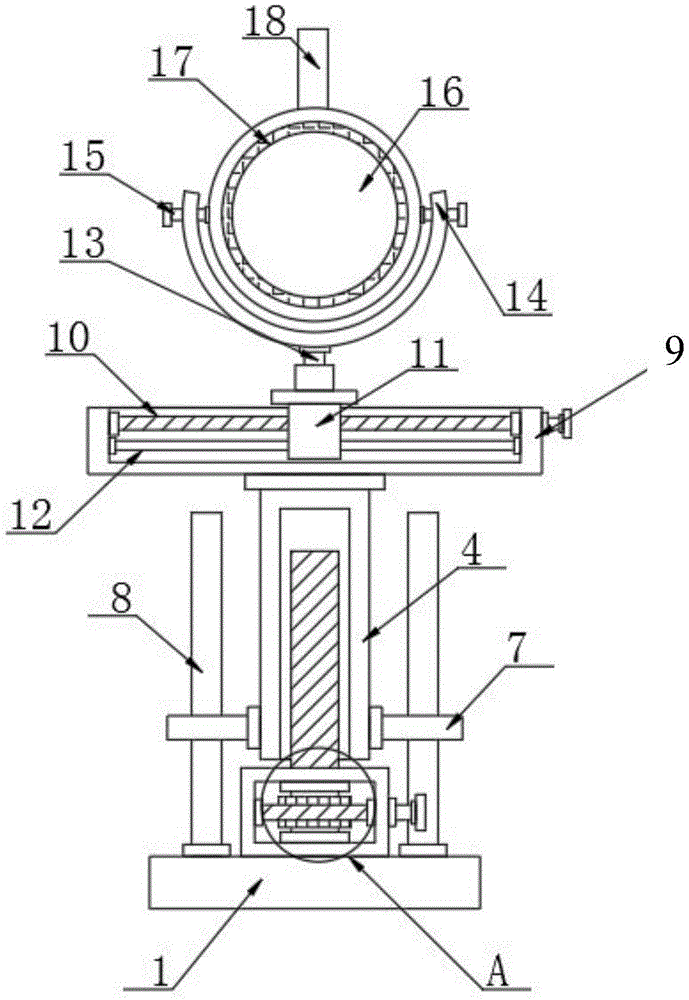
图1是本实用新型一优选实施例的一种整形患者术中观察辅助装置的整体结构示意图;Fig. 1 is a schematic diagram of the overall structure of an intraoperative observation auxiliary device for plastic surgery patients in a preferred embodiment of the present invention;
图2是本实用新型一优选实施例的一种整形患者术中观察辅助装置图1的A处放大示意图;Fig. 2 is an enlarged schematic diagram of A in Fig. 1 of an intraoperative observation auxiliary device for plastic surgery patients according to a preferred embodiment of the present invention;
图3是本实用新型一优选实施例的一种整形患者术中观察辅助装置底座和移动套筒的立体示意图。Fig. 3 is a three-dimensional schematic diagram of a base and a moving sleeve of an observation auxiliary device for plastic surgery patients in a preferred embodiment of the present invention.
附图标记说明:1、底座;2、驱动箱;3、第一螺纹杆;4、移动套筒;5、蜗轮;6、蜗杆;7、定位板;8、定位杆;9、导向盒;10、第二螺纹杆;11、导向块;12、横杆;13、转动轴;14、支撑架;15、连接轴;16、镜面;17、LED光圈;18、调节杆。Description of reference signs: 1, base; 2, drive box; 3, first threaded rod; 4, moving sleeve; 5, worm wheel; 6, worm; 7, positioning plate; 8, positioning rod; 9, guide box; 10. Second threaded rod; 11. Guide block; 12. Cross bar; 13. Rotation shaft; 14. Support frame; 15. Connecting shaft; 16. Mirror surface; 17. LED aperture; 18. Adjusting rod.
具体实施方式detailed description
下面将结合附图对本实用新型的技术方案进行清楚、完整地描述。在本实用新型的描述中,需要说明的是,术语“中心”、“上”、“下”、“左”、“右”、“竖直”、“水平”、“内”、“外”等指示的方位或位置关系为基于附图所示的方位或位置关系,仅是为了便于描述本实用新型和简化描述,而不是指示或暗示所指的装置或元件必须具有特定的方位、以特定的方位构造和操作,因此不能理解为对本实用新型的限制。此外,术语“第一”、“第二”、“第三”仅用于描述目的,而不能理解为指示或暗示相正对地重要性。The technical solution of the utility model will be clearly and completely described below in conjunction with the accompanying drawings. In the description of the present utility model, it should be noted that the terms "center", "upper", "lower", "left", "right", "vertical", "horizontal", "inner", "outer" The orientation or positional relationship indicated by etc. is based on the orientation or positional relationship shown in the drawings, which is only for the convenience of describing the utility model and simplifying the description, rather than indicating or implying that the device or element referred to must have a specific orientation, use a specific The azimuth structure and operation, therefore can not be construed as the limitation of the present utility model. In addition, the terms "first", "second", and "third" are used for descriptive purposes only, and should not be construed as indicating or implying relative importance.
在本实用新型的描述中,需要说明的是,除非另有明确的规定和限定,术语“安装”、“相连”、“连接”应做广义理解,例如,可以是固定连接,也可以是可拆卸连接,或一体地连接;可以是机械连接,也可以是电连接;可以是直接相连,也可以通过中间媒介间接相连,可以是两个元件内部的连通。对于本领域的普通技术人员而言,可以具体情况理解上述术语在本实用新型中的具体含义。In the description of the present utility model, it should be noted that, unless otherwise clearly stipulated and limited, the terms "installation", "connection" and "connection" should be understood in a broad sense, for example, it can be a fixed connection or a flexible connection. Detachable connection, or integral connection; it can be mechanical connection or electrical connection; it can be direct connection or indirect connection through an intermediary, and it can be the internal communication of two components. Those of ordinary skill in the art can understand the specific meanings of the above terms in the present utility model in specific situations.
下面结合附图对本实用新型作进一步说明。Below in conjunction with accompanying drawing, the utility model is further described.
请结合参阅图1-3,本实用新型一种整形患者术中观察辅助装置,包括:底座1,底座1的表面固定安装有驱动箱2,驱动箱2的内部转动连接有第一螺纹杆3,第一螺纹杆3的一端贯穿驱动箱2延伸至外部,第一螺纹杆3的贯穿端螺纹连接有移动套筒4,驱动箱2的内部设置有蜗轮5,蜗轮5固定安装第一螺纹杆3的表面,蜗轮5的表面一侧啮合连接有蜗杆6,蜗杆6的两端转动连接驱动箱2的内部,医护人员通过转动蜗杆6带动蜗轮5进行转动,从而蜗轮5转动带动第一螺纹杆3进行旋转,第一螺纹杆3转动带动移动套筒4进行升降,进而对镜面16进行竖直高度位置调节。Please refer to Figures 1-3, the utility model is an auxiliary observation device for plastic surgery patients, including: a base 1, a
其中,定位板7固定安装移动套筒4的表面两侧,定位杆8滑动插接定位板7的内部,底座1的表面固定安装定位杆8的底端,通过定位杆8滑动插接定位板7的内部,从而定位杆8对移动套筒4的移动提供限位的作用,导向盒9固定安装移动套筒4的顶部,第二螺纹杆10转动连接导向盒9的内部,导向块11螺纹连接第二螺纹杆10的表面,横杆12滑动插接导向块11的底部,导向盒9的内部固定安装横杆12的两端,通过第二螺纹杆10转动带动导向块11在导向盒9的内部进行水平移动,同时横杆12对导向块11的移动提供支撑和限位的作用。Wherein, the
其中,转动轴13转动连接导向块11的顶部,支撑架14固定安装转动轴13的顶部,两个连接轴15转动连接支撑架14的两侧,两个连接轴15的一端固定连接同一个镜面16,通过转动支撑架14带动镜面16进行水平旋转,达到对镜面16旋转角度调节,镜面16再通过两个连接轴15连接,可以对镜面16进行正反转,LED光圈17固定安装镜面16的表面,通过镜面16表面安装的LED光圈17,方便强光环境下患者依旧通过镜面16观察清楚,所述镜面16侧面固定安装有调节杆18,所述调节杆18的表面套接有硅胶套,通过对硅胶套表面进行消毒杀菌,医护人员可以通过消毒后的硅胶套对调节杆18进行调节,移动镜面16。Wherein, the rotating
工作原理:医护人员通过转动蜗杆6带动蜗轮5进行转动,从而蜗轮5转动带动第一螺纹杆3进行旋转,第一螺纹杆3转动带动移动套筒4进行升降,进而对镜面16进行竖直高度位置调节,再通过转动第二螺纹杆10带动导向块11在导向盒9水平移动,从而带动支撑架14进行水平移动,进而带动镜面16进行水平位置调节,并且通过转动支撑架14带动镜面16进行水平旋转,达到对镜面16旋转角度调节,镜面16再通过两个连接轴15连接,可以对镜面16进行正反转,同时通过镜面16表面安装的LED光圈17,方便强光环境下患者依旧通过镜面16观察清楚。Working principle: the medical staff drives the
以上仅是本实用新型的优选实施方式,应当指出,对本技术领域的普通技术人员来说,在不脱离本实用新型原理的前提下,还可以做出若干改进和润饰,这些改进和润饰也应视为本实用新型的保护范围。The above are only preferred embodiments of the present utility model, and it should be pointed out that those skilled in the art can make some improvements and modifications without departing from the principles of the present utility model, and these improvements and modifications should also be made. It is regarded as the protection scope of the present utility model.
本实用新型中其他未详述部分均属于现有技术,故在此不再赘述。Other parts not described in detail in the utility model belong to the prior art, so they will not be repeated here.
最后应说明的是:以上各实施例仅用以说明本实用新型的技术方案,而非对其限制;尽管参照前述各实施例对本实用新型进行了详细的说明,本领域的普通技术人员应当理解:其依然可以对前述各实施例所记载的技术方案进行修改,或者对其中部分或者全部技术特征进行等同替换;而这些修改或者替换,并不使相应技术方案的本质脱离本实用新型各实施例技术方案的范围。Finally, it should be noted that: the above embodiments are only used to illustrate the technical solutions of the present utility model, and are not intended to limit it; although the present utility model has been described in detail with reference to the foregoing embodiments, those of ordinary skill in the art should understand : It is still possible to modify the technical solutions described in the foregoing embodiments, or perform equivalent replacements to some or all of the technical features; and these modifications or replacements do not make the essence of the corresponding technical solutions depart from the various embodiments of the present invention Scope of technical solutions.
Claims (5)
Priority Applications (1)
| Application Number | Priority Date | Filing Date | Title |
|---|---|---|---|
| CN202221020657.0U CN218045372U (en) | 2022-04-29 | 2022-04-29 | An auxiliary device for intraoperative observation of plastic surgery patients |
Applications Claiming Priority (1)
| Application Number | Priority Date | Filing Date | Title |
|---|---|---|---|
| CN202221020657.0U CN218045372U (en) | 2022-04-29 | 2022-04-29 | An auxiliary device for intraoperative observation of plastic surgery patients |
Publications (1)
| Publication Number | Publication Date |
|---|---|
| CN218045372U true CN218045372U (en) | 2022-12-16 |
Family
ID=84429371
Family Applications (1)
| Application Number | Title | Priority Date | Filing Date |
|---|---|---|---|
| CN202221020657.0U Expired - Fee Related CN218045372U (en) | 2022-04-29 | 2022-04-29 | An auxiliary device for intraoperative observation of plastic surgery patients |
Country Status (1)
| Country | Link |
|---|---|
| CN (1) | CN218045372U (en) |
Cited By (1)
| Publication number | Priority date | Publication date | Assignee | Title |
|---|---|---|---|---|
| CN115789433A (en) * | 2022-12-21 | 2023-03-14 | 江苏普埃图机电科技有限公司 | A stable platform for multistage electronic jar |
-
2022
- 2022-04-29 CN CN202221020657.0U patent/CN218045372U/en not_active Expired - Fee Related
Cited By (1)
| Publication number | Priority date | Publication date | Assignee | Title |
|---|---|---|---|---|
| CN115789433A (en) * | 2022-12-21 | 2023-03-14 | 江苏普埃图机电科技有限公司 | A stable platform for multistage electronic jar |
Similar Documents
| Publication | Publication Date | Title |
|---|---|---|
| CN113749894A (en) | But angle regulation's peritoneoscope clamping device | |
| CN109953864B (en) | Auxiliary supporting device for throat and head and neck surgical operation | |
| CN209630442U (en) | An auxiliary device for spinal surgery based on VR technology | |
| CN217489156U (en) | Medical treatment is auxiliary machinery support for bone surgery | |
| CN213883344U (en) | Drag hook adjusting device for thyroid surgery excision | |
| CN220792576U (en) | A video camera stand for open surgery video recording | |
| CN113081100A (en) | Convenient-to-use eyelid retractor for medical ophthalmology | |
| CN221600087U (en) | Auxiliary fixing device for puncture | |
| CN218979038U (en) | A retractor for spinal trauma | |
| CN216091287U (en) | Shank adjusting device for orthopedic surgery | |
| CN215688322U (en) | Fixing device for puncture of anesthesia department | |
| CN215384747U (en) | Support device for relieving fatigue of main hand in carbon dioxide laser therapy instrument | |
| CN214434559U (en) | A brain surgery support frame | |
| CN112155738B (en) | Meniscus miniature surgical robot in knee joint | |
| CN115607393A (en) | Supporting device for skin grafting of four limbs in burn and plastic surgery | |
| CN210931905U (en) | Surgical instrument for fixing vertebrae | |
| CN215384734U (en) | General type otolaryngology branch of academic or vocational study operation frame | |
| CN113208794A (en) | Lower limb fracture reduction parallel robot | |
| CN222383270U (en) | A suspension retractor for thyroid lateral neck surgery | |
| CN223715805U (en) | A surgical robot | |
| CN217366422U (en) | Upper limb lifting frame convenient to adjust for orthopedic surgery | |
| CN214712822U (en) | Spinal surgery auxiliary device | |
| CN215307886U (en) | A minimally invasive lithotripsy device for the urinary system | |
| CN213345557U (en) | Endoscope medical arm | |
| CN219089428U (en) | Retractor for spinal surgery |
Legal Events
| Date | Code | Title | Description |
|---|---|---|---|
| GR01 | Patent grant | ||
| GR01 | Patent grant | ||
| CF01 | Termination of patent right due to non-payment of annual fee |
Granted publication date: 20221216 |
|
| CF01 | Termination of patent right due to non-payment of annual fee |