CN218036480U - A visual detection and positioning device for attaching a polarizer - Google Patents
A visual detection and positioning device for attaching a polarizer Download PDFInfo
- Publication number
- CN218036480U CN218036480U CN202221704750.3U CN202221704750U CN218036480U CN 218036480 U CN218036480 U CN 218036480U CN 202221704750 U CN202221704750 U CN 202221704750U CN 218036480 U CN218036480 U CN 218036480U
- Authority
- CN
- China
- Prior art keywords
- plate
- polarizer
- detection
- positioning
- fixedly connected
- Prior art date
- Legal status (The legal status is an assumption and is not a legal conclusion. Google has not performed a legal analysis and makes no representation as to the accuracy of the status listed.)
- Active
Links
Images


Landscapes
- Investigating Materials By The Use Of Optical Means Adapted For Particular Applications (AREA)
Abstract
本实用新型提供一种偏光片贴附视觉检测定位装置,涉及偏光片检测技术领域,包括底座、转动电机、主动齿轮、检测箱板、玻璃罩和防偏板,所述底座的顶部与检测箱板的底部滑动连接。本实用新型通过设置定位组件,将偏光片平稳地放置在定位板和橡胶板之间的卡槽内,橡胶板可以避免偏光片底部磨损,避免人工手持检测时造成的偏光片损坏,通过设置转动电机、主动齿轮和从动齿环,转动电机带动主动齿轮转动,主动齿轮带动从动齿环转动,从而带动检测箱板和定位组件整体匀速缓慢转动,将传统的静态状态视觉检测转换为动态视觉检测,使检测人员可以仔细辨别偏光片上的所有视觉缺陷,同时可以一次对四块偏光片进行视觉检测,提高偏光片的视觉检测效率。
The utility model provides a visual detection and positioning device attached to a polarizer, which relates to the technical field of polarizer detection and includes a base, a rotating motor, a driving gear, a detection box plate, a glass cover and an anti-polarization plate. The top of the base and the detection box The bottom of the board slides into the connection. The utility model places the polarizer stably in the slot between the positioning plate and the rubber plate by setting the positioning component, and the rubber plate can avoid the wear of the bottom of the polarizer and avoid the damage of the polarizer caused by manual hand-held detection. The motor, driving gear and driven gear ring, the rotating motor drives the driving gear to rotate, and the driving gear drives the driven gear ring to rotate, thereby driving the detection box plate and positioning components to rotate at a uniform speed as a whole, converting the traditional static state visual detection into dynamic vision Inspection, so that inspectors can carefully identify all visual defects on the polarizer, and at the same time, visually inspect four polarizers at a time, improving the visual inspection efficiency of polarizers.
Description
技术领域technical field
本实用新型涉及偏光片检测技术领域,尤其涉及一种偏光片贴附视觉检测定位装置。The utility model relates to the technical field of polarizer detection, in particular to a polarizer attachment visual detection and positioning device.
背景技术Background technique
偏光片的全称是偏振光片,液晶显示器的成像必须依靠偏振光,所有的液晶都有前后两片偏振光片紧贴在液晶玻璃,组成总厚度1mm左右的液晶片,如果少了任何一张偏光片,液晶片都是不能显示图像的;偏振光片之所以叫偏光片,是因为普通液晶显示器面对眼睛的那张偏光片是磨砂处理的,以消散表面反光,并且把光散射以增加液晶显示器的视角。偏光片对液晶显示器的亮度、对比度、可视角等光学性能有着重要影响,它的视觉缺陷会直接导致液晶显示器的效果不合格,偏光片的视觉缺陷可以分为异物、划伤、折痕、气泡等缺陷。The full name of polarizer is polarizer. The imaging of liquid crystal display must rely on polarized light. All liquid crystals have two front and rear polarizers attached to the liquid crystal glass to form a liquid crystal sheet with a total thickness of about 1mm. If any one is missing Polarizers and liquid crystals cannot display images; polarizers are called polarizers because the polarizer facing the eyes of an ordinary liquid crystal display is frosted to dissipate surface reflections and scatter light to increase The viewing angle of the LCD display. The polarizer has an important impact on the optical properties of the LCD display such as brightness, contrast, and viewing angle. Its visual defects will directly lead to the unqualified effect of the LCD display. The visual defects of the polarizer can be divided into foreign objects, scratches, creases, and bubbles. and other defects.
现有技术中,如中国专利号为:CN210376183U的“一种偏光片检测装置”,包括皮带流水线,皮带流水线由机架和位于机架上的多个输送段组成,且相邻两个输送段之间形成有第一空隙;还包括压平机构,压平机构包括两个压平皮带,两个压平皮带形成倒八字形结构,两个压平皮带之间形成有第二空隙,每个压平皮带皆通过高转动辊、低转动辊传动支撑,且压平皮带的传输方向与皮带流水线的传输方向相反,低转动辊与皮带流水线的皮带之间形成间隙;还包括检测机构,检测机构包括安装框,安装框的顶部安装有相机、底部安装有光源,相机位于第二空隙的正上方,光源位于第一空隙的正下方。In the prior art, for example, the Chinese patent number is: "a polarizer detection device" of CN210376183U, which includes a belt assembly line. The belt assembly line is composed of a frame and a plurality of conveying sections located on the frame, and two adjacent conveying sections A first gap is formed between them; a flattening mechanism is also included, and the flattening mechanism includes two flattening belts, the two flattening belts form an inverted figure-eight structure, and a second gap is formed between the two flattening belts, each The flattened belt is driven and supported by the high-rotation roller and the low-rotation roller, and the transmission direction of the flattened belt is opposite to that of the belt assembly line, and a gap is formed between the low-rotation roller and the belt of the belt assembly line; it also includes a detection mechanism, a detection mechanism The installation frame includes a camera installed on the top and a light source installed on the bottom of the installation frame, the camera is located directly above the second space, and the light source is located directly below the first space.
但是目前的偏光片视觉检测大多是依赖人工目检,对于超薄偏光片来说,人工手持检验可能会对偏光片造成损伤,而且静止状态下的偏光片,检验时不利于发现其中的一些缺陷;同时在检测前对偏光片进行定位时也容易造成偏光片的磨损,针对上述问题,提出一种偏光片贴附视觉检测定位装置。However, the current visual inspection of polarizers mostly relies on manual visual inspection. For ultra-thin polarizers, manual hand-held inspection may cause damage to the polarizers, and polarizers in a static state are not conducive to discovering some of them. Defects At the same time, when the polarizer is positioned before the detection, it is easy to cause the wear of the polarizer. In view of the above problems, a polarizer is attached to a visual detection and positioning device.
实用新型内容Utility model content
本实用新型的目的是解决现有技术中存在目前的偏光片视觉检测大多是依赖人工目检,对于超薄偏光片来说,人工手持检验可能会对偏光片造成损伤,而且静止状态下的偏光片,检验时不利于发现其中的一些缺陷;同时在检测前对偏光片进行定位时也容易造成偏光片的磨损的问题,而提出的一种偏光片贴附视觉检测定位装置。The purpose of this utility model is to solve the problems existing in the prior art that most of the current visual detection of polarizers relies on manual visual inspection. For ultra-thin polarizers, manual hand-held inspection may cause damage to the polarizers, and polarized light in a static state It is not conducive to find some defects during inspection; at the same time, it is easy to cause the wear of the polarizer when the polarizer is positioned before the inspection, and a polarizer is attached to a visual inspection and positioning device.
为了实现上述目的,本实用新型采用了如下技术方案:一种偏光片贴附视觉检测定位装置,包括底座、转动电机、主动齿轮、检测箱板、玻璃罩和防偏板,所述底座的顶部与检测箱板的底部滑动连接,所述检测箱板的底部外侧固定连接有从动齿环,所述转动电机的顶部与主动齿轮的底部活动安装,所述主动齿轮的外侧与从动齿环的外侧啮合,所述检测箱板的底端内侧固定连接有定位组件,所述定位组件包括方形板和挡板,所述方形板的顶部均匀固定连接有四个定位板,所述定位板的顶部一端与挡板的底部固定安装,所述定位板的顶部另一端设置有橡胶板。In order to achieve the above object, the utility model adopts the following technical scheme: a polarizer attached visual detection and positioning device, including a base, a rotating motor, a driving gear, a detection box plate, a glass cover and an anti-polarization plate, the top of the base Slidingly connected with the bottom of the detection box plate, the outer bottom of the detection box plate is fixedly connected with the driven gear ring, the top of the rotating motor is movably installed with the bottom of the driving gear, and the outer side of the driving gear is connected with the driven gear ring The inner side of the bottom end of the detection box board is fixedly connected with a positioning assembly, the positioning assembly includes a square plate and a baffle plate, the top of the square plate is uniformly fixedly connected with four positioning plates, the positioning plate One end of the top is fixedly installed with the bottom of the baffle, and the other end of the top of the positioning plate is provided with a rubber plate.
优选的,所述方形板的两端对称固定连接有四个固定杆,所述固定杆的一端与检测箱板的内侧固定安装。Preferably, four fixing rods are symmetrically fixedly connected to both ends of the square plate, and one end of the fixing rods is fixedly installed on the inner side of the detection box board.
优选的,所述检测箱板的内侧均匀固定连接有四个弹性柱,所述弹性柱的一端与防偏板的一侧活动连接。Preferably, four elastic posts are uniformly fixedly connected to the inner side of the detection box plate, and one end of the elastic posts is movably connected to one side of the anti-deflection plate.
优选的,所述检测箱板的顶部一端固定连接有转动杆,所述转动杆的外侧与玻璃罩的一端转动连接。Preferably, a rotating rod is fixedly connected to one end of the top of the detection box board, and the outer side of the rotating rod is connected to one end of the glass cover in a rotating manner.
优选的,所述底座的底部均匀固定连接有多个防滑垫,所述底座的顶部内侧固定连接有通电环。Preferably, the bottom of the base is evenly and fixedly connected with a plurality of non-slip pads, and the inner side of the top of the base is fixedly connected with an electric ring.
优选的,所述通电环的内侧设置有多个检验灯,所述通电环的一侧设置有控制开关。Preferably, a plurality of inspection lamps are arranged inside the energization ring, and a control switch is arranged on one side of the energization ring.
优选的,所述防偏板设置在挡板的顶部,所述定位板的内侧活动连接有偏光片。Preferably, the anti-polarization plate is arranged on the top of the baffle, and a polarizer is movably connected to the inner side of the positioning plate.
与现有技术相比,本实用新型的优点和积极效果在于,Compared with the prior art, the utility model has the advantages and positive effects that:
1、本实用新型中,通过设置定位组件,将偏光片对准定位板的卡槽向下放置,将偏光片平稳地放置在定位板和橡胶板之间的卡槽内,偏光片的底部和橡胶板接触,橡胶板可以避免偏光片底部磨损,同时挡板和防偏板可以避免偏光片向外侧倾倒,保证偏光片的稳定性,方便对偏光片进行视觉检测,避免人工手持检测时造成的偏光片损坏。1. In the utility model, by setting the positioning component, the polarizer is aligned with the slot of the positioning plate and placed downwards, and the polarizer is stably placed in the slot between the positioning plate and the rubber plate. The bottom of the polarizer and the The rubber plate is in contact with the polarizer, the rubber plate can prevent the bottom of the polarizer from being worn out, and the baffle and anti-polarizer can prevent the polarizer from toppling to the outside, ensuring the stability of the polarizer, convenient for visual inspection of the polarizer, and avoiding manual hand-held inspections. The polarizer is damaged.
2、本实用新型中,通过设置转动电机、主动齿轮和从动齿环,转动电机带动主动齿轮转动,主动齿轮带动从动齿环转动,从而带动检测箱板和定位组件整体匀速缓慢转动,将传统的静态状态视觉检测转换为动态视觉检测,使检测人员可以仔细辨别偏光片上的所有视觉缺陷,同时可以一次对四块偏光片进行视觉检测,提高偏光片的视觉检测效率。2. In the utility model, by setting the rotating motor, the driving gear and the driven gear ring, the rotating motor drives the driving gear to rotate, and the driving gear drives the driven gear ring to rotate, thereby driving the detection box plate and the positioning assembly to rotate at a uniform speed as a whole. The traditional static state visual inspection is converted to dynamic visual inspection, so that inspectors can carefully identify all visual defects on the polarizer, and can visually inspect four polarizers at a time, improving the visual inspection efficiency of polarizers.
附图说明Description of drawings
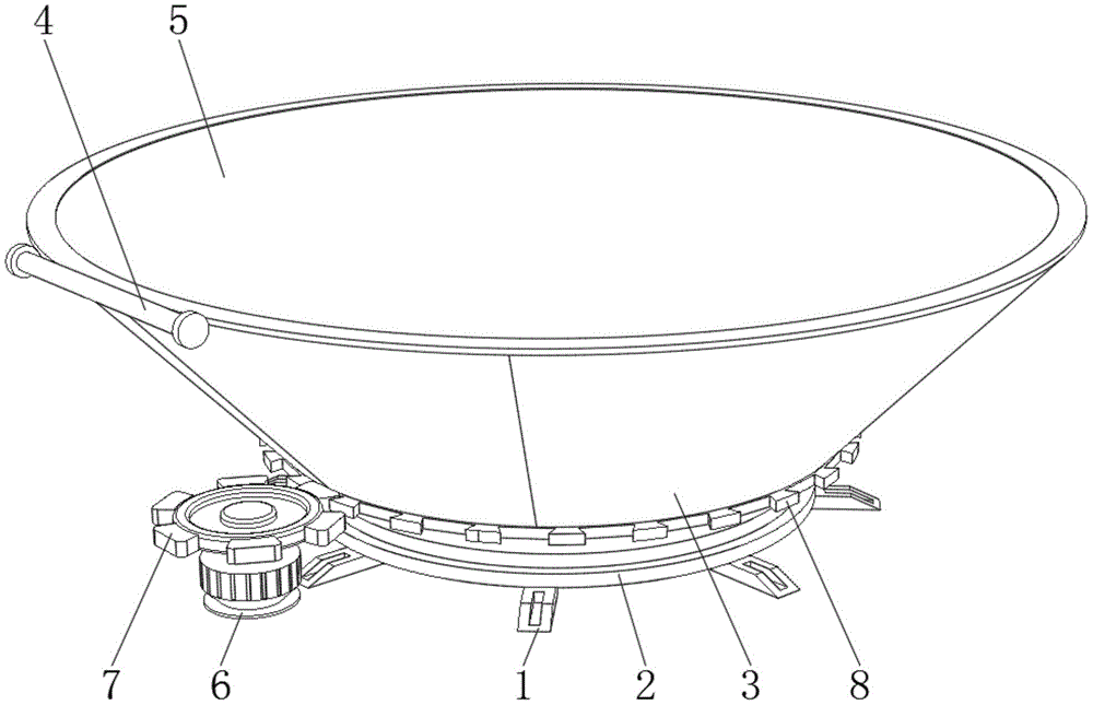
图1为本实用新型提出一种偏光片贴附视觉检测定位装置的立体结构示意图;Fig. 1 is a three-dimensional structural schematic diagram of a polarizer-attached visual detection and positioning device proposed by the utility model;
图2为本实用新型提出一种偏光片贴附视觉检测定位装置的检测箱板的俯视结构示意图;Fig. 2 is a top view structure schematic diagram of a detection box board with a polarizer attached to a visual detection and positioning device proposed by the utility model;
图3为本实用新型提出一种偏光片贴附视觉检测定位装置的底座的结构示意图;Fig. 3 is a structural schematic diagram of a base of a polarizer attached to a visual detection and positioning device proposed by the utility model;
图4为本实用新型提出一种偏光片贴附视觉检测定位装置的定位组件的结构示意图。FIG. 4 is a structural schematic diagram of a positioning component of a polarizer-attached visual detection and positioning device proposed by the present invention.
图例说明:1、防滑垫;2、底座;3、检测箱板;4、转动杆;5、玻璃罩;6、转动电机;7、主动齿轮;8、从动齿环;9、定位组件;10、弹性柱;11、防偏板;12、通电环;13、检验灯;14、控制开关;91、固定杆;92、方形板;93、定位板;94、挡板;95、橡胶板。Legend: 1. Anti-slip mat; 2. Base; 3. Detection box plate; 4. Rotating rod; 5. Glass cover; 6. Rotating motor; 7. Driving gear; 8. Driven gear ring; 9. Positioning component; 10. Elastic column; 11. Anti-bias plate; 12. Power ring; 13. Inspection light; 14. Control switch; 91. Fixed rod; 92. Square plate; 93. Positioning plate; 94. Baffle plate; 95. Rubber plate .
具体实施方式detailed description
为了能够更清楚地理解本实用新型的上述目的、特征和优点,下面结合附图和实施例对本实用新型做进一步说明。需要说明的是,在不冲突的情况下,本申请的实施例及实施例中的特征可以相互组合。In order to understand more clearly the above purpose, features and advantages of the utility model, the utility model will be further described below in conjunction with the accompanying drawings and embodiments. It should be noted that, in the case of no conflict, the embodiments of the present application and the features in the embodiments can be combined with each other.
在下面的描述中阐述了很多具体细节以便于充分理解本实用新型,但是,本实用新型还可以采用不同于在此描述的其他方式来实施,因此,本实用新型并不限于下面公开说明书的具体实施例的限制。In the following description, a lot of specific details have been set forth in order to fully understand the utility model, but the utility model can also be implemented in other ways that are different from those described here. Therefore, the utility model is not limited to the specific details of the following disclosure EXAMPLE LIMITATIONS.
请参阅图1-4,本实用新型提供一种技术方案:一种偏光片贴附视觉检测定位装置,包括底座2、转动电机6、主动齿轮7、检测箱板3、玻璃罩5和防偏板11,底座2的顶部与检测箱板3的底部滑动连接,检测箱板3的底部外侧固定连接有从动齿环8,转动电机6的顶部与主动齿轮7的底部活动安装,主动齿轮7的外侧与从动齿环8的外侧啮合,转动电机6带动顶部主动齿轮7转动,主动齿轮7带动从动齿环8转动,从而带动检测箱板3和定位组件9整体匀速缓慢转动,检测箱板3的底端内侧固定连接有定位组件9,定位组件9包括方形板92和挡板94,挡板94和防偏板11可以避免偏光片向外侧倾倒,使偏光片稳定地放置在定位板93顶部,方形板92的顶部均匀固定连接有四个定位板93,定位板93的顶部一端与挡板94的底部固定安装,定位板93的顶部另一端设置有橡胶板95,偏光片的底部和橡胶板95接触,橡胶板95可以避免偏光片底部磨损。Please refer to Figures 1-4, the utility model provides a technical solution: a visual detection and positioning device attached to a polarizer, including a
方形板92的两端对称固定连接有四个固定杆91,固定杆91的一端与检测箱板3的内侧固定安装,固定杆91用于将方形板92固定在检测箱板3内壁。The two ends of the
检测箱板3的内侧均匀固定连接有四个弹性柱10,弹性柱10的一端与防偏板11的一侧活动连接,防偏板11可以避免偏光片向外侧倾倒,使偏光片稳定地放置在定位板93顶部。The inner side of the
检测箱板3的顶部一端固定连接有转动杆4,转动杆4的外侧与玻璃罩5的一端转动连接,转动杆4方便打开玻璃罩5。One end of the top of the
底座2的底部均匀固定连接有多个防滑垫1,底座2的顶部内侧固定连接有通电环12,防滑垫1起到防滑作用,通过控制开关14可以使通电环12通电,从而使检验灯13发出稳定光源。The bottom of the
通电环12的内侧设置有多个检验灯13,通电环12的一侧设置有控制开关14,通过控制开关14打开检验灯13,检验灯13发出稳定光源。The inner side of the
防偏板11设置在挡板94的顶部,定位板93的内侧活动连接有偏光片,挡板94和防偏板11可以避免偏光片向外侧倾倒。The anti-polarizer 11 is arranged on the top of the
本实施例的工作原理:该装置主要由玻璃罩5、检测箱板3、定位组件9、底座2和转动电机6组成,在需要对偏光片进行检测时,首先翻转打开玻璃罩5,将偏光片对准定位板93的卡槽向下放置,将偏光片平稳地放置在定位板93和橡胶板95之间的卡槽内,偏光片为向外倾斜放置,偏光片的底部和橡胶板95接触,橡胶板95可以避免偏光片底部磨损,同时挡板94和防偏板11可以避免偏光片向外侧倾倒,使偏光片稳定地放置在定位板93顶部;待四个偏光片均放置好后通过控制开关14打开检验灯13,检验灯13发出稳定光源,关闭玻璃罩5,同时开启转动电机6,转动电机6带动顶部主动齿轮7转动,主动齿轮7带动从动齿环8转动,从而带动检测箱板3和定位组件9整体匀速缓慢转动,将传统的静态状态视觉检测转换为动态视觉检测,使检测人员可以仔细辨别偏光片上的所有视觉缺陷,避免人工手持检测时造成的偏光片损坏;同时一个检测箱板3内可以同时放置四块偏光片,可以一次对四块偏光片进行视觉检测,提高偏光片的视觉检测效率。The working principle of this embodiment: the device is mainly composed of a
以上所述,仅是本实用新型的较佳实施例而已,并非对本实用新型作其他形式的限制,任何熟悉本专业的技术人员可能利用上述揭示的技术内容加以变更或改型为等同变化的等效实施例应用于其它领域,但是凡是未脱离本实用新型技术方案内容,依据本实用新型的技术实质对以上实施例所作的任何简单修改、等同变化与改型,仍属于本实用新型技术方案的保护范围。The above is only a preferred embodiment of the utility model, and does not limit the utility model in other forms. Any skilled person who is familiar with this profession may use the technical content disclosed above to change or remodel it into an equivalent change, etc. The effective embodiments are applied to other fields, but any simple modification, equivalent change and modification made to the above embodiments according to the technical essence of the present invention without departing from the content of the technical solution of the present utility model still belong to the technical solution of the present utility model. protected range.
Claims (7)
Priority Applications (1)
| Application Number | Priority Date | Filing Date | Title |
|---|---|---|---|
| CN202221704750.3U CN218036480U (en) | 2022-07-04 | 2022-07-04 | A visual detection and positioning device for attaching a polarizer |
Applications Claiming Priority (1)
| Application Number | Priority Date | Filing Date | Title |
|---|---|---|---|
| CN202221704750.3U CN218036480U (en) | 2022-07-04 | 2022-07-04 | A visual detection and positioning device for attaching a polarizer |
Publications (1)
| Publication Number | Publication Date |
|---|---|
| CN218036480U true CN218036480U (en) | 2022-12-13 |
Family
ID=84379826
Family Applications (1)
| Application Number | Title | Priority Date | Filing Date |
|---|---|---|---|
| CN202221704750.3U Active CN218036480U (en) | 2022-07-04 | 2022-07-04 | A visual detection and positioning device for attaching a polarizer |
Country Status (1)
| Country | Link |
|---|---|
| CN (1) | CN218036480U (en) |
Cited By (1)
| Publication number | Priority date | Publication date | Assignee | Title |
|---|---|---|---|---|
| CN116908145A (en) * | 2023-06-30 | 2023-10-20 | 江苏晶瑞玻璃有限公司 | Fingerprint-proof high-light-transmittance glassware detection device and detection method thereof |
-
2022
- 2022-07-04 CN CN202221704750.3U patent/CN218036480U/en active Active
Cited By (2)
| Publication number | Priority date | Publication date | Assignee | Title |
|---|---|---|---|---|
| CN116908145A (en) * | 2023-06-30 | 2023-10-20 | 江苏晶瑞玻璃有限公司 | Fingerprint-proof high-light-transmittance glassware detection device and detection method thereof |
| CN116908145B (en) * | 2023-06-30 | 2024-03-26 | 江苏晶瑞玻璃有限公司 | Fingerprint-proof high-light-transmittance glassware detection device and detection method thereof |
Similar Documents
| Publication | Publication Date | Title |
|---|---|---|
| CN104536171B (en) | Liquid crystal display screen detection device | |
| CN203337939U (en) | Detection device of liquid crystal display panel | |
| CN106990567A (en) | A kind of macro inspection apparatus and macro inspection method | |
| CN110987374A (en) | Lamp house with shading function | |
| CN206421116U (en) | LCD liquid crystal screen detection device | |
| CN105510346A (en) | Light guide test jig capable of achieving viewing adjustment | |
| CN209821546U (en) | Detection device for liquid crystal display screen | |
| CN203705754U (en) | Liquid crystal display panel detection device | |
| CN211928347U (en) | Liquid crystal display macroscopic defect inspection equipment | |
| CN110727131A (en) | A detection device for liquid crystal display production | |
| CN207439649U (en) | AR optical surface eyeglass detection devices | |
| CN203799148U (en) | Macroscopic detection machine for substrate | |
| CN211603807U (en) | Polaroid filtering and reflecting mechanism | |
| CN205754636U (en) | A kind of novel electric power apparatus failure detector | |
| CN103680369A (en) | Testing device and testing method of displayer module | |
| CN103901644B (en) | A kind of lighting jig and lighting test method | |
| CN219161967U (en) | Quick detection device of support plate glass for display screen | |
| CN108956094A (en) | A kind of semi-transparent LCD polaroid glasses test panel showcase | |
| CN205982123U (en) | Adj. tabular product surface defect polarized light imaging system | |
| CN218239880U (en) | Defect detection equipment for photoelectric optical lens | |
| CN207816302U (en) | A large-enclosed automatic image measuring instrument | |
| CN223408843U (en) | A detection device for display production | |
| CN219085242U (en) | Detection device of general liquid crystal display | |
| CN111290194A (en) | A kind of polarizer filter reflection mechanism | |
| CN221859457U (en) | A surface smoothness detection device for lamp bead production |
Legal Events
| Date | Code | Title | Description |
|---|---|---|---|
| GR01 | Patent grant | ||
| GR01 | Patent grant | ||
| PE01 | Entry into force of the registration of the contract for pledge of patent right | ||
| PE01 | Entry into force of the registration of the contract for pledge of patent right |
Denomination of utility model: A polarizing film attachment visual inspection positioning device Granted publication date: 20221213 Pledgee: China Construction Bank Co.,Ltd. Yancheng Chengnan sub branch Pledgor: Jiangsu zunshen Technology Co.,Ltd. Registration number: Y2026980015517 |