CN218020181U - Ventilation cooling structure for 3D printer - Google Patents
Ventilation cooling structure for 3D printer Download PDFInfo
- Publication number
- CN218020181U CN218020181U CN202222624930.7U CN202222624930U CN218020181U CN 218020181 U CN218020181 U CN 218020181U CN 202222624930 U CN202222624930 U CN 202222624930U CN 218020181 U CN218020181 U CN 218020181U
- Authority
- CN
- China
- Prior art keywords
- printer
- cooling structure
- sides
- heat dissipation
- wall
- Prior art date
- Legal status (The legal status is an assumption and is not a legal conclusion. Google has not performed a legal analysis and makes no representation as to the accuracy of the status listed.)
- Active
Links
Images


Landscapes
- Accessory Devices And Overall Control Thereof (AREA)
Abstract
本实用新型公开了3D打印机技术领域的一种3D打印机用的通风降温结构,包括3D打印机主体,3D打印机主体的两侧壁均开设有散热口,散热口的内侧安装有盒体,盒体的内腔顶部设有导热片,导热片的底部设有多组散热铜管,且散热铜管的底端设有抽风机,3D打印机主体的两侧外壁且位于散热口的外侧设有安装框,安装框内设有防尘网、吸湿过滤网板,安装框的两侧开设有定位槽,3D打印机主体的两侧外壁且位于安装框的两端连接有安装座,且安装座内设有与定位槽相适配的定位块,本实用新型的散热铜管、导热片具有良好的导热作用,配合抽风机的使用,能够将热量快速排出,实现了高效通风降温,有效保护了3D打印机。
The utility model discloses a ventilation and cooling structure for 3D printers in the technical field of 3D printers. The top of the inner cavity is provided with a heat conduction sheet, the bottom of the heat conduction sheet is provided with multiple sets of heat dissipation copper tubes, and the bottom of the heat dissipation copper pipe is provided with an exhaust fan, and the outer walls on both sides of the main body of the 3D printer are provided with installation frames outside the heat dissipation port. There are dust-proof nets and moisture-absorbing filter panels in the installation frame, and positioning grooves are opened on both sides of the installation frame. The outer walls on both sides of the main body of the 3D printer and the two ends of the installation frame are connected with installation seats, and there are installation seats in the installation seat. The positioning block matched with the positioning groove, the heat dissipation copper tube and the heat conduction sheet of the utility model have good heat conduction effect, cooperate with the use of the exhaust fan, can quickly discharge the heat, realize efficient ventilation and cooling, and effectively protect the 3D printer.
Description
技术领域technical field
本实用新型涉及3D打印机技术领域,具体为一种3D打印机用的通风降温结构。The utility model relates to the technical field of 3D printers, in particular to a ventilation and cooling structure for 3D printers.
背景技术Background technique
3D打印机又叫三维打印机,3D打印机在夏季使用时,其内部会产生大量的热,热量多是通过自然冷却的方式降温,降温效果不佳,若不能及时快速将热量排出,会对3D打印机内的零件会造成伤害,甚至会使3D打印机烧坏,为此,我们提出一种3D打印机用的通风降温结构。3D printers are also called three-dimensional printers. When a 3D printer is used in summer, it will generate a lot of heat inside. Most of the heat is cooled by natural cooling. The cooling effect is not good. The parts will cause damage and even burn out the 3D printer. Therefore, we propose a ventilation and cooling structure for 3D printers.
实用新型内容Utility model content
本实用新型的目的在于提供一种3D打印机用的通风降温结构,以解决上述背景技术中提出的问题。The purpose of this utility model is to provide a ventilation and cooling structure for 3D printers, so as to solve the problems raised in the above-mentioned background technology.
为实现上述目的,本实用新型提供如下技术方案:In order to achieve the above object, the utility model provides the following technical solutions:
一种3D打印机用的通风降温结构,包括3D打印机主体,3D打印机主体的两侧壁均开设有散热口,散热口的内侧安装有盒体,盒体的内腔顶部设有导热片,导热片的底部设有多组散热铜管,且散热铜管的底端设有抽风机,3D打印机主体的两侧外壁且位于散热口的外侧设有安装框,安装框内设有防尘网、吸湿过滤网板,安装框的两侧开设有定位槽,3D打印机主体的两侧外壁且位于安装框的两端连接有安装座,且安装座内设有与定位槽相适配的定位块。A ventilation and cooling structure for a 3D printer, comprising a 3D printer main body, the two side walls of the 3D printer main body are provided with cooling vents, a box body is installed on the inner side of the cooling vent, and a heat conducting sheet is arranged on the top of the inner cavity of the box body, and the heat conducting sheet The bottom of the 3D printer is equipped with multiple sets of heat dissipation copper tubes, and the bottom of the heat dissipation copper tubes is equipped with an exhaust fan. The outer walls on both sides of the main body of the 3D printer and the outside of the heat dissipation port are equipped with installation frames. The filter plate is provided with positioning grooves on both sides of the installation frame, and the two outer walls of the main body of the 3D printer are connected with installation seats at both ends of the installation frame, and the installation seats are provided with positioning blocks suitable for the positioning grooves.
进一步的:安装座靠近安装框的一面开设有槽口,且安装座的中部连接有调节杆,调节杆的底端与定位块的内侧面中部连接。Further: a notch is provided on the side of the mounting seat close to the mounting frame, and the middle part of the mounting seat is connected with an adjustment rod, and the bottom end of the adjustment rod is connected with the middle part of the inner surface of the positioning block.
进一步的:调节杆的底端外壁设有滑动板,且滑动板的两侧壁与安装座的内壁滑动连接,滑动板与安装座内壁之间设有弹簧。Further: the outer wall of the bottom end of the adjustment rod is provided with a sliding plate, and the two side walls of the sliding plate are slidably connected with the inner wall of the mounting seat, and a spring is provided between the sliding plate and the inner wall of the mounting seat.
进一步的:防尘网和吸湿过滤网板通过卡接的方式与安装框连接。Further: the dust-proof net and the moisture-absorbing filter board are connected to the installation frame by clipping.
进一步的:盒体通过螺栓与3D打印机主体的两侧内壁连接。Further: the box body is connected with the inner walls on both sides of the 3D printer main body through bolts.
进一步的:相邻安装座之间的间距略大于安装框的宽度。Further: the distance between adjacent mounting seats is slightly larger than the width of the mounting frame.
进一步的:定位块靠近定位槽的一面均设有防滑垫。Further: the side of the positioning block close to the positioning groove is provided with an anti-skid pad.
与现有技术相比,本实用新型的有益效果是:Compared with the prior art, the beneficial effects of the utility model are:
1、本实用新型的导热片具有良好的导热作用,能够将3D打印机内的热量快速导出,并将热量传导给散热铜管,通过抽风机的作用,能够将散热铜管输出的热量通过散热口快速排出,实现了通风降温,降温效率高,有效保护了3D打印机。1. The heat conduction sheet of the utility model has good heat conduction effect, can quickly export the heat in the 3D printer, and conduct the heat to the heat dissipation copper pipe, and through the action of the exhaust fan, the heat output by the heat dissipation copper pipe can pass through the heat dissipation port Rapid discharge realizes ventilation and cooling, high cooling efficiency, and effectively protects the 3D printer.
2、安装框内的防尘网具有防尘作用,吸湿过滤网板具有吸水作用,避免外部空气中的灰尘、水汽进到3D打印机内部,且通过安装座、调节杆、弹簧、定位块与定位槽的配合使用,能够实现对安装框的快速拆装,便于防尘网、吸湿过滤网板的拆装、清理与更换。2. The dust-proof net in the installation frame has a dust-proof effect, and the moisture-absorbing filter plate has a water-absorbing effect to prevent dust and water vapor in the external air from entering the inside of the 3D printer, and through the mounting seat, adjustment rod, spring, positioning block and positioning The cooperative use of the groove can realize the quick disassembly and assembly of the installation frame, and is convenient for the disassembly, assembly, cleaning and replacement of the dust-proof net and the moisture-absorbing filter net board.
附图说明Description of drawings
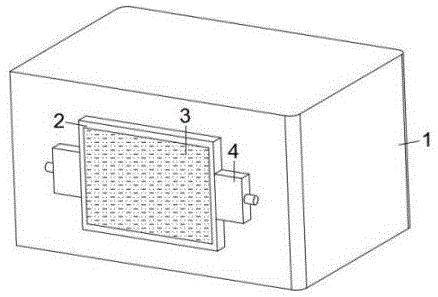
图1为本实用新型结构示意图;Fig. 1 is a structural representation of the utility model;
图2为本实用新型侧面结构剖视图;Fig. 2 is a sectional view of the side structure of the utility model;
图3为本实用新型安装框与安装座连接剖视图;Fig. 3 is a sectional view of the connection between the installation frame and the installation seat of the utility model;
图4为本实用新型安装框结构示意图。Fig. 4 is a structural schematic diagram of the installation frame of the present invention.
图中:1、3D打印机主体;2、安装框;3、防尘网;4、安装座;5、盒体;6、导热片;7、散热铜管;8、抽风机;9、散热口;10、吸湿过滤网板;11、调节杆;12、弹簧;13、滑动板;14、定位槽;15、定位块。In the figure: 1. The main body of the 3D printer; 2. The installation frame; 3. The dust-proof net; 4. The installation base; 5. The box body; ; 10, moisture absorption filter screen plate; 11, adjusting rod; 12, spring; 13, sliding plate; 14, positioning groove; 15, positioning block.
具体实施方式detailed description
下面将结合本实用新型实施例中的附图,对本实用新型实施例中的技术方案进行清楚、完整地描述,显然,所描述的实施例仅仅是本实用新型一部分实施例,而不是全部的实施例。基于本实用新型中的实施例,本领域普通技术人员在没有做出创造性劳动前提下所获得的所有其他实施例,都属于本实用新型保护的范围。The technical solutions in the embodiments of the present invention will be clearly and completely described below in conjunction with the accompanying drawings in the embodiments of the present invention. Obviously, the described embodiments are only part of the embodiments of the present invention, not all of them. example. Based on the embodiments of the present utility model, all other embodiments obtained by persons of ordinary skill in the art without making creative efforts belong to the scope of protection of the present utility model.
实施例1:Example 1:
请参阅图1-4,本实用新型提供一种技术方案:一种3D打印机用的通风降温结构,包括3D打印机主体1,3D打印机主体1的两侧壁均开设有散热口9,散热口9的内侧安装有盒体5,盒体5的内腔顶部设有导热片6,导热片6的底部设有多组散热铜管7,且散热铜管7的底端设有抽风机8,3D打印机主体1的两侧外壁且位于散热口9的外侧设有安装框2,安装框2内设有防尘网3、吸湿过滤网板10,安装框2的两侧开设有定位槽14,3D打印机主体1的两侧外壁且位于安装框2的两端连接有安装座4,且安装座4内设有与定位槽14相适配的定位块15,3D打印机主体1为现有技术,具有的工作原理在此不作说明,其中,抽风机8的电性端电性连接外部电源和控制器的电性端,盒体5的两端均开设有连通设置的通风口;Please refer to Figures 1-4, the utility model provides a technical solution: a ventilation and cooling structure for a 3D printer, including a 3D printer
盒体5内的导热片6与3D打印机主体1内的零件外壁贴合,导热片6具有良好的导热作用,能够将3D打印机主体1内产生的热量输送给散热铜管7,抽风机8再工作,即加快了空气流动速度,能够将散热铜管7输送出来的热量给到散热口9,即实现了通风降温,降温效率更快,避免3D打印机主体1在夏季使用时热量过高而损坏,保护效果好,其中,安装框2内的防尘网3具有防尘作用,避免空气中的灰尘进到3D打印机主体1内,吸湿过滤网板10具有吸水作用,能够将空气中的水汽吸收,避免对3D打印机主体1造成损坏。The
其中,优选的,安装座4靠近安装框2的一面开设有槽口,且安装座4的中部连接有调节杆11,调节杆11的底端与定位块15的内侧面中部连接,调节杆11的底端外壁设有滑动板13,且滑动板13的两侧壁与安装座4的内壁滑动连接,滑动板13与安装座4内壁之间设有弹簧12,在安装框2安装时,两组安装座4内的调节杆11处于外拉状态,定位块15收集在安装座4内,滑动板13上移,弹簧12处于压缩状态,此时的安装框2可顺利安装在相邻安装座4之间,此时安装座4内的槽口正对定位槽14,松开调节杆11,处于压缩的弹簧12回位,即可带动定位块15向内侧移动,定位块15可插接在定位槽14内,从而实现了对安装框2位置的固定,安装框2可便于拆装。Wherein, preferably, the mounting
优选的,防尘网3和吸湿过滤网板10通过卡接的方式与安装框2连接,方便拆装的安装框2拆下后,可便于防尘网3、吸湿过滤网板10的清理、更换。Preferably, the dust-
优选的,盒体5通过螺栓与3D打印机主体1的两侧内壁连接。Preferably, the
优选的,相邻安装座4之间的间距略大于安装框2的宽度。Preferably, the distance between adjacent mounting
实施例2:Example 2:
参照图3,该实施例不同于第一个实施例的是:定位块15靠近定位槽14的一面均设有防滑垫,防滑垫能够起到防滑的作用,增大了定位块15与定位槽14之间的摩擦力,提高了两者连接的稳定性。Referring to Fig. 3, this embodiment is different from the first embodiment in that: the side of the
尽管已经示出和描述了本实用新型的实施例,对于本领域的普通技术人员而言,可以理解在不脱离本实用新型的原理和精神的情况下可以对这些实施例进行多种变化、修改、替换和变型,本实用新型的范围由所附权利要求及其等同物限定。Although the embodiments of the present invention have been shown and described, those skilled in the art can understand that various changes and modifications can be made to these embodiments without departing from the principle and spirit of the present invention , replacements and modifications, the scope of the present utility model is defined by the appended claims and their equivalents.
Claims (7)
Priority Applications (1)
| Application Number | Priority Date | Filing Date | Title |
|---|---|---|---|
| CN202222624930.7U CN218020181U (en) | 2022-10-08 | 2022-10-08 | Ventilation cooling structure for 3D printer |
Applications Claiming Priority (1)
| Application Number | Priority Date | Filing Date | Title |
|---|---|---|---|
| CN202222624930.7U CN218020181U (en) | 2022-10-08 | 2022-10-08 | Ventilation cooling structure for 3D printer |
Publications (1)
| Publication Number | Publication Date |
|---|---|
| CN218020181U true CN218020181U (en) | 2022-12-13 |
Family
ID=84356660
Family Applications (1)
| Application Number | Title | Priority Date | Filing Date |
|---|---|---|---|
| CN202222624930.7U Active CN218020181U (en) | 2022-10-08 | 2022-10-08 | Ventilation cooling structure for 3D printer |
Country Status (1)
| Country | Link |
|---|---|
| CN (1) | CN218020181U (en) |
Cited By (1)
| Publication number | Priority date | Publication date | Assignee | Title |
|---|---|---|---|---|
| CN117021794A (en) * | 2023-09-06 | 2023-11-10 | 深圳市盛天商业机器有限公司 | Printer with multiple functions |
-
2022
- 2022-10-08 CN CN202222624930.7U patent/CN218020181U/en active Active
Cited By (1)
| Publication number | Priority date | Publication date | Assignee | Title |
|---|---|---|---|---|
| CN117021794A (en) * | 2023-09-06 | 2023-11-10 | 深圳市盛天商业机器有限公司 | Printer with multiple functions |
Similar Documents
| Publication | Publication Date | Title |
|---|---|---|
| CN209343254U (en) | A kind of computer cabinet of perfect heat-dissipating | |
| CN205485834U (en) | Heat dissipation is from dust removal computer machine case | |
| CN204833107U (en) | Heat dissipation computer machine case | |
| CN113381326B (en) | A high-efficiency heat dissipation electrical cabinet for electrical engineering | |
| CN101510661B (en) | Laser radiating device and method | |
| CN219131653U (en) | Two-side induced draft smoke exhaust device | |
| CN218564011U (en) | Heat radiation structure of high-temperature-resistant axial flow fan | |
| CN219045928U (en) | An Easy-to-Maintain Total Heat Exchanger | |
| CN219247594U (en) | Heat radiation structure of motor casing | |
| CN219644410U (en) | Server cabinet convenient for heat dissipation | |
| CN219591486U (en) | Standard module fan heat radiation structure | |
| CN211457849U (en) | Intelligent control box that radiating effect is good | |
| CN210348249U (en) | Relay control device | |
| CN216591793U (en) | Environmentally friendly and efficient new air preheater | |
| CN211906214U (en) | A new type of computer network switch cooling device | |
| CN211556595U (en) | Voltage stabilizing transformer with heat dissipation and dust removal functions | |
| CN117133202A (en) | A dust-proof LED display module that is conducive to heat conduction | |
| CN222301247U (en) | Dustproof intelligent power distribution cabinet of high-efficient heat dissipation | |
| CN216209514U (en) | Industrial Internet of things comprehensive tester | |
| CN215068102U (en) | A device for improving heat dissipation performance of CPU | |
| CN218047250U (en) | A regenerative drying machine | |
| CN218977176U (en) | High-efficient heat dissipation power amplifier | |
| CN219421402U (en) | Communication cabinet convenient to heat dissipation | |
| CN220851932U (en) | High-power high-brightness LED flash light source | |
| CN221862295U (en) | Electrical equipment installation cabinet |
Legal Events
| Date | Code | Title | Description |
|---|---|---|---|
| GR01 | Patent grant | ||
| GR01 | Patent grant | ||
| CP03 | Change of name, title or address | ||
| CP03 | Change of name, title or address |
Address after: 221000 Jiangsu Province,Xuzhou City, Economic and Technological Development Zone,Yangshan Road No.101 Patentee after: Jiangsu Vilory Advanced Materials Co.,Ltd. Country or region after: China Address before: Jin Gong Road No. 2, Xuzhou Economic and Technological Development Zone, Xuzhou City, Jiangsu Province Patentee before: JIANGSU VILORY ADVANCED MATERIALS TECHNOLOGY Co.,Ltd. Country or region before: China |