CN218014114U - Repairing mass production screening waste collection device - Google Patents
Repairing mass production screening waste collection device Download PDFInfo
- Publication number
- CN218014114U CN218014114U CN202222017151.0U CN202222017151U CN218014114U CN 218014114 U CN218014114 U CN 218014114U CN 202222017151 U CN202222017151 U CN 202222017151U CN 218014114 U CN218014114 U CN 218014114U
- Authority
- CN
- China
- Prior art keywords
- screening
- fixed
- board
- waste
- screening board
- Prior art date
- Legal status (The legal status is an assumption and is not a legal conclusion. Google has not performed a legal analysis and makes no representation as to the accuracy of the status listed.)
- Active
Links
- 238000012216 screening Methods 0.000 title claims abstract description 120
- 239000002699 waste material Substances 0.000 title claims abstract description 55
- 238000004519 manufacturing process Methods 0.000 title claims abstract description 18
- 230000007246 mechanism Effects 0.000 claims abstract description 23
- 239000000463 material Substances 0.000 claims description 17
- 238000004140 cleaning Methods 0.000 claims description 12
- 238000007599 discharging Methods 0.000 claims 1
- 239000012535 impurity Substances 0.000 abstract description 16
- 238000000034 method Methods 0.000 abstract description 9
- 238000011084 recovery Methods 0.000 abstract description 2
- 238000005096 rolling process Methods 0.000 abstract description 2
- XEEYBQQBJWHFJM-UHFFFAOYSA-N Iron Chemical compound [Fe] XEEYBQQBJWHFJM-UHFFFAOYSA-N 0.000 description 6
- 229910000831 Steel Inorganic materials 0.000 description 6
- 239000010959 steel Substances 0.000 description 6
- 238000007873 sieving Methods 0.000 description 5
- 229910000805 Pig iron Inorganic materials 0.000 description 3
- 239000012141 concentrate Substances 0.000 description 3
- 229910052742 iron Inorganic materials 0.000 description 3
- 230000002045 lasting effect Effects 0.000 description 3
- 230000008569 process Effects 0.000 description 3
- 238000012545 processing Methods 0.000 description 3
- 230000008439 repair process Effects 0.000 description 2
- 239000002893 slag Substances 0.000 description 2
- 238000003723 Smelting Methods 0.000 description 1
- 230000004075 alteration Effects 0.000 description 1
- 230000009286 beneficial effect Effects 0.000 description 1
- 239000011449 brick Substances 0.000 description 1
- 230000010405 clearance mechanism Effects 0.000 description 1
- 238000013461 design Methods 0.000 description 1
- 230000000694 effects Effects 0.000 description 1
- 238000005516 engineering process Methods 0.000 description 1
- 230000006872 improvement Effects 0.000 description 1
- 238000012986 modification Methods 0.000 description 1
- 230000004048 modification Effects 0.000 description 1
- 239000007921 spray Substances 0.000 description 1
- 239000007858 starting material Substances 0.000 description 1
- 235000013547 stew Nutrition 0.000 description 1
- 238000006467 substitution reaction Methods 0.000 description 1
- 230000001502 supplementing effect Effects 0.000 description 1
- 230000001360 synchronised effect Effects 0.000 description 1
Images



Classifications
-
- Y—GENERAL TAGGING OF NEW TECHNOLOGICAL DEVELOPMENTS; GENERAL TAGGING OF CROSS-SECTIONAL TECHNOLOGIES SPANNING OVER SEVERAL SECTIONS OF THE IPC; TECHNICAL SUBJECTS COVERED BY FORMER USPC CROSS-REFERENCE ART COLLECTIONS [XRACs] AND DIGESTS
- Y02—TECHNOLOGIES OR APPLICATIONS FOR MITIGATION OR ADAPTATION AGAINST CLIMATE CHANGE
- Y02P—CLIMATE CHANGE MITIGATION TECHNOLOGIES IN THE PRODUCTION OR PROCESSING OF GOODS
- Y02P10/00—Technologies related to metal processing
- Y02P10/20—Recycling
Landscapes
- Combined Means For Separation Of Solids (AREA)
Abstract
The utility model discloses a repairing mass production screening waste collection device, which belongs to the technical field of waste recovery, and aims at the problems that when the existing waste collection device is used, waste is easy to accumulate on a standing sieve plate, the efficiency of screening impurities is influenced, and the sieve plate needs to be manually cleaned regularly, and the waste time and labor are wasted; the utility model discloses well waste material is rolling in-process waste material in impurity through the automatic bottom that falls into the screening case of sieve mesh on the screening board, with the impurity screening, vibrations mechanism makes the screening board produce the vibrations that last to effectively improve the efficiency that the waste material rolled and sieved on the screening board, clear up fast through the sieve mesh of dredging mechanism on to the screening board, thereby ensure that the screening board keeps higher work efficiency.
Description
Technical Field
The utility model belongs to the technical field of waste recovery, concretely relates to repairing mass production screening garbage collection device.
Background
The pig iron slag supplementing process is characterized by that after the steel is tapped from converter, the pig iron blocks are directly added into the converter by means of waste steel hopper, and then the iron blocks are attached to the large surface of the converter body by means of movement of the converter body and utilizing viscosity of slag and cold effect of iron blocks, then the slag-splashing furnace-protecting operation is implemented, so that the slag-splashing layer is formed on the surface of the iron blocks so as to attain the goal of protecting furnace. The method is simple to operate, low in labor intensity, and capable of greatly reducing the auxiliary time compared with the traditional brick repair and spray repair process, and is gradually adopted by various large steel plants.
In the actual production process, a material such as pig iron for fettling is added by the steel scrap hopper, and this kind of steel scrap hopper bottom plate face is mostly U type face to the steel scrap gets into converter stove bottom fast, and the smelting furnace can produce the waste material in the use, need use garbage collection device when collecting the waste residue, and current garbage collection device has following not enough when using:
(1) the waste material is collected to current garbage collection device adopts a collecting box or collection fill to collect the waste material usually, sets up the sieve that just is the slope and arranges wherein and screens out the impurity in the waste material, and the structure is too simple, and the waste material is piled up easily on the sieve of stewing, influences the efficiency of screening out impurity.
(2) The sieve on the current garbage collection device is after long-time continuous operation, and the sieve mesh on the sieve takes place to block up easily, leads to sieve work efficiency to descend, needs the manual work regularly to clear up, wastes time and energy.
Therefore, need a mending material production screening garbage collection device, when solving current garbage collection device and using, the waste material is piled up on the sieve that stews easily, influences the efficiency and the sieve of screening impurity and need artifical the regularly clearance, the problem that wastes time and energy.
Disclosure of Invention
An object of the utility model is to provide a mending material production screening garbage collection device to solve the problem that proposes in the above-mentioned background art.
In order to achieve the above purpose, the utility model provides a following technical scheme: the utility model provides a mending material production screening garbage collection device, includes the screening case, top one side of screening case is provided with the waste material discharge pipe, the inside wall of screening case is fixed with the screening board that is the slope and arranges, the discharge gate that is located the lower end department of screening board is seted up to the one end of screening case, place the collection box under the discharge gate, screening bottom of the case portion is provided with the vibrations mechanism that is located screening board below, one side of screening board is provided with the mechanism of clearing away, the clearance mouth has been seted up on the bottom side of screening case, it has the apron to articulate in the clearance mouth.
It needs to explain in the scheme that, vibration mechanism includes two fixed rotation seats with the bottom inside wall of screening case, one of them rotate and be fixed with the motor on the seat, the output of motor is fixed with cam a, another it is connected with the axis of rotation to rotate the seat top rotation, all be fixed with the belt pulley in the output of motor and the axis of rotation, two common tensioning has the belt on the belt pulley, the axis of rotation is kept away from the end fixing who rotates the seat and is had cam b.
It is further worth explaining that the clearing mechanism comprises a connecting rod connected with the side wall of the screening box in a sliding mode, a cleaning plate located above the top end of the screening plate is fixed to the inner side end of the connecting rod, a cleaning brush in side face contact with the top end of the screening plate is fixed to the bottom end of the cleaning plate, and a push rod is fixed to the outer side end of the connecting rod.
It should be further noted that a material guide plate fixed to the outer side wall of the screening box is arranged at the bottom end of the discharge port, and the material guide plate is obliquely arranged.
In a preferred embodiment, a baffle is fixed at the top of one end of the screening box close to the waste discharge pipe, and the top end of the baffle is in contact with the bottom end of the waste discharge pipe.
In a preferred embodiment, a rubber sleeve is sleeved on the surface of the push rod, and the length of the rubber sleeve is equal to that of the push rod.
Compared with the prior art, the utility model provides a pair of repairing mass production screening garbage collection device includes following beneficial effect at least:
(1) The waste material of repairing material production passes through the waste material discharge pipe and discharges on the screening board, and the waste material rolls automatically on being the screening board that the slope was arranged, and the waste material rolls in-process waste material impurity and falls into the bottom of screening case automatically through the sieve mesh on the screening board, screens impurity, and the waste material falls into in the collection box through the discharge gate, concentrates the collection, makes things convenient for subsequent processing
(2) Drive the axis of rotation through the belt pulley and rotate, the axis of rotation drives cam b and rotates in step to make cam a and cam b carry out lasting the striking to the bottom of screening board, make the screening board produce the vibrations that last, thereby effectively improve the efficiency that the waste material rolled and sieved on the screening board.
(3) Through reciprocal push-and-pull push rod, the connecting rod drives the top reciprocating motion of clearance board at the screening board to make the clearance brush clear up fast the sieve mesh on the screening board, clear through the sieve mesh, thereby ensure that the screening board keeps higher work efficiency.
Drawings
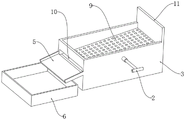
Fig. 1 is a schematic view of the overall structure of the present invention;
fig. 2 is a schematic view of a partial structure of the material guide plate of the present invention;
FIG. 3 is a schematic view of a partial structure of the vibration mechanism of the present invention;
fig. 4 is a schematic structural view of the clearing mechanism of the present invention.
In the figure: 1. a vibration mechanism; 101. a cam a; 102. a cam b; 103. a belt; 104. a rotating seat; 105. a pulley; 106. a rotating shaft; 2. a clearing mechanism; 201. cleaning the plate; 202. cleaning the brush; 203. a connecting rod; 204. a push rod; 3. screening boxes; 4. a waste discharge pipe; 5. a material guide plate; 6. a collection box; 7. a cover plate; 8. cleaning the opening; 9. a screening plate; 10. a discharge port; 11. a baffle plate; 12. a motor; 13. a rubber sleeve.
Detailed Description
The present invention will be further described with reference to the following examples.
In order to make the purpose, technical solution and advantages of the embodiments of the present invention clearer, the following will combine the drawings of the embodiments of the present invention to clearly and completely describe the technical solution of the embodiments of the present invention, and obviously, the described embodiments are a part of the embodiments of the present invention, rather than all embodiments, and all other embodiments obtained by a person of ordinary skill in the art without creative labor are within the scope of the protection of the present invention based on the described embodiments of the present invention.
The following examples are intended to illustrate the invention, but are not intended to limit the scope of the invention. The condition in the embodiment can be further adjusted according to concrete condition the utility model discloses a it is right under the design prerequisite the utility model discloses a simple improvement of method all belongs to the utility model discloses the scope of claiming.
Referring to fig. 1-4, the utility model provides a repairing mass production screening waste collection device, including screening case 3, top one side of screening case 3 is provided with waste discharge pipe 4, the inside wall of screening case 3 is fixed with the screening board 9 that is the slope and arranges, one end of screening case 3 is seted up and is located the discharge gate 10 of screening board 9 lower end department, place collection box 6 under discharge gate 10, the bottom of screening case 3 is provided with vibration mechanism 1 that is located below screening board 9, one side of screening board 9 is provided with clearance mechanism 2, seted up clearance mouth 8 on the bottom side of screening case 3, it has apron 7 to articulate in clearance mouth 8; when in use, the waste material of mending material production is discharged onto screening plate 9 through waste material discharge pipe 4, the waste material is rolled down automatically on screening plate 9 that is the slope and arranges, the waste material rolls down in-process waste material in the roll down bottom that impurity falls into screening case 3 through the sieve mesh is automatic on screening plate 9, screen out impurity, the waste material falls into in collecting box 6 through discharge gate 10, concentrate the collection, make things convenient for subsequent processing, the impurity that falls into screening case 3 bottom clears up impurity from clearance mouth 8 through opening apron 7, simultaneously vibrations mechanism 1 carries out lasting striking to screening plate 9's bottom, make screening plate 9 produce the vibrations that last, thereby effectively improve the efficiency that the waste material rolls down and sieves on screening plate 9, work when screening plate 9 is long-time, when the sieve mesh on screening plate 9 is blockked up, clear up through clearing mechanism 2 and clear up fast the sieve mesh on screening plate 9, clear the sieve mesh through, thereby ensure that screening plate 9 keeps higher work efficiency.
As further shown in fig. 3, it should be specifically noted that the vibrating mechanism 1 includes two rotating bases 104 fixed to the inner side wall of the bottom end of the sieving box 3, one of the rotating bases 104 is fixed with a motor 12, the output end of the motor 12 is fixed with a cam a101, the top end of the other rotating base 104 is rotatably connected with a rotating shaft 106, both the output end of the motor 12 and the rotating shaft 106 are fixed with belt pulleys 105, two belt pulleys 105 are jointly tensioned with a belt 103, and the end of the rotating shaft 106 far away from the rotating base 104 is fixed with a cam b102; the starter motor 12 works, the output end of the motor 12 drives the cam a101 and the belt pulley 105 to rotate, the belt pulley 105 drives the rotating shaft 106 to rotate through the belt 103, the rotating shaft 106 drives the cam b102 to synchronously rotate, so that the cam a101 and the cam b102 continuously knock the bottom of the screening plate 9, the screening plate 9 generates continuous vibration, and the efficiency of rolling and screening waste materials on the screening plate 9 is effectively improved.
As further shown in fig. 1, 2 and 4, it is worth specifically describing that the clearing mechanism 2 includes a connecting rod 203 slidably connected to the side wall of the sieving box 3, a cleaning plate 201 fixed to the inner end of the connecting rod 203 and located above the top end of the sieving plate 9, a cleaning brush 202 fixed to the bottom end of the cleaning plate 201 and contacting the side surface of the top end of the sieving plate 9, and a push rod 204 fixed to the outer end of the connecting rod 203; when screening board 9 works for a long time, when the sieve mesh on screening board 9 is blockked up, through reciprocal push-and-pull push rod 204, connecting rod 203 drives clearance board 201 at the top reciprocating motion of screening board 9 to make clearance brush 202 clear up the sieve mesh on screening board 9 fast, clear up the sieve mesh, thereby ensure that screening board 9 keeps higher work efficiency.
The scheme has the following working processes: waste material that the mending material produced is discharged on screening board 9 through waste material discharge pipe 4, the waste material rolls on the screening board 9 that is the slope and arranges automatically, the waste material rolls the in-process waste material that falls down impurity through the automatic bottom that falls into screening case 3 of sieve mesh on screening board 9, screen impurity, the waste material falls into in collecting box 6 through discharge gate 10, concentrate the collection, make things convenient for subsequent processing, the impurity that falls into screening case 3 bottom clears up impurity from clearance mouth 8 through opening apron 7, start motor 12 works, the output of motor 12 drives cam a101 and belt pulley 105 and rotates, belt pulley 105 drives axis of rotation 106 through belt 103 and rotates, axis of rotation 106 drives cam b102 synchronous rotation, thereby make cam a101 and cam b102 carry out lasting striking to the bottom of screening board 9, make screening board 9 produce the vibrations that last, when screening board 9 works for a long time, when being blocked up on the sieve mesh on screening board 9, through reciprocal push-and pull 204, connecting rod 203 drives clearance board 201 at the top of screening board 9, thereby make clearance sieve mesh clearance carry out reciprocal clearance brush 202 on the quick clearance sieve mesh clearing up.
According to the working process, the following steps are known: vibrations that vibrating mechanism 1 made screening board 9 produce continuously to effectively improve the efficiency that screening board 9 went up the waste material and roll and fall and sieve, clear through mechanism 2 and clear the sieve mesh on screening board 9 and clear through, thereby ensure that screening board 9 keeps higher work efficiency.
As further shown in fig. 1, it is worth specifically describing that a material guide plate 5 fixed to the outer side wall of the screening box 3 is disposed at the bottom end of the discharge port 10, and the material guide plate 5 is arranged in an inclined manner; during specific work, the screened waste materials fall into the collecting box 6 through the material guide plate 5.
As further shown in fig. 1, it should be noted that a baffle plate 11 is fixed on the top of one end of the sieving box 3 near the waste discharge pipe 4, and the top end of the baffle plate 11 contacts with the bottom end of the waste discharge pipe 4.
As further shown in fig. 4, it is worth specifically describing that the rubber sleeve 13 is sleeved on the surface of the push rod 204, and the length of the rubber sleeve 13 is equal to the length of the push rod 204; when the novel push rod 204 works specifically, the arranged rubber sleeve 13 effectively improves the friction force when the push rod 204 is held, and slipping is prevented.
To sum up: vibrations that vibrations mechanism 1 made screening board 9 produce continuously to effectively improve the efficiency that screening board 9 went up the waste material and roll and fall and screen, clear through mechanism 2 and clear the sieve mesh on screening board 9 and clear, thereby ensure that screening board 9 keeps higher work efficiency, waste material after the screening passes through stock guide 5 and falls into collection box 6 in, the frictional force when the rubber sleeve 13 of setting effectively improves and grips push rod 204, prevent the slippage.
The motor 12 is commercially available, and the motor 12 is provided with a power supply, which belongs to the mature technology in the field and is fully disclosed, so that repeated description is omitted in the specification.
Unless otherwise defined, technical or scientific terms used herein shall have the ordinary meaning as understood by those of ordinary skill in the art, and the use of the term "including" or "comprising" in the present application shall mean that the element or item preceding the term covers the element or item listed after the term and its equivalents, but does not exclude other elements or items, and the term "connected" or "connected" is not limited to physical or mechanical connections, and may include electrical connections, whether direct or indirect, "upper", "lower", "left", "right", etc. merely indicate relative positional relationships, and when the absolute position of the object being described is changed, the relative positional relationships may be changed accordingly.
Although embodiments of the present invention have been shown and described, it will be appreciated by those skilled in the art that changes, modifications, substitutions and alterations can be made in these embodiments without departing from the principles and spirit of the invention, the scope of which is defined in the appended claims and their equivalents.
Claims (6)
1. The utility model provides a mending material production screening garbage collection device, includes screening case (3), its characterized in that, top one side of screening case (3) is provided with waste material discharge pipe (4), the inside wall of screening case (3) is fixed with screening board (9) that are the slope and arrange, discharge gate (10) that are located screening board (9) lower extreme department are seted up to the one end of screening case (3), place collection box (6) under discharge gate (10), screening case (3) bottom is provided with vibrating mechanism (1) that are located screening board (9) below, one side of screening board (9) is provided with clear logical mechanism (2), clear mouth (8) have been seted up on the bottom side of screening case (3), it has apron (7) to articulate in clear mouth (8).
2. The scrap collecting device for repairing mass production screening of claim 1, wherein the vibrating mechanism (1) comprises two rotating seats (104) fixed to the inner side wall of the bottom end of the screening box (3), one of the rotating seats (104) is fixed with a motor (12), the output end of the motor (12) is fixed with a cam a (101), the top end of the other rotating seat (104) is rotatably connected with a rotating shaft (106), belt pulleys (105) are fixed to the output end of the motor (12) and the rotating shaft (106), a belt (103) is tensioned on the two belt pulleys (105), and a cam b (102) is fixed to the end portion, far away from the rotating seat (104), of the rotating shaft (106).
3. The scrap collecting device for repairing mass production screening according to claim 2, wherein the clearing mechanism (2) comprises a connecting rod (203) slidably connected with the side wall of the screening box (3), a cleaning plate (201) located above the top end of the screening plate (9) is fixed at the inner side end of the connecting rod (203), a cleaning brush (202) in contact with the side surface of the top end of the screening plate (9) is fixed at the bottom end of the cleaning plate (201), and a push rod (204) is fixed at the outer side end of the connecting rod (203).
4. The scrap collecting device for repairing mass production screening according to claim 1, wherein a material guiding plate (5) fixed to the outer side wall of the screening box (3) is provided at the bottom end of the discharging port (10), and the material guiding plate (5) is arranged in an inclined manner.
5. The scrap collecting apparatus for foundry goods production screening according to claim 4, wherein a baffle (11) is fixed to the top of one end of the screening box (3) close to the scrap discharge pipe (4), and the top end of the baffle (11) contacts with the bottom end of the scrap discharge pipe (4).
6. The scrap collecting device for repairing mass production screening of claim 3, wherein the surface of the push rod (204) is sleeved with a rubber sleeve (13), and the length of the rubber sleeve (13) is equal to the length of the push rod (204).
Priority Applications (1)
| Application Number | Priority Date | Filing Date | Title |
|---|---|---|---|
| CN202222017151.0U CN218014114U (en) | 2022-08-02 | 2022-08-02 | Repairing mass production screening waste collection device |
Applications Claiming Priority (1)
| Application Number | Priority Date | Filing Date | Title |
|---|---|---|---|
| CN202222017151.0U CN218014114U (en) | 2022-08-02 | 2022-08-02 | Repairing mass production screening waste collection device |
Publications (1)
| Publication Number | Publication Date |
|---|---|
| CN218014114U true CN218014114U (en) | 2022-12-13 |
Family
ID=84344129
Family Applications (1)
| Application Number | Title | Priority Date | Filing Date |
|---|---|---|---|
| CN202222017151.0U Active CN218014114U (en) | 2022-08-02 | 2022-08-02 | Repairing mass production screening waste collection device |
Country Status (1)
| Country | Link |
|---|---|
| CN (1) | CN218014114U (en) |
Cited By (3)
| Publication number | Priority date | Publication date | Assignee | Title |
|---|---|---|---|---|
| CN116001092A (en) * | 2023-02-10 | 2023-04-25 | 江苏晨日环保科技有限公司 | Low-emission dry powder mortar manufacturing equipment and application method thereof |
| CN116587155A (en) * | 2023-07-06 | 2023-08-15 | 上海普偌迈机电制造有限公司 | A deburring and grinding device for integral bumper parts |
| CN117920568A (en) * | 2024-01-23 | 2024-04-26 | 贵州四季常青药业有限公司 | A sugar paste cooling device based on throat lozenge production |
-
2022
- 2022-08-02 CN CN202222017151.0U patent/CN218014114U/en active Active
Cited By (3)
| Publication number | Priority date | Publication date | Assignee | Title |
|---|---|---|---|---|
| CN116001092A (en) * | 2023-02-10 | 2023-04-25 | 江苏晨日环保科技有限公司 | Low-emission dry powder mortar manufacturing equipment and application method thereof |
| CN116587155A (en) * | 2023-07-06 | 2023-08-15 | 上海普偌迈机电制造有限公司 | A deburring and grinding device for integral bumper parts |
| CN117920568A (en) * | 2024-01-23 | 2024-04-26 | 贵州四季常青药业有限公司 | A sugar paste cooling device based on throat lozenge production |
Similar Documents
| Publication | Publication Date | Title |
|---|---|---|
| CN112126751A (en) | Quenching water tank structure for steel ball smelting industrial processing | |
| CN211678229U (en) | Deironing device is carried to glass sediment | |
| CN210907367U (en) | Sorting and impurity removing device for scrap iron for steelmaking | |
| CN110181326A (en) | A kind of bushel iron bits cleaning equipment | |
| CN210230575U (en) | Sand-stone separating device for construction waste | |
| CN210411457U (en) | Rotary screening device for metallurgical equipment | |
| CN111760681A (en) | Construction waste screening device | |
| CN108439142B (en) | Automatic transportation equipment for construction waste | |
| CN213134450U (en) | Environment-friendly construction waste treatment device | |
| CN211677981U (en) | Movable construction waste treatment equipment | |
| CN218443403U (en) | Electric smelting brick electric arc furnace dust removal mechanism | |
| CN110404764A (en) | A kind of smelt uses clinker high-efficient treatment device | |
| CN119468703A (en) | Electric furnace for steel rolling | |
| CN214269024U (en) | Material conveying device for scrap iron removal of waste plastics | |
| CN112845081B (en) | Multistage centrifugal screening equipment of gravel and sand edulcoration | |
| CN209829566U (en) | Drum screen cleaner | |
| CN114471807A (en) | Broken recovery unit of rubbish is built in room | |
| CN213611976U (en) | Metal and nonmetal sieving mechanism for garbage classification | |
| KR100782739B1 (en) | Automatic powder removing device on roll surface | |
| CN212856177U (en) | Sieving mechanism for construction waste treatment | |
| CN222670697U (en) | A high-efficient pushing off slag device for rotary hearth furnace | |
| CN112473851A (en) | Building rubbish breaker for building engineering | |
| CN222446655U (en) | Construction waste crushing device | |
| CN217147524U (en) | Special full-automatic clearance mechanism of vortex sorter belt | |
| CN223531071U (en) | Neodymium iron boron casting sheet post-crushing device |
Legal Events
| Date | Code | Title | Description |
|---|---|---|---|
| GR01 | Patent grant | ||
| GR01 | Patent grant |