CN217992542U - Battery tray production is got device with end plate not damaged clamp - Google Patents
Battery tray production is got device with end plate not damaged clamp Download PDFInfo
- Publication number
- CN217992542U CN217992542U CN202221925414.1U CN202221925414U CN217992542U CN 217992542 U CN217992542 U CN 217992542U CN 202221925414 U CN202221925414 U CN 202221925414U CN 217992542 U CN217992542 U CN 217992542U
- Authority
- CN
- China
- Prior art keywords
- plate
- fixedly connected
- push rod
- rigid coupling
- battery tray
- Prior art date
- Legal status (The legal status is an assumption and is not a legal conclusion. Google has not performed a legal analysis and makes no representation as to the accuracy of the status listed.)
- Active
Links
Images

Landscapes
- Battery Mounting, Suspending (AREA)
Abstract
The utility model discloses a new energy automobile technical field's a device is got with end plate not damaged clamp to battery tray production, including the hanger plate, the bottom rigid coupling of hanger plate has two-way electric push rod, the hoist and mount spout of two sets of symmetries is seted up to the bottom of hanger plate, sliding connection has the hoist and mount slider on the hoist and mount spout, the bottom rigid coupling of hoist and mount slider has the curb plate, two sets of curb plates respectively the rigid coupling at the both ends of electric push rod, the equal rigid coupling in one side that two sets of curb plates kept away from each other has the motor, the power take off end rigid coupling of motor has the gear, the opening has been seted up on the curb plate, the opposite side rigid coupling of curb plate has fixed plate and loading board, it has the gag lever post to run through on the fixed plate to peg graft, the bottom rigid coupling of gag lever post has the clamp plate. The utility model has simple structure and convenient operation, and is provided with the anti-skid buffer cushion by matching the motor with the electric push rod, thereby improving the clamping safety and avoiding the damage of the tray; through setting up curved push rod, be convenient for press from both sides the tray of unidimensional not and get, improve the flexibility, be convenient for widely use.
Description
Technical Field
The utility model relates to a new energy automobile technical field specifically is a device is got with end plate not damaged clamp to battery tray production.
Background
A battery refers to a device that converts chemical energy into electrical energy in a portion of the space of a cup, tank, or other container or composite container that holds an electrolyte solution and metal electrodes to produce an electrical current. Has a positive electrode and a negative electrode. With the advancement of technology, batteries generally refer to small devices capable of generating electrical energy. Such as a solar cell. The performance parameters of the battery are mainly electromotive force, capacity, specific energy and resistance. The battery is used as an energy source, can obtain current which has stable voltage and current, is stably supplied for a long time and is slightly influenced by the outside, has simple structure, convenient carrying, simple and easy charging and discharging operation, is not influenced by the outside climate and temperature, has stable and reliable performance, and plays a great role in various aspects of modern social life. The battery can be applied to new energy automobiles.
Need press from both sides when battery tray production is processed and get, the equipment hardness of getting is too high for most clamp at present, causes the tray damage easily, and is not convenient for nimble use.
Based on this, the utility model designs a device is got with end plate not damaged clamp to battery tray production to solve above-mentioned problem.
SUMMERY OF THE UTILITY MODEL
An object of the utility model is to provide a device is got with end plate not damaged clamp to battery tray production is got to need press from both sides when battery tray production adds that proposes in solving above-mentioned background art and gets, and the equipment hardness is too high to press from both sides at present most, causes the tray damage easily, and is not convenient for the problem of nimble use.
In order to achieve the above object, the utility model provides a following technical scheme: the utility model provides a device is got with end plate not damaged clamp to battery tray production, includes the hanger plate, the bottom rigid coupling of hanger plate has two-way electric push rod, the hoist and mount spout of two sets of symmetries is seted up to the bottom of hanger plate, sliding connection has the hoist and mount slider on the hoist and mount spout, the bottom rigid coupling of hoist and mount slider has the curb plate, and is two sets of curb plate difference rigid coupling is in the both ends of electric push rod, and is two sets of the equal rigid coupling in one side that the curb plate was kept away from each other has the motor, the power take off end rigid coupling of motor has the gear, the opening has been seted up on the curb plate, the opposite side rigid coupling of curb plate has fixed plate and loading board, it has the gag lever post to run through on the fixed plate, the bottom rigid coupling of gag lever post has the clamp plate, the briquetting spout has been seted up at the top of clamp plate, sliding connection has the briquetting in the briquetting spout, the bottom rigid coupling of fixed plate has the rotating lever plate, rotating rod is connected with the bull stick through the bearing rotation on the rotating rod, the rigid coupling has the arm on the bull rod, prop up the arm has the push rod, the one end of push rod with the top of briquetting is articulated, the lateral wall of push rod, the rack with gear meshes mutually.
Preferably, the hanger plate is provided with a mounting hole, so that the device can be conveniently mounted.
Preferably, the gear and the rack are positioned in the opening, so that transmission is facilitated.
Preferably, the top of loading board with the equal rigid coupling in bottom of clamp plate has anti-skidding blotter, improves to press from both sides and gets stability.
Preferably, the push rod is arc-shaped, so that the press plate is driven to press down conveniently.
Compared with the prior art, the beneficial effects of the utility model are that:
1. the utility model has simple structure and convenient operation, and is provided with the anti-skid buffer cushion by matching the motor with the electric push rod, thereby improving the clamping safety and avoiding the damage of the tray;
2. through setting up curved push rod, be convenient for press from both sides the tray of unidimensional and get, improve the flexibility, be convenient for widely use.
Of course, it is not necessary for any particular product to achieve all of the above-described advantages simultaneously.
Drawings
In order to more clearly illustrate the technical solutions of the embodiments of the present invention, the drawings used in the description of the embodiments are briefly introduced below, it is obvious that the drawings in the description below are only some embodiments of the present invention, and for those skilled in the art, other drawings can be obtained according to the drawings without creative efforts.
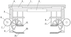
FIG. 1 is a schematic view of the present invention;
fig. 2 is a partial enlarged view of the present invention.
In the drawings, the reference numbers indicate the following list of parts:
1-hanging plate, 2-bidirectional electric push rod, 3-hanging chute, 4-hanging slide block, 5-side plate, 6-motor, 7-gear, 8-opening, 9-fixing plate, 10-bearing plate, 11-limiting rod, 12-pressing plate, 13-pressing block chute, 14-pressing block, 15-rotating rod plate, 16-rotating rod, 17-supporting arm, 18-push rod, 19-rack and 20-anti-skid buffer pad.
Detailed Description
The technical solutions in the embodiments of the present invention will be described clearly and completely with reference to the accompanying drawings in the embodiments of the present invention, and it is obvious that the described embodiments are only some embodiments of the present invention, not all embodiments. Based on the embodiments of the present invention, all other embodiments obtained by a person skilled in the art without making creative efforts belong to the protection scope of the present invention.
Referring to fig. 1-2, the present invention provides a technical solution: the utility model provides a device is got with end plate not damaged clamp to battery tray production, including hanger plate 1, the bottom rigid coupling of hanger plate 1 has two-way electric putter 2, hoist and mount spout 3 of two sets of symmetries is seted up to hanger plate 1's bottom, sliding connection has hoist and mount slider 4 on hoist and mount spout 3, the bottom rigid coupling of hoist and mount slider 4 has curb plate 5, two sets of curb plate 5 respectively the both ends of rigid coupling at electric putter 2, the equal rigid coupling in one side that two sets of curb plate 5 kept away from each other has motor 6, motor 6's power take off end rigid coupling has gear 7, opening 8 has been seted up on curb plate 5, the opposite side rigid coupling of curb plate 5 has fixed plate 9 and loading board 10, it has gag lever post 11 to run through the grafting on the fixed plate 9, the bottom rigid coupling of gag lever post 11 has clamp plate 12, briquetting spout 13 has been seted up at the top of clamp plate 12, sliding connection has briquetting 14 in briquetting spout 13, the bottom rigid coupling of fixed plate 9 has rotor plate 15, be connected with rotor plate 16 through the bearing rotation on rotor plate 15, rotor plate 16 has the rigid coupling has bracing arm 17, the rigid coupling has a brace arm 17, the rigid coupling has push rod 18, the one end of push rod 18 is articulated mutually with the top of push rod 14, the top of push rod 18, the rack 19 on the lateral wall of push rod 18, rack 19 and the rack meshing mutually with gear 7.
Furthermore, the hanging plate 1 is provided with a mounting hole, so that the device can be conveniently mounted.
Further, the gear 7 and the rack 19 are positioned in the opening 8, so that transmission is facilitated.
Furthermore, the top of the bearing plate 10 and the bottom of the pressing plate 12 are fixedly connected with an anti-slip buffer pad 20, so that the clamping stability is improved.
Further, the pushing rod 18 is arc-shaped, so as to drive the pressing plate 12 to press down.
One specific application of this embodiment is: the utility model is suitable for a press from both sides the clamp to battery tray, specifically be a device is got with end plate not damaged clamp to battery tray production, during the use, install the back through the mounting hole on hanger plate 1 with the device, start two-way electric push rod 2 according to the length of tray and drive two sets of curb plates 5 and remove, adjust the distance between the left and right sides loading board 10, then place the tray in two sets of loading boards 10 tops, then start two sets of motors 6 simultaneously and drive gear 7 and rotate, gear 7 drives push rod 18 with 19 meshing of rack and rotates around bull stick 16, the other end of push rod 18 drives briquetting 14 and pushes down, briquetting 14 slides in briquetting spout 13, clamp plate 12 pushes down in the tray top, antiskid blotter 20 improves the clamp and gets the security, gag lever post 11 improves the stability that clamp plate 12 goes up and down.
The electrical components presented therein are all electrically connected to an external power source.
In the description of the present specification, reference to the description of "one embodiment," "an example," "a specific example," etc., means that a particular feature, structure, material, or characteristic described in connection with the embodiment or example is included in at least one embodiment or example of the invention. In this specification, the schematic representations of the terms used above do not necessarily refer to the same embodiment or example. Furthermore, the particular features, structures, materials, or characteristics described may be combined in any suitable manner in any one or more embodiments or examples.
The preferred embodiments of the present invention disclosed above are intended to aid in the description of the invention. The preferred embodiments are not intended to be exhaustive or to limit the invention to the precise embodiments disclosed. Obviously, many modifications and variations are possible in light of the above teaching. The embodiments were chosen and described in order to best explain the principles of the invention and its practical applications, thereby enabling others skilled in the art to best understand the invention and its practical application. The present invention is limited only by the claims and their full scope and equivalents.
Claims (5)
1. The utility model provides a device is got with end plate not damaged clamp to battery tray production, includes hanger plate (1), its characterized in that: the electric lifting device is characterized in that a bidirectional electric push rod (2) is fixedly connected to the bottom of the lifting plate (1), two groups of symmetrical lifting chutes (3) are formed in the bottom of the lifting plate (1), a lifting slider (4) is connected to the lifting chutes (3) in a sliding manner, side plates (5) are fixedly connected to the bottom of the lifting slider (4) respectively, two groups of side plates (5) are fixedly connected to the two ends of the electric push rod (2) respectively, a motor (6) is fixedly connected to one side of each group of side plates (5) far away from each other, a gear (7) is fixedly connected to the power output end of the motor (6), an opening (8) is formed in each side plate (5), a fixing plate (9) and a bearing plate (10) are fixedly connected to the other side of each side plate (5), a limiting rod (11) is inserted in the fixing plate (9) in a penetrating manner, a pressing plate (12) is fixedly connected to the bottom of the limiting rod (11), a pressing plate (12) is fixedly connected to the top of the pressing plate (12), a pressing chute (13) is formed in the top of the pressing plate (13), a pressing block is connected to the pressing chute (13) in a sliding manner, a pressing block (14), a rotating rod plate (15) is fixedly connected to the bottom of the fixing plate (9) is provided with a rotating rod plate (15), a supporting arm (16) is connected to the rotating rod (16), a supporting arm (17) and a supporting arm (17) is fixedly connected to the supporting arm (17), one end of the push rod (18) is hinged to the top of the pressing block (14), a rack (19) is fixedly connected to the outer side wall of the push rod (18), and the rack (19) is meshed with the gear (7).
2. The device is got with end plate not damaged clamp to battery tray production of claim 1, characterized in that: the hanging plate (1) is provided with a mounting hole.
3. The device is got to battery tray production end plate not damaged clamp according to claim 1, characterized in that: the gear (7) and the rack (19) are located in the opening (8).
4. The device is got with end plate not damaged clamp to battery tray production of claim 1, characterized in that: the top of the bearing plate (10) and the bottom of the pressing plate (12) are fixedly connected with an anti-skid cushion pad (20).
5. The device is got to battery tray production end plate not damaged clamp according to claim 1, characterized in that: the push rod (18) is arc-shaped.
Priority Applications (1)
| Application Number | Priority Date | Filing Date | Title |
|---|---|---|---|
| CN202221925414.1U CN217992542U (en) | 2022-07-25 | 2022-07-25 | Battery tray production is got device with end plate not damaged clamp |
Applications Claiming Priority (1)
| Application Number | Priority Date | Filing Date | Title |
|---|---|---|---|
| CN202221925414.1U CN217992542U (en) | 2022-07-25 | 2022-07-25 | Battery tray production is got device with end plate not damaged clamp |
Publications (1)
| Publication Number | Publication Date |
|---|---|
| CN217992542U true CN217992542U (en) | 2022-12-09 |
Family
ID=84317274
Family Applications (1)
| Application Number | Title | Priority Date | Filing Date |
|---|---|---|---|
| CN202221925414.1U Active CN217992542U (en) | 2022-07-25 | 2022-07-25 | Battery tray production is got device with end plate not damaged clamp |
Country Status (1)
| Country | Link |
|---|---|
| CN (1) | CN217992542U (en) |
Cited By (1)
| Publication number | Priority date | Publication date | Assignee | Title |
|---|---|---|---|---|
| CN117915570A (en) * | 2024-02-05 | 2024-04-19 | 益阳市明正宏电子有限公司 | A PCB board clamping device |
-
2022
- 2022-07-25 CN CN202221925414.1U patent/CN217992542U/en active Active
Cited By (1)
| Publication number | Priority date | Publication date | Assignee | Title |
|---|---|---|---|---|
| CN117915570A (en) * | 2024-02-05 | 2024-04-19 | 益阳市明正宏电子有限公司 | A PCB board clamping device |
Similar Documents
| Publication | Publication Date | Title |
|---|---|---|
| CN113517511B (en) | Plug-in device of portable battery pack of electric tool and use method of plug-in device | |
| CN214558487U (en) | Quick welding device of battery case production usefulness | |
| CN111884295A (en) | Automatic charging equipment for lithium battery production detection | |
| CN110695884A (en) | Clamping device for lithium battery machining | |
| CN215418307U (en) | A split subassembly for lithium cell is retrieved | |
| CN214893957U (en) | Battery impact test device | |
| CN216144839U (en) | Clamping mechanism for battery detection | |
| CN210052813U (en) | Automatic shell entering equipment for lithium battery production | |
| CN221928173U (en) | Sealing device for rubber plug of rechargeable battery | |
| CN209738858U (en) | A 48V60V universal automatic charging module | |
| CN110668041A (en) | New energy battery environmental protection recovery unit | |
| CN218056262U (en) | End plate transfer box for battery case production | |
| CN212323780U (en) | Multi-charging mode automobile emergency starting device | |
| CN220086301U (en) | Quick-charging lithium battery | |
| CN222106894U (en) | Combined energy storage battery | |
| CN222365073U (en) | Adjustable lithium battery capacity detection device | |
| CN217561569U (en) | Battery load on-line testing device | |
| CN218131116U (en) | Mix closing device to lithium battery material production | |
| CN220544145U (en) | Sodium battery with high stability | |
| CN212874672U (en) | Battery box | |
| CN213278148U (en) | A battery with pole piece locking | |
| CN218134350U (en) | Battery apron punching press cutting device | |
| CN221776989U (en) | A feeding device for aluminum electrolytic capacitor casing machine | |
| CN215698802U (en) | Electric welding machine for battery production | |
| CN218331888U (en) | Lithium battery discharge life detection cabinet |
Legal Events
| Date | Code | Title | Description |
|---|---|---|---|
| GR01 | Patent grant | ||
| GR01 | Patent grant |