CN217951319U - Sealing structure of one-way valve - Google Patents
Sealing structure of one-way valve Download PDFInfo
- Publication number
- CN217951319U CN217951319U CN202221743043.5U CN202221743043U CN217951319U CN 217951319 U CN217951319 U CN 217951319U CN 202221743043 U CN202221743043 U CN 202221743043U CN 217951319 U CN217951319 U CN 217951319U
- Authority
- CN
- China
- Prior art keywords
- valve
- liquid
- sealing
- liquid outlet
- check valve
- Prior art date
- Legal status (The legal status is an assumption and is not a legal conclusion. Google has not performed a legal analysis and makes no representation as to the accuracy of the status listed.)
- Expired - Fee Related
Links
- 238000007789 sealing Methods 0.000 title claims abstract description 40
- 239000007788 liquid Substances 0.000 claims abstract description 63
- 230000000694 effects Effects 0.000 abstract description 2
- XLYOFNOQVPJJNP-UHFFFAOYSA-N water Substances O XLYOFNOQVPJJNP-UHFFFAOYSA-N 0.000 abstract description 2
- 230000009286 beneficial effect Effects 0.000 description 2
- 238000010586 diagram Methods 0.000 description 2
- 230000002411 adverse Effects 0.000 description 1
- 230000004075 alteration Effects 0.000 description 1
- 230000006835 compression Effects 0.000 description 1
- 238000007906 compression Methods 0.000 description 1
- 230000004048 modification Effects 0.000 description 1
- 238000012986 modification Methods 0.000 description 1
- 230000002265 prevention Effects 0.000 description 1
- 238000006467 substitution reaction Methods 0.000 description 1
Images


Landscapes
- Check Valves (AREA)
Abstract
The utility model discloses a seal structure of check valve, including feed liquor valve base and play liquid valve case, the right side of feed liquor valve base is provided with sealed bulge loop, go out the right side fixedly connected with spring of liquid valve case inner chamber, the left end of spring is provided with the water conservancy diversion spheroid, the opposite side fixedly connected with case of spring, the left side of case is seted up flutedly, the inboard fixedly connected with second of recess is sealed fills up, the drain hole has all been seted up to the top and the bottom of play liquid valve case left end. The utility model discloses a sealed effect of filling up and recess and case and sealed bulge loop of second can increase twice in case basis seal, and then greatly improve the sealing performance of this check valve to make this check valve reach the purpose that sealing performance is good and prevent leaking, the sealing performance of having solved current check valve is not enough, and causes the problem of leaking easily.
Description
Technical Field
The utility model relates to a check valve technical field specifically is a seal structure of check valve.
Background
The check valve is also called a check valve or a check valve, and is generally used for preventing reverse flow of oil flow in a hydraulic system or preventing reverse flow of compressed air in a pneumatic system. However, the existing one-way valve has insufficient sealing performance, is easy to cause leakage, and is not beneficial to use of people.
SUMMERY OF THE UTILITY MODEL
An object of the utility model is to provide a seal structure of check valve possesses the good and advantage of preventing leaking of sealing performance, and the sealing performance of having solved current check valve is not enough, and causes the leakage easily, is unfavorable for the problem that people used.
In order to achieve the above object, the utility model provides a following technical scheme: a sealing structure of a one-way valve comprises a liquid inlet valve base and a liquid outlet valve shell, wherein a sealing convex ring is arranged on the right side of the liquid inlet valve base, a spring is fixedly connected to the right side of an inner cavity of the liquid outlet valve shell, a flow guide ball body is arranged at the left end of the spring, a valve core is fixedly connected to the other side of the spring, a groove is formed in the left side of the valve core, a second sealing pad is fixedly connected to the inner side of the groove, liquid guide holes are formed in the top and the bottom of the left end of the liquid outlet valve shell, a liquid inlet is formed in the inner surface of the liquid inlet valve base, a liquid outlet valve shell is connected to the right end of the liquid inlet valve base in a threaded mode, and a first sealing pad is arranged between the liquid inlet valve base and the liquid outlet valve shell.
Preferably, the inner surface of the right end of the liquid outlet valve shell is provided with a liquid outlet, and the left side of the inner cavity of the liquid outlet is provided with a through hole.
Preferably, the number of the through holes is multiple, and included angles between two adjacent through holes are equal.
Preferably, the number of the sealing convex rings is two, and the sealing convex rings correspond to the positions of the second sealing gasket.
Compared with the prior art, the beneficial effects of the utility model are as follows:
the utility model discloses a sealed effect of filling up and recess and case and sealed bulge loop of second can increase twice in case basis sealing, and then greatly improve the sealing performance of this check valve to make this check valve reach the purpose that sealing performance is good and prevent leaking, the sealing performance of having solved current check valve is not enough, and causes the leakage easily, is unfavorable for the problem that people used.
Drawings
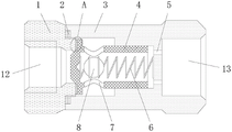
FIG. 1 is a schematic structural view of the present invention;
FIG. 2 is an enlarged schematic view of the structure at A of the present invention;
FIG. 3 is a left side view schematic diagram of the valve core of the present invention;
fig. 4 is the structure schematic diagram of the right side view of the base of the liquid inlet valve of the utility model.
In the figure: 1. a liquid inlet valve base; 2. a first gasket; 3. a liquid outlet valve shell; 4. a valve core; 5. a through hole; 6. a spring; 7. a drain hole; 8. a flow guide sphere; 9. a sealing convex ring; 10. a groove; 11. a second gasket; 12. a liquid inlet; 13. and a liquid outlet.
Detailed Description
The technical solutions in the embodiments of the present invention will be described clearly and completely with reference to the drawings in the embodiments of the present invention, and it is obvious that the described embodiments are only some embodiments of the present invention, not all embodiments. Based on the embodiments in the present invention, all other embodiments obtained by a person skilled in the art without creative efforts all belong to the protection scope of the present invention.
Referring to fig. 1-4, a sealing structure of a check valve includes a liquid inlet valve base 1 and a liquid outlet valve housing 3, a sealing convex ring 9 is disposed on the right side of the liquid inlet valve base 1, a spring 6 is fixedly connected to the right side of the inner cavity of the liquid outlet valve housing 3, a flow guide ball 8 is disposed at the left end of the spring 6, a valve core 4 is fixedly connected to the other side of the spring 6, a groove 10 is disposed on the left side of the valve core 4, a second sealing pad 11 is fixedly connected to the inner side of the groove 10, liquid guide holes 7 are disposed at the top and the bottom of the left end of the liquid outlet valve housing 3, and two seals can be added while the valve core 4 is sealed on the basis through the second sealing pad 11, the groove 10, the valve core 4 and the sealing convex ring 9, so that the check valve achieves the purposes of good sealing performance and leakage prevention.
The inner surface of the liquid inlet valve base 1 is provided with a liquid inlet 12, the right end of the liquid inlet valve base 1 is in threaded connection with a liquid outlet valve shell 3, and a first sealing gasket 2 is arranged between the liquid inlet valve base 1 and the liquid outlet valve shell 3.
The inner surface of the right end of the liquid outlet valve shell 3 is provided with a liquid outlet 13, and the left side of the inner cavity of the liquid outlet 13 is provided with a through hole 5.
The number of the through holes 5 is multiple, and included angles between every two adjacent through holes 5 are equal.
The number of the convex sealing rings 9 is two, and the positions of the convex sealing rings 9 and the second sealing gasket 11 correspond to each other.
During the use, through the cooperation of the first sealed pad 2, make sealing connection between feed liquor valve base 1 and the play liquid valve casing 3, and simultaneously, inlet 12 is blockked up to the left end of case 4, and under the assistance of spring 6, sealed protruding ring 9 can push the sealed pad 11 of second, make the sealed pad 11 indent of second and parcel sealed protruding ring 9, thereby two seal structure has been increased, after liquid gets into this check valve through inlet 12, after its liquid pressure is greater than spring 6 tension, liquid can push case 4 and move right, and compression spring 6, and then liquid can get into liquid outlet 13 through-hole 5 with the assistance of water conservancy diversion spheroid 7, on the contrary, when liquid gets into in the play liquid valve casing 3 through liquid outlet 13, spring 6 can be sealed once more after resuming tension, thereby avoided the adverse current of liquid, people's user demand has been satisfied.
Although embodiments of the present invention have been shown and described, it will be appreciated by those skilled in the art that changes, modifications, substitutions and alterations can be made in these embodiments without departing from the principles and spirit of the invention, the scope of which is defined in the appended claims and their equivalents.
Claims (4)
1. The utility model provides a seal structure of check valve, includes feed liquor valve base (1) and play liquid valve housing (3), its characterized in that: the liquid inlet valve is characterized in that a sealing convex ring (9) is arranged on the right side of the liquid inlet valve base (1), a spring (6) is fixedly connected to the right side of an inner cavity of the liquid outlet valve shell (3), a flow guide ball body (8) is arranged at the left end of the spring (6), a valve core (4) is fixedly connected to the other side of the spring (6), a groove (10) is formed in the left side of the valve core (4), a second sealing gasket (11) is fixedly connected to the inner side of the groove (10), liquid guide holes (7) are formed in the top and the bottom of the left end of the liquid outlet valve shell (3), a liquid inlet (12) is formed in the inner surface of the liquid inlet valve base (1), a liquid outlet valve shell (3) is connected to the right end of the liquid inlet valve base (1) through threads, and a first sealing gasket (2) is arranged between the liquid inlet valve base (1) and the liquid outlet valve shell (3).
2. A sealing structure of a check valve according to claim 1, characterized in that: liquid outlet (13) have been seted up to the internal surface of liquid outlet valve casing (3) right-hand member, through-hole (5) have been seted up on the left side of liquid outlet (13) inner chamber.
3. A sealing structure of a check valve according to claim 2, wherein: the number of the through holes (5) is multiple, and included angles between every two adjacent through holes (5) are equal.
4. A sealing structure of a check valve according to claim 1, characterized in that: the number of the sealing convex rings (9) is two, and the positions of the sealing convex rings (9) and the positions of the second sealing gaskets (11) correspond to each other.
Priority Applications (1)
| Application Number | Priority Date | Filing Date | Title |
|---|---|---|---|
| CN202221743043.5U CN217951319U (en) | 2022-07-07 | 2022-07-07 | Sealing structure of one-way valve |
Applications Claiming Priority (1)
| Application Number | Priority Date | Filing Date | Title |
|---|---|---|---|
| CN202221743043.5U CN217951319U (en) | 2022-07-07 | 2022-07-07 | Sealing structure of one-way valve |
Publications (1)
| Publication Number | Publication Date |
|---|---|
| CN217951319U true CN217951319U (en) | 2022-12-02 |
Family
ID=84220594
Family Applications (1)
| Application Number | Title | Priority Date | Filing Date |
|---|---|---|---|
| CN202221743043.5U Expired - Fee Related CN217951319U (en) | 2022-07-07 | 2022-07-07 | Sealing structure of one-way valve |
Country Status (1)
| Country | Link |
|---|---|
| CN (1) | CN217951319U (en) |
Cited By (1)
| Publication number | Priority date | Publication date | Assignee | Title |
|---|---|---|---|---|
| CN117985349A (en) * | 2024-04-03 | 2024-05-07 | 山东凯布尔化工有限公司 | Closed tank for durene feeding |
-
2022
- 2022-07-07 CN CN202221743043.5U patent/CN217951319U/en not_active Expired - Fee Related
Cited By (2)
| Publication number | Priority date | Publication date | Assignee | Title |
|---|---|---|---|---|
| CN117985349A (en) * | 2024-04-03 | 2024-05-07 | 山东凯布尔化工有限公司 | Closed tank for durene feeding |
| CN117985349B (en) * | 2024-04-03 | 2024-05-31 | 山东凯布尔化工有限公司 | Closed tank for durene feeding |
Similar Documents
| Publication | Publication Date | Title |
|---|---|---|
| CN208687000U (en) | A kind of two way seal floating hard seal ball valve spring is against pressure and structure | |
| CN216477779U (en) | Diaphragm compressor cylinder sealing structure, compression cylinder and diaphragm compressor | |
| CN214743565U (en) | Check valve | |
| CN114776578A (en) | Leakage-proof internal circulation type plunger pump | |
| CN201215192Y (en) | Structure improved ball-valve | |
| CN211289194U (en) | Plug type sealing device for replacing pipeline inlet and outlet maintenance valve | |
| CN220416217U (en) | Spring-free rubber plug sealing ring | |
| CN204140344U (en) | A kind of sealing configuration of diaphragm pump | |
| CN217421504U (en) | Leakage-proof internal circulation type plunger pump | |
| CN213270530U (en) | Split type cylinder body that oil-gas mixture used | |
| CN215806546U (en) | Check valve for preventing leakage | |
| CN215806377U (en) | Eccentric butterfly valve with double-seal structure | |
| CN214063975U (en) | Poppet valve packing chamber sealing structure | |
| CN209213061U (en) | A kind of control water non-return valve | |
| CN207960931U (en) | A kind of water conservancy diversion end face seal slot | |
| CN222046633U (en) | A stop valve | |
| CN212717962U (en) | Water leakage prevention O-shaped ring of air extraction valve operating seat | |
| CN220956828U (en) | Sealing structure applied to cartridge valve | |
| CN222543007U (en) | Adjustable sealing ring | |
| CN218913712U (en) | Sealing ring | |
| CN223399268U (en) | High-density electromagnetic valve core | |
| CN218992468U (en) | A check valve with anti-leakage effect | |
| CN220102176U (en) | High-pressure diversion check valve | |
| CN217301764U (en) | Long-life unloading valve | |
| CN216009755U (en) | High-performance fluorine-lined gate valve |
Legal Events
| Date | Code | Title | Description |
|---|---|---|---|
| GR01 | Patent grant | ||
| GR01 | Patent grant | ||
| CF01 | Termination of patent right due to non-payment of annual fee |
Granted publication date: 20221202 |
|
| CF01 | Termination of patent right due to non-payment of annual fee |