CN217944878U - Coaxial drive arrangement and vehicle - Google Patents
Coaxial drive arrangement and vehicle Download PDFInfo
- Publication number
- CN217944878U CN217944878U CN202222318148.2U CN202222318148U CN217944878U CN 217944878 U CN217944878 U CN 217944878U CN 202222318148 U CN202222318148 U CN 202222318148U CN 217944878 U CN217944878 U CN 217944878U
- Authority
- CN
- China
- Prior art keywords
- planetary gear
- differential
- gear train
- gear
- planetary
- Prior art date
- Legal status (The legal status is an assumption and is not a legal conclusion. Google has not performed a legal analysis and makes no representation as to the accuracy of the status listed.)
- Active
Links
Images




Landscapes
- Retarders (AREA)
Abstract
本实用新型提供一种同轴驱动装置及车辆,其中所述同轴驱动装置包括:壳体支撑架、驱动电机、复合行星架、NW行星排轮系以及差速轮系;其中,驱动电机安装于所述壳体支撑架上;复合行星架转动安装于所述壳体支撑架上;NW行星排轮系安装于所述复合行星架上,所述NW行星排轮系内部设置有回转中心内腔,所述NW行星排轮系与所述驱动电机连接;差速轮系安装于所述复合行星架上、且位于所述回转中心腔内,差速轮系运行轨迹的外径大于NW行星排轮系运行轨迹的内径;所述驱动电机、所述复合行星架、所述NW行星排轮系以及所述差速轮系同轴设置。本实用新型用以改善现有的同轴驱动装置存在的径向及轴向尺寸大的问题。

The utility model provides a coaxial driving device and a vehicle, wherein the coaxial driving device includes: a housing support frame, a driving motor, a composite planet carrier, an NW planetary gear train and a differential gear train; wherein the driving motor is installed on the housing support frame; the composite planetary frame is rotatably installed on the housing support frame; the NW planetary gear train is installed on the composite planetary frame, and the inside of the NW planetary gear train is provided with a center of rotation cavity, the NW planetary gear train is connected to the drive motor; the differential gear train is installed on the composite planet carrier and is located in the center of rotation cavity, and the outer diameter of the differential gear train track is larger than that of the NW planet The inner diameter of the running track of the gear train; the driving motor, the compound planetary carrier, the NW planetary gear train and the differential gear train are arranged coaxially. The utility model is used to improve the problem of large radial and axial dimensions existing in the existing coaxial driving device.
Description
技术领域technical field
本实用新型涉及车辆驱动领域,具体涉及一种同轴驱动装置及车辆。The utility model relates to the field of vehicle drive, in particular to a coaxial drive device and a vehicle.
背景技术Background technique
随着全球碳排放政策的进一步加严以及国家纯电动新能源汽车推广力度的加大,需要寻求性能和布置更好的电驱动总成,以应用于纯电车型的开发。目前电驱动动力总成分为平行轴和同轴两大类,同轴具有布置方便,尤其行星排同轴还具有功率密度高等特点。然而现有的同轴驱动装置存在径向尺寸大、轴向尺寸大的问题。With the further tightening of global carbon emission policies and the promotion of pure electric new energy vehicles in the country, it is necessary to seek electric drive assemblies with better performance and layout to apply to the development of pure electric vehicles. At present, the electric drive powertrain is divided into two categories: parallel shaft and coaxial. The coaxial is easy to arrange, especially the coaxial planetary row has the characteristics of high power density. However, the existing coaxial driving device has the problem of large radial dimension and large axial dimension.
实用新型内容Utility model content
鉴于以上现有技术的缺点,本实用新型提供一种同轴驱动装置及车辆,以改善现有的同轴驱动装置存在的径向及轴向尺寸大的问题。In view of the above shortcomings of the prior art, the utility model provides a coaxial drive device and a vehicle to improve the problem of large radial and axial dimensions existing in the existing coaxial drive device.
为实现上述目的及其它相关目的,本实用新型提供一种同轴驱动装置,包括:壳体支撑架、驱动电机、复合行星架、NW行星排轮系以及差速轮系;其中,驱动电机安装于所述壳体支撑架上;复合行星架转动安装于所述壳体支撑架上;NW行星排轮系安装于所述复合行星架上,所述NW行星排轮系内部设置有回转中心内腔,所述NW行星排轮系与所述驱动电机连接;差速轮系安装于所述复合行星架上、且位于所述回转中心腔内,差速轮系运行轨迹的外径大于NW行星排轮系运行轨迹的内径;所述驱动电机、所述复合行星架、所述NW行星排轮系以及所述差速轮系同轴设置。In order to achieve the above purpose and other related purposes, the utility model provides a coaxial driving device, including: a housing support frame, a driving motor, a composite planet carrier, an NW planetary gear train and a differential gear train; wherein, the driving motor is installed on the housing support frame; the composite planetary frame is rotatably installed on the housing support frame; the NW planetary gear train is installed on the composite planetary frame, and the inside of the NW planetary gear train is provided with a center of rotation cavity, the NW planetary gear train is connected to the drive motor; the differential gear train is installed on the compound planet carrier and is located in the center of rotation cavity, and the outer diameter of the differential gear train track is larger than that of the NW planet The inner diameter of the running track of the gear train; the drive motor, the compound planetary carrier, the NW planetary gear train and the differential gear train are arranged coaxially.
在本实用新型一实施方式中,所述差速轮系包括:差速行星轮以及半轴齿轮,所述差速行星轮转动安装于所述复合行星架上,所述差速行星轮与所述半轴齿轮啮合。In one embodiment of the present utility model, the differential gear train includes: a differential planetary gear and a side gear, the differential planetary gear is rotatably mounted on the composite planet carrier, and the differential planetary gear and the The side gear meshes.
在本实用新型一实施方式中,所述NW行星排轮系包括:太阳轮、塔式双联齿行星轮以及内齿圈,所述太阳轮与所述驱动电机的输出轴连接,所述塔式双联齿行星轮与所述太阳轮啮合,所述内齿圈与所述塔式双联齿行星轮啮合。In one embodiment of the present utility model, the NW planetary gear train includes: a sun gear, a tower type double-teeth planetary gear and an inner ring gear, the sun gear is connected to the output shaft of the driving motor, and the tower The double-toothed planetary gear meshes with the sun gear, and the ring gear meshes with the double-toothed planetary gear of the tower type.
在本实用新型一实施方式中,所述内齿圈安装于所述壳体支撑架上,所述复合行星架位于所述内齿圈的内部。In one embodiment of the present utility model, the inner ring gear is installed on the housing support frame, and the compound planet carrier is located inside the inner ring gear.
在本实用新型一实施方式中,所述差速轮系包括若干个差速行星轮,所述NW行星排轮系包括若干个塔式双联齿行星轮,所述塔式双联齿行星轮的数量与所述差速行星轮的数量相对应。In one embodiment of the present invention, the differential gear train includes several differential planetary gears, the NW planetary gear train includes several tower-type double-tooth planetary gears, and the tower-type double-tooth planetary gears The number corresponds to the number of the differential planetary gears.
在本实用新型一实施方式中,所述塔式双联齿行星轮的数量与所述差速行星轮的数量相等。In an embodiment of the present utility model, the number of the tower-type double-toothed planetary gears is equal to the number of the differential planetary gears.
在本实用新型一实施方式中,每一所述塔式双联齿行星轮包括大行星轮与小行星轮,所述大行星轮与所述小行星轮同轴连接,所述大行星轮与所述太阳轮啮合,所述小行星轮与所述内齿圈啮合,所述小行星轮与所述差速行星轮交替等间隔布置。In one embodiment of the present invention, each of the tower-type double-toothed planetary gears includes a large planetary gear and a small planetary gear, the large planetary gear and the small planetary gear are coaxially connected, and the large planetary gear and the small planetary gear are coaxially connected. The sun gear is meshed, the small planetary gear is meshed with the ring gear, and the small planetary gear and the differential planetary gear are alternately and equally spaced.
在本实用新型一实施方式中,所述复合行星架包括行星架壳体,所述行星架壳体上设置有第一行星架支撑位、大行星轮支撑位、小行星轮支撑位、太阳轮支撑位以及差速行星轮支撑位。In one embodiment of the present invention, the composite planetary carrier includes a planetary carrier housing, and the planetary carrier housing is provided with a first planetary carrier support position, a large planetary wheel support position, a small planetary wheel support position, a sun gear Support position and differential planetary gear support position.
在本实用新型一实施方式中,所述壳体支撑架包括:壳体,所述壳体上设置有第二行星架支撑位、第一电机转子支撑位、第二电机转子支撑位、内齿圈支撑位以及电机定子支撑位。In one embodiment of the present invention, the housing support frame includes: a housing, on which are provided a second planet carrier support position, a first motor rotor support position, a second motor rotor support position, internal teeth Ring support position and motor stator support position.
一种车辆,所述车辆上设置有所述的同轴驱动装置。A vehicle, the vehicle is provided with the coaxial drive device.
本实用新型同轴驱动装置,差速轮系位于NW行星排轮系的回转中心腔内,差速轮系嵌入行星排内部实现较小的轴向尺寸,较小的轴向尺寸有利于整车驱动半轴的布置,有利于前轮转向机的布置。同时由于差速轮系运行轨迹的外径大于NW行星排轮系运行轨迹的内径,使得整个装置的径向尺寸变小,较小的径向尺寸可以带来较高的离地间隙,较自由的Z向布置空间,较方便集成电机控制器。The coaxial drive device of the utility model, the differential gear train is located in the slewing center cavity of the NW planetary gear train, and the differential gear train is embedded inside the planetary gear train to achieve a smaller axial size, which is beneficial to the whole vehicle The layout of the driving half shaft is beneficial to the layout of the front wheel steering gear. At the same time, because the outer diameter of the running track of the differential gear train is larger than the inner diameter of the running track of the NW planetary gear train, the radial size of the entire device becomes smaller, and the smaller radial size can bring higher ground clearance and more freedom. The Z-direction layout space is more convenient to integrate the motor controller.
附图说明Description of drawings
为了更清楚地说明本实用新型实施例或现有技术中的技术方案,下面将对实施例或现有技术描述中所需要使用的附图作简单地介绍,显而易见地,下面描述中的附图仅仅是本实用新型的一些实施例,对于本领域普通技术人员来讲,在不付出创造性劳动的前提下,还可以根据这些附图获得其他的附图。In order to more clearly illustrate the technical solutions in the embodiments of the present invention or the prior art, the following will briefly introduce the accompanying drawings that need to be used in the description of the embodiments or the prior art. Obviously, the accompanying drawings in the following description These are only some embodiments of the utility model, and those skilled in the art can also obtain other drawings based on these drawings without creative work.
图1为本实用新型所述的同轴驱动装置于一实施方式中的原理示意图;Fig. 1 is a schematic diagram of the principle of the coaxial driving device described in the present invention in an embodiment;
图2为本实用新型所述的NW行星排轮系于一实施方式中的原理示意图;Fig. 2 is a schematic diagram of the principle of the NW planetary gear train described in the present invention in an embodiment;
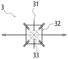
图3为本实用新型所述的差速轮系于一实施方式中的原理示意图;Fig. 3 is a schematic diagram of the principle of the differential gear train described in the present invention in an embodiment;
图4为本实用新型所述的行星轮布置图;Fig. 4 is the arrangement diagram of the planetary gear described in the utility model;
图5为本实用新型所述的复合行星架于一实施方式中的原理示意图;Fig. 5 is a schematic diagram of the principle of the composite planetary carrier described in the present invention in an embodiment;
图6为本实用新型所述的壳体支撑架于一实施方式中的原理示意图;Fig. 6 is a schematic diagram of the principle of the housing support frame in an embodiment of the present invention;
元件标号说明Component designation description
1、同轴驱动装置;2、NW行星排轮系;21、太阳轮;22、塔式双联齿行星轮;221、大行星轮;222、小行星轮;23、内齿圈;3、差速轮系;31、差速行星轮;32、半轴齿轮;33、球接;4、复合行星架;41、行星架壳体;42、第一行星架支撑位;43、小行星轮支撑位;44、大行星轮支撑位;45、太阳轮支撑位;46、差速行星轮支撑位;5、驱动电机;51、电机定子;52、电机转子;6、壳体支撑架;61、第二行星架支撑位;62、第一电机转子支撑位;63、第二电机转子支撑位;64、内齿圈支撑位;65、电机定子支撑位。1. Coaxial drive device; 2. NW planetary gear train; 21. Sun gear; 22. Tower type double gear planetary gear; 221. Large planetary gear; 222. Small planetary gear; 23. Internal gear; 3. Differential gear train; 31. Differential planetary gear; 32. Half shaft gear; 33. Ball joint; 4. Composite planetary carrier; 41. Planetary carrier shell; 42. First planetary carrier support position; 43. Small planetary wheel Support position; 44, large planetary wheel support position; 45, sun gear support position; 46, differential planetary wheel support position; 5, drive motor; 51, motor stator; 52, motor rotor; 6, housing support frame; 61 , the second planet carrier support position; 62, the first motor rotor support position; 63, the second motor rotor support position; 64, the inner ring gear support position; 65, the motor stator support position.
具体实施方式Detailed ways
以下通过特定的具体实例说明本实用新型的实施方式,本领域技术人员可由本说明书所揭露的内容轻易地了解本实用新型的其它优点与功效。本实用新型还可以通过另外不同的具体实施方式加以实施或应用,本说明书中的各项细节也可以基于不同观点与应用,在没有背离本实用新型的精神下进行各种修饰或改变。需说明的是,在不冲突的情况下,以下实施例及实施例中的特征可以相互组合。还应当理解,本实用新型实施例中使用的术语是为了描述特定的具体实施方案,而不是为了限制本实用新型的保护范围。下列实施例中未注明具体条件的试验方法,通常按照常规条件,或者按照各制造商所建议的条件。The implementation of the present utility model is described below through specific examples, and those skilled in the art can easily understand other advantages and effects of the present utility model from the content disclosed in this specification. The utility model can also be implemented or applied through other different specific implementation modes, and the details in this specification can also be modified or changed based on different viewpoints and applications without departing from the spirit of the utility model. It should be noted that, in the case of no conflict, the following embodiments and features in the embodiments can be combined with each other. It should also be understood that the terminology used in the embodiments of the present utility model is for describing a specific implementation, but not for limiting the protection scope of the present utility model. The test methods for which specific conditions are not indicated in the following examples are usually in accordance with conventional conditions, or in accordance with the conditions suggested by each manufacturer.
须知,本说明书中所引用的如“上”、“下”、“左”、“右”、“中间”及“一”等的用语,亦仅为便于叙述的明了,而非用以限定本实用新型可实施的范围,其相对关系的改变或调整,在无实质变更技术内容下,当亦视为本实用新型可实施的范畴。It should be noted that terms such as "upper", "lower", "left", "right", "middle" and "one" quoted in this specification are only for the convenience of description and are not used to limit this specification. The practicable range of the utility model, and the change or adjustment of its relative relationship, without any substantial change in the technical content, shall also be regarded as the practicable scope of the utility model.
请参阅图1至图4,为实现上述目的及其它相关目的,本实用新型提供一种同轴驱动装置1,包括:壳体支撑架6、驱动电机5、复合行星架4、NW行星排轮系2以及差速轮系3;其中,驱动电机5安装于所述壳体支撑架6上;复合行星架4转动安装于所述壳体支撑架6上;NW行星排轮系2安装于所述复合行星架4上,所述NW行星排轮系2内部设置有回转中心内腔,所述NW行星排轮系2与所述驱动电机5连接;差速轮系3安装于所述复合行星架4上、且位于所述回转中心腔内,差速轮系3运行轨迹的外径大于NW行星排轮系2运行轨迹的内径;所述驱动电机5、所述复合行星架4、所述NW行星排轮系2以及所述差速轮系3同轴设置。Please refer to Fig. 1 to Fig. 4, in order to achieve the above purpose and other related purposes, the utility model provides a
请参阅图3,在本实用新型一实施方式中,所述差速轮系3包括:差速行星轮31以及半轴齿轮32,所述差速行星轮31转动安装于所述复合行星架4上,所述差速行星轮31与所述半轴齿轮32啮合。Please refer to FIG. 3 , in one embodiment of the present utility model, the
请参阅图2及图4,在本实用新型一实施方式中,所述NW行星排轮系2包括:太阳轮21、塔式双联齿行星轮22以及内齿圈23,所述太阳轮21与所述驱动电机5的输出轴连接,所述塔式双联齿行星轮22与所述太阳轮21啮合,所述内齿圈23与所述塔式双联齿行星轮22啮合。Please refer to Fig. 2 and Fig. 4, in one embodiment of the present utility model, the NW
请参阅图1至图4,NW行星排轮系2同轴于差速轮系3、复合行星架4和驱动电机5布置,且其回转中心内腔内设置有差速轮系3。NW行星排轮系2包含太阳轮21、塔式双联齿行星轮22和内齿圈23。太阳轮21以一体旋转的方式与电机转子52相联,联接方式包含花键即太阳轮以花键形式设置与电机转子之上、一体轴即太阳转子上加工有太阳轮齿形等形式。塔式双联齿行星轮22包含大行星轮221和小行星论222,其数量与差速轮系3的差速行星轮31数量相等,优选数量为3,且在周向均匀布置,大行星轮221和小行星轮222以一体旋转的方式连接,大行星轮221与太阳轮21相互啮合,小行星轮222与内齿圈23相互啮合,其两侧通过滚动轴承形式支撑与复合行星架4之上,两侧分别设置于塔式行星轮支撑位43和塔式行星轮支撑位44之上。内齿圈23以周向和轴向固定连接方式设置于壳体支撑架6之上,为了实现与小行星轮222啮合时的浮动均载,采用内齿圈浮动方式,即内齿圈的径向允许一定浮动。所述复合行星架4位于所述内齿圈23的内部。Please refer to Fig. 1 to Fig. 4, the NW
请参阅图1、图3及图4,在本实用新型一实施方式中,所述差速轮系3包括若干个差速行星轮31,所述NW行星排轮系2包括若干个塔式双联齿行星轮22,所述塔式双联齿行星轮22的数量与所述差速行星轮31的数量相对应。相对应可以是所述差速行星轮31的数量是所述塔式双联齿行星轮22的数量的整数倍,所述整数大于等于1。Please refer to Fig. 1, Fig. 3 and Fig. 4, in one embodiment of the present invention, the
请参阅图1至图4,差速轮系3同轴于NW行星排轮系2、复合行星架4和驱动电机5布置,其通过滑动轴承形式支撑与复合行星架4之上,且位于NW行星排轮系2回转中心内腔,其包含差速行星轮31、半轴齿轮32和球接33,差速行星轮31数量与塔式双联齿行星轮22数量相等,优选数量为3,且在周向与塔式双联齿行星轮22交替等间隔布置,其以相对旋转的方式支撑于复合行星架4的差速行星轮支撑孔46和球接33之上,连接方式可以为滚动轴承或者滑动轴承,优选为滑动轴承,半轴齿轮32与所有的差速行星轮31相互啮合,啮合齿形优选为直齿锥齿轮,把来自于驱动电机5的动力输出至轮端,或者把来自于轮端的能量回馈值驱动电机5。通过采用行星排行星轮数量与差速器星轮数量相等的设计,使两者的行星轮可以在周向等角度间隔布置,实现较好的动平衡;同时还能使行星排的行星轮可以避开复合行星架的干涉,利用差速器行星轮的窗口空间,实现较小的径向尺寸。Please refer to Fig. 1 to Fig. 4, the
请参阅图2及图3,在本实用新型一实施方式中,每一所述塔式双联齿行星轮22包括大行星轮221与小行星轮222,所述大行星轮221与所述小行星轮222同轴连接,所述大行星轮221与所述太阳轮21啮合,所述小行星轮222与所述内齿圈23啮合。相邻两个差速行星轮31之间形成间隙,若干个差速行星轮31形成若干个间隙,小行星轮至少部分位于对应的间隙中。当所述塔式双联齿行星轮22的数量与所述差速行星轮31的数量相等时,即小行星轮的数量与差速行星轮222相等时,小行星轮222与所述差速行星轮31交替等间隔布置。Please refer to Fig. 2 and Fig. 3, in one embodiment of the present utility model, each described tower type double gear
请参阅图5,在本实用新型一实施方式中,所述复合行星架4包括行星架壳体41,所述行星架壳体41上设置有第一行星架支撑位42、大行星轮支撑位44、小行星轮支撑位43、太阳轮支撑位45以及差速行星轮支撑位46。Please refer to Fig. 5 , in one embodiment of the present utility model, the composite
请参阅图1、图3及图5,复合行星架4同轴于NW行星排轮系2、差速轮系3和驱动电机5布置,以相对旋转的方式支撑于壳体支撑系统6之上,连接方式优选的为滚动轴承,且在轴向尺寸上基本上与NW行星排轮系2和差速轮系3重合,其包含行星架壳体41、行星架支撑位42、塔式行星轮支撑位43、塔式行星轮支撑位44、太阳轮支撑位45和差速行星轮支撑位46,所有支撑位的支撑形式优选为滚动轴承支撑。行星架壳体41提供所有支撑位的集成,行星架支撑位42和太阳轮支撑位45同轴于NW行星排轮系2、差速轮系3和驱动电机5布置,行星架支撑位42以滚动轴承方式与壳体支撑系统6连接,太阳轮支撑位45以滚动轴承方式与太阳轮21连接,塔式行星轮支撑位43和塔式行星轮支撑位44数量与塔式双联齿行星轮22相等且同轴布置,支撑于塔式双联齿行星轮22两侧,差速行星轮支撑位46数量与差速行星轮31数量相等,为差速行星轮31提供支撑。Please refer to Fig. 1, Fig. 3 and Fig. 5, the composite
请参阅图1及图6,驱动电机5同轴于NW行星排轮系2、差速轮系3和复合行星架4布置,其包含电机定子51和电机转子52,电机定子51通过电机定子支撑位65以同轴固定方式设置于壳体支撑系统6之上,连接方式优选为过盈连接,电机转子52通过电机转子支撑位62和电机转子支撑位63以相对旋转方式设置于壳体支撑系统6之上,支撑形式优选为滚动轴承连接。Please refer to Fig. 1 and Fig. 6, the
请参阅图6,在本实用新型一实施方式中,所述壳体支撑架6包括:壳体,所述壳体上设置有第二行星架支撑位61、第一电机转子支撑位62、第二电机转子支撑位63、内齿圈支撑位64以及电机定子支撑位65。壳体可由2~4个分壳体组成,优选为3部分。Please refer to Fig. 6. In one embodiment of the present utility model, the
对比图1及图2,可知本实用新型较现有驱动装置,由于采用NW行星排轮系2,差速轮系3和复合行星架4共用轴向尺寸,差速轮系3设置于NW行星排轮系2回转中心内腔内,并同时设置于复合行星架4之上,复合行星架4设置于壳体支撑系统6之上,既满足塔式双联齿行星轮22和差速行星轮31的绕同轴驱动装置1轴线的公转以及绕自身轴线自转的支撑需求,又能实现较小的轴向尺寸,有利于实现较高的功率密度和便于整车的动力总成布置。Comparing Fig. 1 and Fig. 2, it can be seen that the utility model is compared with the existing driving device. Since the NW
对比图1与图4,由于采用塔式双联齿行星轮22和差速行星轮31数量相等,优选为3,可以实现在周向的均匀等间隔布置,极大减小了驱动装置内旋转件的动不平衡量,基于公知,动不平衡在旋转时会产生动不平衡力,对相关零件造成额外疲劳和失效,因此有利于提高动力传递路径上零件的耐久可靠性,同时,基于公知,动不平衡力产生的震动会产生NVH问题,因此本实用新型有利于NVH属性的提升。Comparing Fig. 1 with Fig. 4, since the number of tower-type double-toothed
由于采用塔式双联齿行星轮22与差速行星轮31数量相等且交替布置,因此塔式双联齿行星轮22可以避开差速行星轮支撑位46处的壳体,进而实现较小的径向尺寸,基于公知,较小的径向尺寸意味着更高的功率密度,更好的动力总成布置空间,更高的离地间隙,更好的集成空间,例如与电机控制器或者充电机的集成。Since the number of the tower-type double-toothed
一种车辆,所述车辆上设置有所述的同轴驱动装置。A vehicle, the vehicle is provided with the coaxial drive device.
本实用新型同轴驱动装置,差速轮系3位于NW行星排轮系2的回转中心腔内,差速轮系3嵌入行星排内部实现较小的轴向尺寸,较小的轴向尺寸有利于整车驱动半轴的布置,有利于前轮转向机的布置。同时由于差速轮系3运行轨迹的外径大于NW行星排轮系2运行轨迹的内径,使得整个装置的径向尺寸变小,较小的径向尺寸可以带来较高的离地间隙,较自由的Z向布置空间,较方便集成电机控制器。所以,本实用新型有效克服了现有技术中的一些实际问题从而有很高的利用价值和使用意义。In the coaxial driving device of the utility model, the
上述实施例仅例示性说明本实用新型的原理及其功效,而非用于限制本实用新型。任何熟悉此技术的人士皆可在不违背本实用新型的精神及范畴下,对上述实施例进行修饰或改变。因此,举凡所属技术领域中具有通常知识者在未脱离本实用新型所揭示的精神与技术思想下所完成的一切等效修饰或改变,仍应由本实用新型的权利要求所涵盖。The above-mentioned embodiments only illustrate the principles and effects of the present utility model, but are not intended to limit the present utility model. Anyone familiar with this technology can modify or change the above-mentioned embodiments without departing from the spirit and scope of the present invention. Therefore, all equivalent modifications or changes made by those with ordinary knowledge in the technical field without departing from the spirit and technical ideas disclosed in the utility model should still be covered by the claims of the utility model.
Claims (10)
Priority Applications (1)
| Application Number | Priority Date | Filing Date | Title |
|---|---|---|---|
| CN202222318148.2U CN217944878U (en) | 2022-08-31 | 2022-08-31 | Coaxial drive arrangement and vehicle |
Applications Claiming Priority (1)
| Application Number | Priority Date | Filing Date | Title |
|---|---|---|---|
| CN202222318148.2U CN217944878U (en) | 2022-08-31 | 2022-08-31 | Coaxial drive arrangement and vehicle |
Publications (1)
| Publication Number | Publication Date |
|---|---|
| CN217944878U true CN217944878U (en) | 2022-12-02 |
Family
ID=84211797
Family Applications (1)
| Application Number | Title | Priority Date | Filing Date |
|---|---|---|---|
| CN202222318148.2U Active CN217944878U (en) | 2022-08-31 | 2022-08-31 | Coaxial drive arrangement and vehicle |
Country Status (1)
| Country | Link |
|---|---|
| CN (1) | CN217944878U (en) |
Cited By (1)
| Publication number | Priority date | Publication date | Assignee | Title |
|---|---|---|---|---|
| CN115195435A (en) * | 2022-08-31 | 2022-10-18 | 浙江极氪智能科技有限公司 | Coaxial drive arrangement and vehicle |
-
2022
- 2022-08-31 CN CN202222318148.2U patent/CN217944878U/en active Active
Cited By (1)
| Publication number | Priority date | Publication date | Assignee | Title |
|---|---|---|---|---|
| CN115195435A (en) * | 2022-08-31 | 2022-10-18 | 浙江极氪智能科技有限公司 | Coaxial drive arrangement and vehicle |
Similar Documents
| Publication | Publication Date | Title |
|---|---|---|
| CN106555844B (en) | Power driving system and vehicle with same | |
| CN100467909C (en) | Coaxial counter-rotating high-speed planetary gear transmission | |
| CN106555851B (en) | Differentials, Powertrains and Vehicles | |
| CN108501672A (en) | Power drive system | |
| JP2011102639A (en) | Reduction gear for electric motor | |
| CN113752821A (en) | A deceleration mechanism of a high-speed wheel motor drive system based on a compound planetary gear train | |
| CN105873783A (en) | Drive device for hybrid vehicle | |
| CN205331352U (en) | Spur gear differential mechanism | |
| CN106555845A (en) | Differential mechanism, power drive system and vehicle | |
| CN106553527A (en) | Differential mechanism, power drive system and vehicle | |
| CN106555858B (en) | Power-driven system and vehicle with it | |
| CN102230519B (en) | Face gear planetary gearbox | |
| CN106555855A (en) | Differential mechanism, power drive system and vehicle | |
| CN106553528B (en) | Power drive system and vehicle having the same | |
| CN115217909A (en) | Large-reduction-ratio speed reducer | |
| CN103660929B (en) | Electric vehicle transmission system | |
| CN216343711U (en) | A robot joint deceleration mechanism based on planetary gear train | |
| CN116985626A (en) | Motor drive assembly, automobile transmission system and automobile | |
| CN106555854A (en) | Power-driven system and the vehicle with which | |
| CN106555849B (en) | Power driving system and vehicle with same | |
| CN207015161U (en) | Power assembly of electric automobile | |
| CN106553532A (en) | Power-driven system and the vehicle with which | |
| CN109910605A (en) | Powerplants and Electric Vehicles | |
| CN216231672U (en) | a vehicle drive | |
| CN106553529B (en) | Differential mechanism, power drive system and vehicle |
Legal Events
| Date | Code | Title | Description |
|---|---|---|---|
| GR01 | Patent grant | ||
| GR01 | Patent grant |