CN217933363U - High-frequency transformer with waterproof cover - Google Patents
High-frequency transformer with waterproof cover Download PDFInfo
- Publication number
- CN217933363U CN217933363U CN202221164489.2U CN202221164489U CN217933363U CN 217933363 U CN217933363 U CN 217933363U CN 202221164489 U CN202221164489 U CN 202221164489U CN 217933363 U CN217933363 U CN 217933363U
- Authority
- CN
- China
- Prior art keywords
- waterproof case
- frequency transformer
- waterproof
- bottom plate
- top surface
- Prior art date
- Legal status (The legal status is an assumption and is not a legal conclusion. Google has not performed a legal analysis and makes no representation as to the accuracy of the status listed.)
- Expired - Fee Related
Links
Images


Landscapes
- Patch Boards (AREA)
Abstract
本实用新型公开了一种带有防水罩的高频变压器,属于高频变压器技术领域,包括底板,所述底板的顶部设置有安装框,所述安装框的外侧面开设有紧固螺孔。本实用新型中,通过把高频变压器本体安装在底板的底部,且通过紧固螺栓、紧固螺孔以及安装孔的配合把防水壳固定安装在底板的上部,利用底板和防水壳对高频变压器本体进行包裹,使得高频变压器本体不会与雨水相接触,实现对高频变压器本体进行防水的功能,另外通过底板底面开设的下散热孔和防水壳顶面开设的上散热孔使得防水壳的内腔空气自然流通,进而使得高频变压器本体运行产生的热量自然散出,提高了该带有防水罩的高频变压器的实用性。
The utility model discloses a high-frequency transformer with a waterproof cover, which belongs to the technical field of high-frequency transformers, and comprises a bottom plate. The top of the bottom plate is provided with a mounting frame, and the outer surface of the mounting frame is provided with fastening screw holes. In the utility model, by installing the high-frequency transformer body on the bottom of the bottom plate, and fixing the waterproof case on the upper part of the bottom plate through the cooperation of fastening bolts, fastening screw holes and installation holes, the high-frequency The transformer body is wrapped so that the high-frequency transformer body will not be in contact with rainwater, and the function of waterproofing the high-frequency transformer body is realized. In addition, the lower heat dissipation holes opened on the bottom surface of the bottom plate and the upper heat dissipation holes opened on the top surface of the waterproof case make the waterproof case The air in the inner cavity circulates naturally, and then the heat generated by the operation of the high-frequency transformer body is naturally dissipated, which improves the practicability of the high-frequency transformer with a waterproof cover.
Description
技术领域technical field
本实用新型涉及高频变压器技术领域,更具体地说,涉及一种带有防水罩的高频变压器。The utility model relates to the technical field of high-frequency transformers, in particular to a high-frequency transformer with a waterproof cover.
背景技术Background technique
高频变压器是工作频率超过中频(10kHz)的电源变压器,主要用于高频开关电源中作高频开关电源变压器,也有用于高频逆变电源和高频逆变焊机中作高频逆变电源变压器的。高频变压器一般安装在室外,室外环境复杂,高频变压器受到雨水的冲刷和侵蚀,使得高频变压器的表面涂漆老化掉落,缩短了高频变压器的使用寿命,且内部有进水风险,因此我们提出了一种带有防水罩的高频变压器。High-frequency transformer is a power transformer whose working frequency exceeds intermediate frequency (10kHz). It is mainly used as high-frequency switching power transformer in high-frequency switching power supply, and also used as high-frequency inverter in high-frequency inverter power supply and high-frequency inverter welding machine. power transformer. High-frequency transformers are generally installed outdoors, and the outdoor environment is complex. High-frequency transformers are washed and eroded by rainwater, which makes the surface paint of high-frequency transformers age and falls off, shortens the service life of high-frequency transformers, and there is a risk of water ingress inside. Therefore we propose a high-frequency transformer with a waterproof cover.
实用新型内容Utility model content
针对现有技术中存在的问题,本实用新型的目的在于提供一种带有防水罩的高频变压器,它可以实现对高频变压器进行防水的功能。Aiming at the problems existing in the prior art, the purpose of this utility model is to provide a high-frequency transformer with a waterproof cover, which can realize the function of waterproofing the high-frequency transformer.
为解决上述问题,本实用新型采用如下的技术方案:In order to solve the above problems, the utility model adopts the following technical solutions:
一种带有防水罩的高频变压器,包括底板,所述底板的顶部设置有安装框,所述安装框的外侧面开设有紧固螺孔,所述底板的顶面设置有高频变压器本体,所述底板的底面开设有若干个下散热孔,所述底板的顶部且位于安装框的外侧设置有防水壳,所述防水壳的顶面开设有若干个上散热孔,所述防水壳的顶面设置有遮挡机构,所述防水壳的两侧分别固定安装有排风扇,所述防水壳的内壁设置有除潮机构,所述防水壳的外侧开设有安装孔,所述安装孔的位置与紧固螺孔的位置相适配,所述安装孔的内腔套设有紧固螺栓,所述紧固螺栓的端部螺纹插接至紧固螺孔的内腔。A high-frequency transformer with a waterproof cover, including a bottom plate, a mounting frame is provided on the top of the bottom plate, fastening screw holes are provided on the outer surface of the mounting frame, and a high-frequency transformer body is provided on the top surface of the bottom plate , the bottom surface of the bottom plate is provided with several lower cooling holes, the top of the bottom plate and the outside of the installation frame is provided with a waterproof case, the top surface of the waterproof case is provided with several upper cooling holes, the waterproof case The top surface is provided with a shielding mechanism, the two sides of the waterproof case are respectively fixed with exhaust fans, the inner wall of the waterproof case is provided with a dehumidification mechanism, and the outer side of the waterproof case is provided with installation holes, and the positions of the installation holes are in line with the The positions of the fastening screw holes are matched, and the inner cavity of the installation hole is covered with a fastening bolt, and the end of the fastening bolt is threadedly inserted into the inner cavity of the fastening screw hole.
作为本实用新型的一种优选方案,所述遮挡机构包括固定连接在防水壳顶面的基座,所述基座的两侧分别固定连接有限位柱,两个所述限位柱的外侧均套设有挡块,所述挡块的底面与防水壳的顶面相贴合,两个所述挡块的外侧分别固定连接有拉杆,所述拉杆的一端延伸至防水壳的外侧且固定连接有挡板,所述挡板的内侧面与防水壳的外侧面相贴合,所述挡板位于排风扇的外侧,所述基座的两侧分别固定连接有弹簧,所述弹簧的一端与挡块相连接。As a preferred solution of the present invention, the shielding mechanism includes a base fixedly connected to the top surface of the waterproof case, and the two sides of the base are respectively fixedly connected with limiting columns, and the outer sides of the two limiting columns are A stopper is sleeved, the bottom surface of the stopper fits the top surface of the waterproof case, and the outer sides of the two stoppers are respectively fixedly connected with pull rods, and one end of the tie rod extends to the outside of the waterproof case and is fixedly connected with a A baffle, the inner surface of the baffle is attached to the outer surface of the waterproof case, the baffle is located on the outside of the exhaust fan, the two sides of the base are respectively fixedly connected with springs, and one end of the spring is connected to the stopper connect.
作为本实用新型的一种优选方案,所述除潮机构包括固定连接于防水壳内壁的除潮箱,所述除潮箱的正面铰接有门板,所述门板的表面开设有进气孔,所述除潮箱的内腔设置有吸潮棉。As a preferred solution of the present utility model, the dehumidification mechanism includes a dehumidification box fixedly connected to the inner wall of the waterproof case, the front of the dehumidification box is hinged with a door panel, and the surface of the door panel is provided with an air intake hole. The inner cavity of the dehumidification box is provided with moisture-absorbing cotton.
作为本实用新型的一种优选方案,所述防水壳内腔的顶面固定安装有温度传感器,所述防水壳内腔的顶面设置有控制器,所述防水壳内腔的顶面设置有蓄电池。As a preferred solution of the present invention, a temperature sensor is fixedly installed on the top surface of the inner cavity of the waterproof case, a controller is arranged on the top surface of the inner cavity of the waterproof case, and a controller is arranged on the top surface of the inner cavity of the waterproof case storage battery.
作为本实用新型的一种优选方案,所述防水壳的顶部设置有顶罩,所述顶罩的顶面设置有太阳能板,所述太阳能板与蓄电池电性连接。As a preferred solution of the present invention, a top cover is provided on the top of the waterproof case, a solar panel is provided on the top surface of the top cover, and the solar panel is electrically connected to the battery.
作为本实用新型的一种优选方案,所述下散热孔和上散热孔的内腔均设置有过滤网。As a preferred solution of the present utility model, the inner cavities of the lower cooling holes and the upper cooling holes are both provided with filter screens.
作为本实用新型的一种优选方案,所述防水壳的正面铰接有密封门,所述防水壳的内壁与安装框的外侧面相贴合。As a preferred solution of the present invention, a sealed door is hinged on the front of the waterproof case, and the inner wall of the waterproof case is attached to the outer surface of the installation frame.
相比于现有技术,本实用新型的优点在于:Compared with the prior art, the utility model has the advantages of:
(1)本实用新型中,通过把高频变压器本体安装在底板的底部,且通过紧固螺栓、紧固螺孔以及安装孔的配合把防水壳固定安装在底板的上部,利用底板和防水壳对高频变压器本体进行包裹,使得高频变压器本体不会与雨水相接触,实现对高频变压器本体进行防水的功能,另外通过底板底面开设的下散热孔和防水壳顶面开设的上散热孔使得防水壳的内腔空气自然流通,进而使得高频变压器本体运行产生的热量自然散出,提高了该带有防水罩的高频变压器的实用性。(1) In the utility model, by installing the high-frequency transformer body on the bottom of the base plate, and fixing the waterproof case on the upper part of the base plate through the cooperation of fastening bolts, fastening screw holes and mounting holes, the bottom plate and the waterproof case are used Wrap the high-frequency transformer body so that the high-frequency transformer body will not be in contact with rainwater, and realize the waterproof function of the high-frequency transformer body. In addition, the lower heat dissipation holes opened on the bottom surface of the bottom plate and the upper heat dissipation holes opened on the top surface of the waterproof case The air in the inner cavity of the waterproof case can be naturally circulated, and the heat generated by the operation of the high-frequency transformer body can be dissipated naturally, thereby improving the practicability of the high-frequency transformer with the waterproof cover.
(2)本实用新型中,高频变压器本体运行时利用温度传感器实时对防水壳内腔的温度进行监测,当防水壳内腔的温度过高时,利用排风扇吹出的风力吹动挡板、拉杆和挡块向外移动,使得挡块移动到上散热孔的上方对其进行遮挡,排风扇把防水壳内腔的热量排出,并使得外部的空气只能从下散热孔进入防水壳的内腔,利用自下而上的空气流通把高频变压器本体运行时产生的热量快速带走,当防水壳的内腔温度适合高频变压器本体运行时,排风扇关闭,弹簧的弹力拉动挡块复位,使得上散热孔露出与下散热孔配合自然通风,同时挡板对排风扇的排风口进行遮挡,防止灰尘以及杂物进入,实现了自然散热和机械散热自动切换的功能,提高了该带有防水罩的高频变压器的工作质量。(2) In the utility model, the temperature sensor is used to monitor the temperature of the inner cavity of the waterproof case in real time when the high-frequency transformer body is running. And the stopper moves outward, so that the stopper moves to the top of the upper heat dissipation hole to cover it, and the exhaust fan discharges the heat from the inner cavity of the waterproof case, and makes the external air only enter the inner cavity of the waterproof case from the lower heat dissipation hole. Use bottom-up air circulation to quickly take away the heat generated by the high-frequency transformer body during operation. When the inner cavity temperature of the waterproof case is suitable for the operation of the high-frequency transformer body, the exhaust fan is turned off, and the elastic force of the spring pulls the stopper to reset, so that the upper The exposed heat dissipation holes and the lower heat dissipation holes cooperate with natural ventilation. At the same time, the baffle blocks the air outlet of the exhaust fan to prevent dust and sundries from entering, realizing the automatic switching function of natural heat dissipation and mechanical heat dissipation, and improving the performance The working quality of high frequency transformers.
附图说明Description of drawings
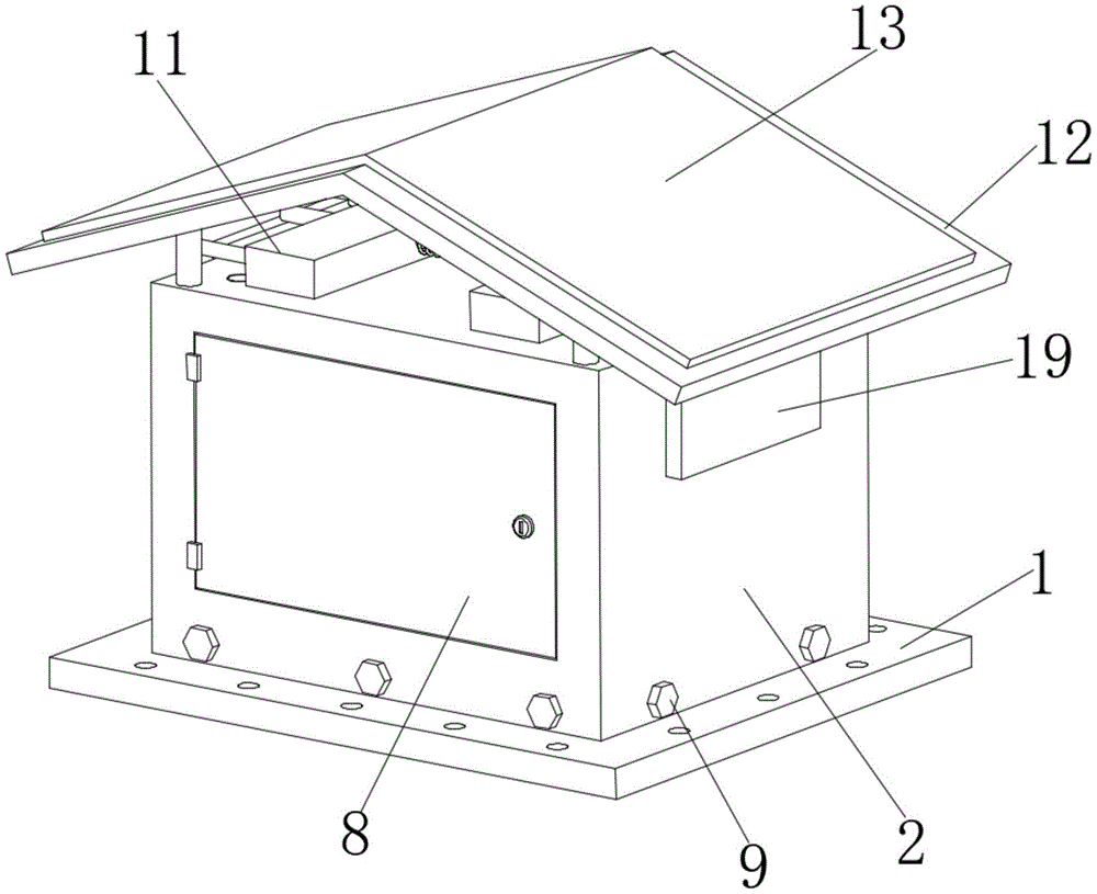
图1为本实用新型的整体结构示意图;Fig. 1 is the overall structural representation of the utility model;
图2为本实用新型底板的结构示意图;Fig. 2 is the structural representation of the utility model bottom plate;
图3为本实用新型防水罩的结构示意图;Fig. 3 is the structural representation of the utility model waterproof cover;
图4为本实用新型遮挡机构的结构示意图;Fig. 4 is a structural schematic diagram of the shielding mechanism of the present invention;
图5为本实用新型防水罩的剖视示意图;Fig. 5 is a schematic cross-sectional view of the utility model waterproof cover;
图6为本实用新型除潮机构的结构示意图。Fig. 6 is a structural schematic diagram of the moisture removal mechanism of the present invention.
图中标号说明:Explanation of symbols in the figure:
1、底板;2、防水壳;3、高频变压器本体;4、安装框;5、下散热孔;6、过滤网;7、紧固螺孔;8、密封门;9、紧固螺栓;10、安装孔;11、遮挡机构;12、顶罩;13、太阳能板;14、基座;15、限位柱;16、挡块;17、弹簧;18、拉杆;19、挡板;20、排风扇;21、除潮机构;22、上散热孔;23、控制器;24、温度传感器;25、蓄电池;26、除潮箱;27、门板;28、进气孔;29、吸潮棉。1. Bottom plate; 2. Waterproof shell; 3. High-frequency transformer body; 4. Installation frame; 5. Lower cooling holes; 6. Filter screen; 7. Fastening screw holes; 8. Sealed door; 10. Mounting hole; 11. Blocking mechanism; 12. Top cover; 13. Solar panel; 14. Base; 15. Limit post; 16. Block; 17. Spring; 18. Pull rod; , exhaust fan; 21, dehumidification mechanism; 22, upper cooling hole; 23, controller; 24, temperature sensor; 25, battery; 26, dehumidification box; 27, door panel; 28, air intake hole; .
具体实施方式Detailed ways
下面将结合本实用新型实施例中的附图对本实用新型实施例中的技术方案进行清楚、完整地描述。显然,所描述的实施例仅仅是本实用新型一部分实施例,而不是全部的实施例,基于本实用新型中的实施例,本领域普通技术人员在没有做出创造性劳动前提下所获得的所有其他实施例,都属于本实用新型保护的范围。The technical solutions in the embodiments of the present invention will be clearly and completely described below in conjunction with the drawings in the embodiments of the present invention. Apparently, the described embodiments are only some embodiments of the present utility model, rather than all embodiments. Based on the embodiments of the present utility model, those skilled in the art can obtain all other Embodiments all belong to the protection scope of the utility model.
在本实用新型的描述中,需要说明的是,术语“上”、“下”、“内”、“外”、“顶/底端”等指示的方位或位置关系为基于附图所示的方位或位置关系,仅是为了便于描述本实用新型和简化描述,而不是指示或暗示所指的装置或元件必须具有特定的方位、以特定的方位构造和操作,因此不能理解为对本实用新型的限制。此外,术语“第一”、“第二”仅用于描述目的,而不能理解为指示或暗示相对重要性。In the description of the present utility model, it should be noted that the orientation or positional relationship indicated by the terms "upper", "lower", "inner", "outer", "top/bottom" etc. are based on the Orientation or positional relationship is only for the convenience of describing the utility model and simplifying the description, and does not indicate or imply that the device or element referred to must have a specific orientation, be constructed and operated in a specific orientation, and therefore cannot be construed as a limitation on the utility model. limit. In addition, the terms "first" and "second" are used for descriptive purposes only, and should not be understood as indicating or implying relative importance.
在本实用新型的描述中,需要说明的是,除非另有明确的规定和限定,术语“安装”、“设置有”、“套设/接”、“连接”等,应做广义理解,例如“连接”,可以是固定连接,也可以是可拆卸连接,或一体地连接;可以是机械连接,也可以是电连接;可以是直接相连,也可以通过中间媒介间接相连,可以是两个元件内部的连通。对于本领域的普通技术人员而言,可以具体情况理解上述术语在本实用新型中的具体含义。In the description of the present utility model, it should be noted that, unless otherwise clearly stipulated and limited, the terms "installation", "set with", "sleeve/connection", "connection", etc. should be understood in a broad sense, for example "Connection" can be a fixed connection, a detachable connection, or an integral connection; it can be a mechanical connection or an electrical connection; it can be a direct connection or an indirect connection through an intermediary, and it can be two components Internal connectivity. Those of ordinary skill in the art can understand the specific meanings of the above terms in the present utility model in specific situations.
实施例:Example:
请参阅图1-6,一种带有防水罩的高频变压器,包括底板1,底板1的顶部设置有安装框4,安装框4的外侧面开设有紧固螺孔7,底板1的顶面设置有高频变压器本体3,底板1的底面开设有若干个下散热孔5,底板1的顶部且位于安装框4的外侧设置有防水壳2,防水壳2的顶面开设有若干个上散热孔22,防水壳2的顶面设置有遮挡机构11,防水壳2的两侧分别固定安装有排风扇20,防水壳2的内壁设置有除潮机构21,防水壳2的外侧开设有安装孔10,安装孔10的位置与紧固螺孔7的位置相适配,安装孔10的内腔套设有紧固螺栓9,紧固螺栓9的端部螺纹插接至紧固螺孔7的内腔。Please refer to Figure 1-6, a high-frequency transformer with a waterproof cover, including a bottom plate 1, the top of the bottom plate 1 is provided with a mounting frame 4, the outer side of the mounting frame 4 is provided with fastening screw holes 7, the top of the bottom plate 1 A high-
本实施例中,利用底板1和防水壳2对高频变压器本体3进行防护。In this embodiment, the high-
具体的,请参阅图4和图5,遮挡机构11包括固定连接在防水壳2顶面的基座14,基座14的两侧分别固定连接有限位柱15,两个限位柱15的外侧均套设有挡块16,挡块16的底面与防水壳2的顶面相贴合,两个挡块16的外侧分别固定连接有拉杆18,拉杆18的一端延伸至防水壳2的外侧且固定连接有挡板19,挡板19的内侧面与防水壳2的外侧面相贴合,挡板19位于排风扇20的外侧,基座14的两侧分别固定连接有弹簧17,弹簧17的一端与挡块16相连接。Specifically, please refer to FIG. 4 and FIG. 5. The
本实施例中,排风扇20吹动挡板19的风力大于弹簧17的弹力,利用排风扇20吹动挡板19可以使得挡板19、拉杆18、挡块16向外移动,使得挡块16移动至上散热孔22的上方,另外挡板19、拉杆18以及挡块16为轻质材料。In this embodiment, the force of wind blowing the
具体的,请参阅图6,除潮机构21包括固定连接于防水壳2内壁的除潮箱26,除潮箱26的正面铰接有门板27,门板27的表面开设有进气孔28,除潮箱26的内腔设置有吸潮棉29。Specifically, referring to Fig. 6, the
本实施例中,利用吸潮棉29对防水壳2内腔的潮气进行吸收,保证防水壳2内腔的干燥性。In this embodiment, the moisture-absorbing
具体的,请参阅图5,防水壳2内腔的顶面固定安装有温度传感器24,防水壳2内腔的顶面设置有控制器23,防水壳2内腔的顶面设置有蓄电池25。Specifically, please refer to FIG. 5 , a
本实施例中,控制器23分别与温度传感器24、排风扇20电性连接,利用控制器23对排风扇20进行控制。In this embodiment, the
具体的,请参阅图3,防水壳2的顶部设置有顶罩12,顶罩12的顶面设置有太阳能板13,太阳能板13与蓄电池25电性连接。Specifically, please refer to FIG. 3 , a
本实施例中,利用太阳能板13把太阳能转换成电能储存在蓄电池25中,利用蓄电池25对排风扇20、控制器23以及温度传感器24提供电能。In this embodiment, the
具体的,请参阅图2和图5,下散热孔5和上散热孔22的内腔均设置有过滤网6。Specifically, please refer to FIG. 2 and FIG. 5 , the inner cavities of the lower cooling holes 5 and the upper cooling holes 22 are both provided with filter screens 6 .
本实施例中,利用过滤网6避免灰尘从下散热孔5和上散热孔22进入防水壳2的内腔。In this embodiment, the
具体的,请参阅图1和图2,防水壳2的正面铰接有密封门8,防水壳2的内壁与安装框4的外侧面相贴合。Specifically, please refer to FIG. 1 and FIG. 2 , a sealed
本实施例中,通过打开密封门8对高频变压器本体3进行维修和保养。In this embodiment, the high
工作原理:使用时,把高频变压器本体3安装在底板1上,并把防水壳2放置在底板1的顶面,利用底板1和防水壳2对高频变压器本体3进行遮挡,起到防水的作用,并通过紧固螺栓9、紧固螺孔7以及安装孔10的配合把防水壳2固定在底板1上,并在防水壳2的顶部设置顶罩12,对防水壳2顶面的上散热孔22进行遮挡,利用底板1底面的下散热孔5和防水壳2顶面的上散热孔22使得高频变压器本体3运行时产生的热量进行散出,同时利用温度传感器24实时对防水壳2内腔的温度进行监测,当温度传感器24监测到防水壳2内腔的温度过高时,控制器23控制排风扇20启动,通过排风扇20吹出的风力吹动挡板19向外侧移动,并使得挡板19带动拉杆18和挡块16移动,使得挡块16移动到上散热孔22的上方对其进行遮挡,同时排风扇20把防水壳2内腔的热量排出,使得防水壳2的内腔出现负压状态,由于上散热孔22被遮挡,使得外部的空气只能从下散热孔5进入防水壳2的内腔,利用自下而上的空气流通把高频变压器本体3运行时产生的热量快速带走,当温度传感器24检测到防水壳2的内腔温度适合高频变压器本体3运行时,控制器23控制排风扇20关闭,此时弹簧17的弹力拉动挡块16复位,并通过挡块16带动拉杆18和挡板19移动,使得挡板19移动至排风扇20的外侧且与防水壳2的外侧面相贴合,对排风扇20的排风口进行遮挡,防止灰尘以及杂物进入,即可。Working principle: When in use, install the high-
以上所述,仅为本实用新型较佳的具体实施方式,但本实用新型的保护范围并不局限于此,任何熟悉本技术领域的技术人员在本实用新型揭露的技术范围内,根据本实用新型的技术方案及其改进构思加以等同替换或改变,都应涵盖在本实用新型的保护范围内。The above is only a preferred embodiment of the utility model, but the scope of protection of the utility model is not limited thereto. Any equivalent replacement or change of the new technical solution and its improved concept should be covered by the protection scope of the present utility model.
Claims (7)
Priority Applications (1)
| Application Number | Priority Date | Filing Date | Title |
|---|---|---|---|
| CN202221164489.2U CN217933363U (en) | 2022-05-16 | 2022-05-16 | High-frequency transformer with waterproof cover |
Applications Claiming Priority (1)
| Application Number | Priority Date | Filing Date | Title |
|---|---|---|---|
| CN202221164489.2U CN217933363U (en) | 2022-05-16 | 2022-05-16 | High-frequency transformer with waterproof cover |
Publications (1)
| Publication Number | Publication Date |
|---|---|
| CN217933363U true CN217933363U (en) | 2022-11-29 |
Family
ID=84176952
Family Applications (1)
| Application Number | Title | Priority Date | Filing Date |
|---|---|---|---|
| CN202221164489.2U Expired - Fee Related CN217933363U (en) | 2022-05-16 | 2022-05-16 | High-frequency transformer with waterproof cover |
Country Status (1)
| Country | Link |
|---|---|
| CN (1) | CN217933363U (en) |
-
2022
- 2022-05-16 CN CN202221164489.2U patent/CN217933363U/en not_active Expired - Fee Related
Similar Documents
| Publication | Publication Date | Title |
|---|---|---|
| WO2022116623A1 (en) | Photovoltaic energy-saving electrical control cabinet | |
| CN205753013U (en) | A Moisture-proof Switch Cabinet Convenient for Maintenance in Rainy Days | |
| CN118473232A (en) | Photovoltaic inverter | |
| CN206758888U (en) | A kind of distribution box for being easily installed and safeguarding | |
| CN222531117U (en) | Grid-connected cabinet for photovoltaic power generation | |
| CN217942145U (en) | Cooling protection device of argon arc welding machine | |
| WO2021142758A1 (en) | Transformer having protective structure convenient for maintenance | |
| CN211456428U (en) | An intelligent high-voltage cabinet with heat dissipation and moisture-proof function | |
| CN214958192U (en) | Heat dissipation dustproof box for electric power system | |
| CN109449773A (en) | A kind of electric power cabinet with dedusting and heat sinking function | |
| CN211456405U (en) | Outdoor switch cabinet with rainproof structure | |
| CN223613711U (en) | A control box with automatic heat dissipation | |
| CN221530757U (en) | Dampproofing electric power cabinet structure of liquid cooling heat dissipation | |
| CN218770856U (en) | Low-voltage distribution cabinet with early warning function | |
| CN205901140U (en) | Outdoor many function synthesis of combination formula block terminal | |
| CN215185323U (en) | Cabinet body external protection structure for emergency lighting centralized power supply | |
| CN218633010U (en) | Low-voltage distribution area's low-voltage distribution box that has heat dissipation function | |
| CN219459602U (en) | A public security monitoring box with heat dissipation structure | |
| CN218648432U (en) | Intelligent direct current collection flow box of external fuse | |
| CN219202911U (en) | Transformer with protective structure | |
| CN219041067U (en) | Switch board with dampproofing cooling function | |
| CN210041050U (en) | GGD type AC low voltage distribution cabinet | |
| CN211321439U (en) | Installation equipment for communication network base station | |
| CN216312496U (en) | Air-cooled dehumidifying moisture-proof electric control cabinet | |
| CN217334667U (en) | Multifunctional power distribution cabinet |
Legal Events
| Date | Code | Title | Description |
|---|---|---|---|
| GR01 | Patent grant | ||
| GR01 | Patent grant | ||
| CF01 | Termination of patent right due to non-payment of annual fee | ||
| CF01 | Termination of patent right due to non-payment of annual fee |
Granted publication date: 20221129 |