CN217927189U - High-temperature-resistant high-sealing butterfly valve - Google Patents
High-temperature-resistant high-sealing butterfly valve Download PDFInfo
- Publication number
- CN217927189U CN217927189U CN202221988985.XU CN202221988985U CN217927189U CN 217927189 U CN217927189 U CN 217927189U CN 202221988985 U CN202221988985 U CN 202221988985U CN 217927189 U CN217927189 U CN 217927189U
- Authority
- CN
- China
- Prior art keywords
- valve plate
- valve
- high temperature
- temperature resistant
- rubber pad
- Prior art date
- Legal status (The legal status is an assumption and is not a legal conclusion. Google has not performed a legal analysis and makes no representation as to the accuracy of the status listed.)
- Active
Links
Images



Landscapes
- Lift Valve (AREA)
Abstract
本实用新型公开了耐高温高密封蝶阀,包括阀座,所述阀座的内部设置有阀板,所述阀板的内部竖向连接有连接杆,所述阀座的顶部安装有安装座,所述安装座的顶部安装有固定座,所述阀板的外圈安装有密封圈,所述阀板的两端设置有耐高温橡胶垫,所述耐高温橡胶垫的周围装配有拆装螺栓。该耐高温高密封蝶阀通过设置有阀板、密封圈、拆装螺栓和耐高温橡胶垫,使用时,阀板的外侧安装有密封圈,密封效果好,不易发生泄漏,阀板的两端设置有耐高温橡胶垫,耐高温橡胶垫耐高温性能优异,高温流体先与耐高温橡胶垫接触,不会直接与阀板接触,从而减少高温对阀板造成的损坏,解决的是受高温影响阀板容易发生形变的问题。

The utility model discloses a high-temperature-resistant and high-seal butterfly valve, which comprises a valve seat, a valve plate is arranged inside the valve seat, a connecting rod is vertically connected to the inside of the valve plate, and a mounting seat is installed on the top of the valve seat. A fixed seat is installed on the top of the mounting seat, a sealing ring is installed on the outer ring of the valve plate, high temperature resistant rubber pads are provided at both ends of the valve plate, and disassembly bolts are installed around the high temperature resistant rubber pad . The high-temperature-resistant and high-seal butterfly valve is equipped with a valve plate, a sealing ring, a disassembly bolt and a high-temperature-resistant rubber pad. There is a high temperature resistant rubber pad, which has excellent high temperature resistance performance. The high temperature fluid first contacts the high temperature resistant rubber pad and will not directly contact the valve plate, thereby reducing the damage caused by high temperature to the valve plate. The board is prone to deformation problems.
Description
技术领域technical field
本实用新型涉及蝶阀技术领域,具体为耐高温高密封蝶阀。The utility model relates to the technical field of butterfly valves, in particular to a high-temperature-resistant and high-sealing butterfly valve.
背景技术Background technique
阀门可用于控制空气、水、蒸汽、泥浆、油品、液态金属以及放射性介质等各种类型流体的流动,阀门的种类较多,按起开闭作用可分为闸阀、截止阀、球阀和蝶阀等,其中,蝶阀的阀芯为圆形阀板,它可沿垂直管道轴线的立轴转动,当阀板平面与管子轴线一致时,为全开;闸板平面与管子轴线垂直时,为全闭,以此对各类流体进行调节控制,随着蝶阀投入使用的越来越多,人们对蝶阀的要求也越来越高。Valves can be used to control the flow of various types of fluids such as air, water, steam, mud, oil, liquid metal, and radioactive media. There are many types of valves, which can be divided into gate valves, globe valves, ball valves, and butterfly valves according to their opening and closing functions. etc. Among them, the valve core of the butterfly valve is a circular valve plate, which can rotate along the vertical axis perpendicular to the pipeline axis. When the plane of the valve plate is consistent with the axis of the pipe, it is fully open; when the plane of the gate plate is perpendicular to the axis of the pipe, it is fully closed. , so as to regulate and control various fluids. As more and more butterfly valves are put into use, people's requirements for butterfly valves are also getting higher and higher.
大多数的蝶阀使用时仍然存在一些问题,长时间使用密封效果不足,受高温影响阀板容易发生形变,一般为手动控制阀板,费时费力,使用效率较低,安装结构较复杂,拆装较麻烦。Most of the butterfly valves still have some problems when they are used. The sealing effect is insufficient for a long time, and the valve plate is prone to deformation due to high temperature. Generally, the valve plate is manually controlled, which is time-consuming and laborious, and the use efficiency is low. trouble.
实用新型内容Utility model content
本实用新型的目的在于提供耐高温高密封蝶阀,以解决上述背景技术中提出的长时间使用密封效果不足,受高温影响阀板容易发生形变的问题。The purpose of this utility model is to provide a high-temperature-resistant high-seal butterfly valve to solve the problems in the above-mentioned background technology that the sealing effect is insufficient for a long time and the valve plate is easily deformed due to high temperature.
为实现上述目的,本实用新型提供如下技术方案:耐高温高密封蝶阀,包括阀座,所述阀座的内部设置有阀板,所述阀板的内部竖向连接有连接杆,所述阀座的顶部安装有安装座,所述安装座的顶部安装有固定座,所述阀板的外圈安装有密封圈,所述阀板的两端设置有耐高温橡胶垫,所述耐高温橡胶垫的周围装配有拆装螺栓。In order to achieve the above purpose, the utility model provides the following technical solutions: a high temperature resistant high-seal butterfly valve, including a valve seat, a valve plate is arranged inside the valve seat, a connecting rod is vertically connected to the inside of the valve plate, the valve A mounting seat is installed on the top of the seat, a fixed seat is installed on the top of the mounting seat, a sealing ring is installed on the outer ring of the valve plate, a high temperature resistant rubber pad is provided at both ends of the valve plate, and the high temperature resistant rubber pad The pads are fitted with removable bolts around the pad.
优选的,所述拆装螺栓的一侧贯穿于阀板的内部,所述耐高温橡胶垫覆盖在阀板的表面。Preferably, one side of the dismounting bolt penetrates the inside of the valve plate, and the high temperature resistant rubber pad covers the surface of the valve plate.
优选的,所述连接杆的顶部贯穿于安装座的内部并与驱动杆连接,所述固定座内部的底端装配有大齿轮,所述大齿轮内部的右侧装配有小齿轮,所述固定座的右侧安装有驱动电机,所述驱动电机的输出端与小齿轮连接。Preferably, the top of the connecting rod penetrates the inside of the mounting base and is connected with the drive rod, the bottom end of the fixing base is equipped with a large gear, and the right side of the large gear is equipped with a small gear, and the fixed The right side of the seat is equipped with a driving motor, and the output end of the driving motor is connected with the pinion.
优选的,所述小齿轮垂直于大齿轮的上方,所述驱动杆的顶部与大齿轮连接。Preferably, the pinion is perpendicular to the top of the bull gear, and the top of the driving rod is connected to the bull gear.
优选的,所述阀座的两端固定连接有安装板,所述安装板的周围开设有预留孔,所述预留孔的内部贯穿有连接螺栓,所述连接螺栓的外部套接有定位螺母。Preferably, the two ends of the valve seat are fixedly connected with a mounting plate, and a reserved hole is opened around the mounting plate, and a connecting bolt runs through the inside of the reserved hole, and a positioning bolt is sleeved on the outside of the connecting bolt. nuts.
优选的,所述定位螺母的内侧壁上设置有内螺纹,所述连接螺栓和定位螺母之间为螺纹连接。Preferably, internal threads are provided on the inner side wall of the positioning nut, and the connecting bolt and the positioning nut are threaded.
与现有技术相比,本实用新型的有益效果是:该耐高温高密封蝶阀的密封效果较好,耐高温性能优异,自动化控制阀板调节,安装结构简易,提高了使用的效果;Compared with the prior art, the beneficial effects of the utility model are: the high-temperature-resistant high-sealing butterfly valve has better sealing effect, excellent high-temperature resistance performance, automatic control valve plate adjustment, simple installation structure, and improved use effect;
(1)通过设置有阀板、密封圈、拆装螺栓和耐高温橡胶垫,使用时,阀板的外侧安装有密封圈,密封效果好,不易发生泄漏,阀板的两端设置有耐高温橡胶垫,耐高温橡胶垫耐高温性能优异,高温流体先与耐高温橡胶垫接触,不会直接与阀板接触,从而减少高温对阀板造成的损坏,耐高温橡胶垫通过拆装螺栓装配在阀板的两端,长时间使用耐高温橡胶垫发生损坏或变形时,可对其更换,节省了使用成本;(1) By setting the valve plate, sealing ring, dismounting bolts and high temperature resistant rubber pad, when in use, the outer side of the valve plate is equipped with a sealing ring, which has a good sealing effect and is not easy to leak. The two ends of the valve plate are equipped with high temperature resistant Rubber pad, high temperature resistant rubber pad has excellent high temperature resistance performance, the high temperature fluid first contacts with the high temperature resistant rubber pad, and will not directly contact with the valve plate, thereby reducing the damage caused by high temperature to the valve plate, the high temperature resistant rubber pad is assembled on the When the two ends of the valve plate are damaged or deformed after long-term use, the high-temperature resistant rubber pad can be replaced, which saves the cost of use;
(2)通过设置有阀板、连接杆、驱动杆、大齿轮、小齿轮和驱动电机,使用时,启动驱动电机,在驱动电机的驱动下,带动小齿轮开始旋转,小齿轮和大齿轮之间为啮合连接,从而带动大齿轮和驱动杆旋转运行,驱动杆底部与连接杆连接,从而带动阀板沿连接杆的轴线转动,当阀板平面与管子轴线一致时,为全开,阀板平面与管子轴线垂直时,为全闭,实现对流体的调节控制,自动化效率较高,提高了调节的效率;(2) By setting the valve plate, connecting rod, driving rod, large gear, small gear and driving motor, when in use, start the driving motor, driven by the driving motor, drive the small gear to start rotating, and the gap between the small gear and the large gear There is a meshing connection between them, so as to drive the large gear and the driving rod to rotate. The bottom of the driving rod is connected to the connecting rod, so as to drive the valve plate to rotate along the axis of the connecting rod. When the plane of the valve plate is consistent with the axis of the pipe, it is fully open. When the plane is perpendicular to the axis of the pipe, it is fully closed, realizing the adjustment and control of the fluid, with high automation efficiency and improved adjustment efficiency;
(3)通过设置有阀座、安装板、连接螺栓和定位螺母,使用时,利用安装工具,将连接螺栓穿过安装板的内部并贯穿于连接板的安装孔,再将定位螺母套在连接螺栓的尾部,将定位螺母旋转拧紧,实现对阀座的安装固定,操作难度低。(3) Through the valve seat, mounting plate, connecting bolt and positioning nut, when in use, use the installation tool to pass the connecting bolt through the inside of the mounting plate and through the mounting hole of the connecting plate, and then put the positioning nut on the connecting At the tail of the bolt, rotate and tighten the positioning nut to realize the installation and fixation of the valve seat, and the operation is easy.
附图说明Description of drawings
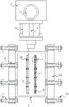
图1为本实用新型的正视剖面结构示意图;Fig. 1 is the front view sectional structure schematic diagram of the utility model;
图2为本实用新型的侧视剖面结构示意图;Fig. 2 is a side view sectional structure schematic diagram of the utility model;
图3为本实用新型的图2中A处局部剖面放大结构示意图;Fig. 3 is a schematic diagram of a partial section enlarged structure at A in Fig. 2 of the present utility model;
图4为本实用新型的固定座正视剖面结构示意图。Fig. 4 is a schematic cross-sectional structure schematic diagram of the front view of the fixing seat of the present invention.
图中:1、阀座;2、阀板;3、连接杆;4、密封圈;5、预留孔;6、安装座;7、驱动杆;8、固定座;9、大齿轮;10、小齿轮;11、驱动电机;12、安装板;13、连接螺栓;14、拆装螺栓;15、定位螺母;16、耐高温橡胶垫。In the figure: 1. Valve seat; 2. Valve plate; 3. Connecting rod; 4. Sealing ring; 5. Reserved hole; 6. Mounting seat; 7. Driving rod; 8. Fixed seat; 9. Big gear; 10 , pinion gear; 11, driving motor; 12, mounting plate; 13, connecting bolts; 14, disassembly bolts; 15, positioning nuts; 16, high temperature resistant rubber pads.
具体实施方式Detailed ways
下面将结合本实用新型实施例中的附图,对本实用新型实施例中的技术方案进行清楚、完整地描述,显然,所描述的实施例仅仅是本实用新型一部分实施例,而不是全部的实施例。基于本实用新型中的实施例,本领域普通技术人员在没有做出创造性劳动前提下所获得的所有其他实施例,都属于本实用新型保护的范围。The technical solutions in the embodiments of the present invention will be clearly and completely described below in conjunction with the accompanying drawings in the embodiments of the present invention. Obviously, the described embodiments are only part of the embodiments of the present invention, not all of them. example. Based on the embodiments of the present utility model, all other embodiments obtained by persons of ordinary skill in the art without making creative efforts belong to the scope of protection of the present utility model.
实施例1:请参阅图1-4,耐高温高密封蝶阀,包括阀座1,阀座1的内部设置有阀板2,阀板2的内部竖向连接有连接杆3,阀座1的顶部安装有安装座6,安装座6的顶部安装有固定座8,阀板2的外圈安装有密封圈4,阀板2的两端设置有耐高温橡胶垫16,耐高温橡胶垫16的周围装配有拆装螺栓14,拆装螺栓14的一侧贯穿于阀板2的内部,耐高温橡胶垫16覆盖在阀板2的表面;Embodiment 1: Please refer to Figures 1-4, a high temperature resistant high sealing butterfly valve, including a valve seat 1, a
具体地,如图1、图2和图3所示,阀板2的外侧安装有密封圈4,密封效果好,不易发生泄漏,阀板2的两端设置有耐高温橡胶垫16,耐高温橡胶垫16耐高温性能优异,高温流体先与耐高温橡胶垫16接触,不会直接与阀板2接触,从而减少高温对阀板2造成的损坏,实现了耐高温高密封的目的。Specifically, as shown in Figure 1, Figure 2 and Figure 3, a sealing ring 4 is installed on the outside of the
实施例2:连接杆3的顶部贯穿于安装座6的内部并与驱动杆7连接,固定座8内部的底端装配有大齿轮9,大齿轮9内部的右侧装配有小齿轮10,固定座8的右侧安装有驱动电机11,驱动电机11的输出端与小齿轮10连接,小齿轮10垂直于大齿轮9的上方,驱动杆7的顶部与大齿轮9连接;Embodiment 2: The top of the connecting
具体地,如图1和图4所示,启动驱动电机11,在驱动电机11的驱动下,带动小齿轮10开始旋转,从而带动大齿轮9和驱动杆7旋转运行,驱动杆7底部与连接杆3连接,从而带动阀板2沿连接杆3的轴线转动,当阀板2平面与管子轴线一致时,为全开,阀板2平面与管子轴线垂直时,为全闭,自动化效率较高,提高了调节的效率。Specifically, as shown in Figures 1 and 4, start the
实施例3:阀座1的两端固定连接有安装板12,安装板12的周围开设有预留孔5,预留孔5的内部贯穿有连接螺栓13,连接螺栓13的外部套接有定位螺母15,定位螺母15的内侧壁上设置有内螺纹,连接螺栓13和定位螺母15之间为螺纹连接;Embodiment 3: The two ends of the valve seat 1 are fixedly connected with a
具体地,如图1和图2所示,将阀座1放在管道之间,使阀座1的左侧与一组管道的连接板贴合,阀座1的右侧与另一组管道的连接板贴合,之后利用安装工具,将连接螺栓13穿过安装板12的内部并贯穿于连接板的安装孔,再将定位螺母15套在连接螺栓13的尾部,将定位螺母15旋转拧紧,实现对阀座1的安装固定,操作难度低。Specifically, as shown in Figure 1 and Figure 2, the valve seat 1 is placed between the pipes, so that the left side of the valve seat 1 fits the connecting plate of one group of pipes, and the right side of the valve seat 1 fits the connecting plate of another group of pipes. Then use the installation tool to pass the connecting bolt 13 through the inside of the
工作原理:本实用新型在使用时,首先,先将阀座1与管道连接时,将阀座1放在管道之间,使阀座1的左侧与一组管道的连接板贴合,阀座1的右侧与另一组管道的连接板贴合,之后利用安装工具,将连接螺栓13穿过安装板12的内部并贯穿于连接板的安装孔,再将定位螺母15套在连接螺栓13的尾部,将定位螺母15旋转拧紧,实现对阀座1的安装固定,阀板2的外侧安装有密封圈4,密封效果好,不易发生泄漏,阀板2的两端设置有耐高温橡胶垫16,耐高温橡胶垫16耐高温性能优异,高温流体先与耐高温橡胶垫16接触,不会直接与阀板2接触,从而减少高温对阀板2造成的损坏,对流体调节时,启动驱动电机11,在驱动电机11的驱动下,带动小齿轮10开始旋转,小齿轮10和大齿轮9之间为啮合连接,从而带动大齿轮9和驱动杆7旋转运行,驱动杆7底部与连接杆3连接,从而带动阀板2沿连接杆3的轴线转动,当阀板2平面与管子轴线一致时,为全开,阀板2平面与管子轴线垂直时,为全闭,实现对流体的调节控制。Working principle: When the utility model is in use, firstly, when connecting the valve seat 1 with the pipeline, place the valve seat 1 between the pipelines so that the left side of the valve seat 1 fits the connecting plate of a group of pipelines, and the valve The right side of the seat 1 is attached to the connecting plate of another group of pipes, and then using the installation tool, the connecting bolt 13 is passed through the inside of the
对于本领域技术人员而言,显然本实用新型不限于上述示范性实施例的细节,而且在不背离本实用新型的精神或基本特征的情况下,能够以其他的具体形式实现本实用新型。因此,无论从哪一点来看,均应将实施例看作是示范性的,而且是非限制性的,本实用新型的范围由所附权利要求而不是上述说明限定,因此旨在将落在权利要求的等同要件的含义和范围内的所有变化囊括在本实用新型内。不应将权利要求中的任何附图标记视为限制所涉及的权利要求。It is obvious to those skilled in the art that the present invention is not limited to the details of the above exemplary embodiments, and that the present invention can be implemented in other specific forms without departing from the spirit or essential features of the present invention. Therefore, no matter from all points of view, the embodiments should be regarded as exemplary and non-restrictive, and the scope of the present invention is defined by the appended claims rather than the above description, so it is intended to fall within the scope of the claims All changes within the meaning and range of equivalents of the required elements are included in the present invention. Any reference sign in a claim should not be construed as limiting the claim concerned.
Claims (6)
Priority Applications (1)
| Application Number | Priority Date | Filing Date | Title |
|---|---|---|---|
| CN202221988985.XU CN217927189U (en) | 2022-07-30 | 2022-07-30 | High-temperature-resistant high-sealing butterfly valve |
Applications Claiming Priority (1)
| Application Number | Priority Date | Filing Date | Title |
|---|---|---|---|
| CN202221988985.XU CN217927189U (en) | 2022-07-30 | 2022-07-30 | High-temperature-resistant high-sealing butterfly valve |
Publications (1)
| Publication Number | Publication Date |
|---|---|
| CN217927189U true CN217927189U (en) | 2022-11-29 |
Family
ID=84151086
Family Applications (1)
| Application Number | Title | Priority Date | Filing Date |
|---|---|---|---|
| CN202221988985.XU Active CN217927189U (en) | 2022-07-30 | 2022-07-30 | High-temperature-resistant high-sealing butterfly valve |
Country Status (1)
| Country | Link |
|---|---|
| CN (1) | CN217927189U (en) |
-
2022
- 2022-07-30 CN CN202221988985.XU patent/CN217927189U/en active Active
Similar Documents
| Publication | Publication Date | Title |
|---|---|---|
| CN204227012U (en) | A kind of top dress interlock three-way switch valve | |
| CN222296984U (en) | Leakage-proof electric butterfly valve | |
| CN212004507U (en) | a float valve | |
| CN213298848U (en) | Silt-proof butterfly valve | |
| CN217874477U (en) | An online monitoring device for the leakage state of a stop valve | |
| CN212055885U (en) | Soft sealing eccentric butterfly valve | |
| CN216519861U (en) | Electric valve for oil exploitation conveying pipeline | |
| CN223344698U (en) | Lug butterfly valve | |
| CN223895145U (en) | Vertical check valve | |
| CN220850775U (en) | An electric regulating valve | |
| CN218094257U (en) | Shut-off valve | |
| CN222085161U (en) | A butterfly valve for long-distance heating pipeline | |
| CN223270650U (en) | A valve that is easy to disassemble and install | |
| CN212203151U (en) | A flanged butterfly valve with handwheel | |
| CN222334520U (en) | Butterfly valve convenient to overhaul | |
| CN221547861U (en) | A check valve that is easy to disassemble and assemble | |
| CN221857542U (en) | Stop valve of milking equipment | |
| CN207715764U (en) | A maintenance-free butterfly valve with reliable sealing | |
| CN222746616U (en) | Butterfly valve driving valve | |
| CN218408563U (en) | Sanitary butterfly valve | |
| CN220646795U (en) | Multilayer sealing butterfly valve convenient to equipment | |
| CN223923946U (en) | Blind valve | |
| CN221943206U (en) | Fluorine-lined stop valve | |
| CN221922120U (en) | A quick-release check valve | |
| CN219639502U (en) | Self-help supplementary seal seat vacuum ball valve |
Legal Events
| Date | Code | Title | Description |
|---|---|---|---|
| GR01 | Patent grant | ||
| GR01 | Patent grant |